EP0340946A2 - Heat insulating ceramic articles for use in exhaust channels in internal combustion engines and a process for producing the same - Google Patents
Heat insulating ceramic articles for use in exhaust channels in internal combustion engines and a process for producing the same Download PDFInfo
- Publication number
- EP0340946A2 EP0340946A2 EP89303988A EP89303988A EP0340946A2 EP 0340946 A2 EP0340946 A2 EP 0340946A2 EP 89303988 A EP89303988 A EP 89303988A EP 89303988 A EP89303988 A EP 89303988A EP 0340946 A2 EP0340946 A2 EP 0340946A2
- Authority
- EP
- European Patent Office
- Prior art keywords
- heat insulating
- ceramic
- ceramic liner
- layer
- liner
- Prior art date
- Legal status (The legal status is an assumption and is not a legal conclusion. Google has not performed a legal analysis and makes no representation as to the accuracy of the status listed.)
- Granted
Links
Images
Classifications
-
- F—MECHANICAL ENGINEERING; LIGHTING; HEATING; WEAPONS; BLASTING
- F01—MACHINES OR ENGINES IN GENERAL; ENGINE PLANTS IN GENERAL; STEAM ENGINES
- F01N—GAS-FLOW SILENCERS OR EXHAUST APPARATUS FOR MACHINES OR ENGINES IN GENERAL; GAS-FLOW SILENCERS OR EXHAUST APPARATUS FOR INTERNAL COMBUSTION ENGINES
- F01N13/00—Exhaust or silencing apparatus characterised by constructional features ; Exhaust or silencing apparatus, or parts thereof, having pertinent characteristics not provided for in, or of interest apart from, groups F01N1/00 - F01N5/00, F01N9/00, F01N11/00
- F01N13/08—Other arrangements or adaptations of exhaust conduits
- F01N13/10—Other arrangements or adaptations of exhaust conduits of exhaust manifolds
- F01N13/102—Other arrangements or adaptations of exhaust conduits of exhaust manifolds having thermal insulation
-
- F—MECHANICAL ENGINEERING; LIGHTING; HEATING; WEAPONS; BLASTING
- F01—MACHINES OR ENGINES IN GENERAL; ENGINE PLANTS IN GENERAL; STEAM ENGINES
- F01N—GAS-FLOW SILENCERS OR EXHAUST APPARATUS FOR MACHINES OR ENGINES IN GENERAL; GAS-FLOW SILENCERS OR EXHAUST APPARATUS FOR INTERNAL COMBUSTION ENGINES
- F01N13/00—Exhaust or silencing apparatus characterised by constructional features ; Exhaust or silencing apparatus, or parts thereof, having pertinent characteristics not provided for in, or of interest apart from, groups F01N1/00 - F01N5/00, F01N9/00, F01N11/00
- F01N13/14—Exhaust or silencing apparatus characterised by constructional features ; Exhaust or silencing apparatus, or parts thereof, having pertinent characteristics not provided for in, or of interest apart from, groups F01N1/00 - F01N5/00, F01N9/00, F01N11/00 having thermal insulation
- F01N13/141—Double-walled exhaust pipes or housings
-
- F—MECHANICAL ENGINEERING; LIGHTING; HEATING; WEAPONS; BLASTING
- F01—MACHINES OR ENGINES IN GENERAL; ENGINE PLANTS IN GENERAL; STEAM ENGINES
- F01N—GAS-FLOW SILENCERS OR EXHAUST APPARATUS FOR MACHINES OR ENGINES IN GENERAL; GAS-FLOW SILENCERS OR EXHAUST APPARATUS FOR INTERNAL COMBUSTION ENGINES
- F01N13/00—Exhaust or silencing apparatus characterised by constructional features ; Exhaust or silencing apparatus, or parts thereof, having pertinent characteristics not provided for in, or of interest apart from, groups F01N1/00 - F01N5/00, F01N9/00, F01N11/00
- F01N13/16—Selection of particular materials
-
- F—MECHANICAL ENGINEERING; LIGHTING; HEATING; WEAPONS; BLASTING
- F02—COMBUSTION ENGINES; HOT-GAS OR COMBUSTION-PRODUCT ENGINE PLANTS
- F02B—INTERNAL-COMBUSTION PISTON ENGINES; COMBUSTION ENGINES IN GENERAL
- F02B77/00—Component parts, details or accessories, not otherwise provided for
- F02B77/02—Surface coverings of combustion-gas-swept parts
-
- F—MECHANICAL ENGINEERING; LIGHTING; HEATING; WEAPONS; BLASTING
- F02—COMBUSTION ENGINES; HOT-GAS OR COMBUSTION-PRODUCT ENGINE PLANTS
- F02F—CYLINDERS, PISTONS OR CASINGS, FOR COMBUSTION ENGINES; ARRANGEMENTS OF SEALINGS IN COMBUSTION ENGINES
- F02F7/00—Casings, e.g. crankcases or frames
- F02F7/0085—Materials for constructing engines or their parts
- F02F7/0087—Ceramic materials
-
- F—MECHANICAL ENGINEERING; LIGHTING; HEATING; WEAPONS; BLASTING
- F02—COMBUSTION ENGINES; HOT-GAS OR COMBUSTION-PRODUCT ENGINE PLANTS
- F02B—INTERNAL-COMBUSTION PISTON ENGINES; COMBUSTION ENGINES IN GENERAL
- F02B1/00—Engines characterised by fuel-air mixture compression
- F02B1/02—Engines characterised by fuel-air mixture compression with positive ignition
- F02B1/04—Engines characterised by fuel-air mixture compression with positive ignition with fuel-air mixture admission into cylinder
-
- F—MECHANICAL ENGINEERING; LIGHTING; HEATING; WEAPONS; BLASTING
- F05—INDEXING SCHEMES RELATING TO ENGINES OR PUMPS IN VARIOUS SUBCLASSES OF CLASSES F01-F04
- F05C—INDEXING SCHEME RELATING TO MATERIALS, MATERIAL PROPERTIES OR MATERIAL CHARACTERISTICS FOR MACHINES, ENGINES OR PUMPS OTHER THAN NON-POSITIVE-DISPLACEMENT MACHINES OR ENGINES
- F05C2203/00—Non-metallic inorganic materials
- F05C2203/08—Ceramics; Oxides
-
- F—MECHANICAL ENGINEERING; LIGHTING; HEATING; WEAPONS; BLASTING
- F05—INDEXING SCHEMES RELATING TO ENGINES OR PUMPS IN VARIOUS SUBCLASSES OF CLASSES F01-F04
- F05C—INDEXING SCHEME RELATING TO MATERIALS, MATERIAL PROPERTIES OR MATERIAL CHARACTERISTICS FOR MACHINES, ENGINES OR PUMPS OTHER THAN NON-POSITIVE-DISPLACEMENT MACHINES OR ENGINES
- F05C2253/00—Other material characteristics; Treatment of material
- F05C2253/16—Fibres
Definitions
- the present invention relates to heat insulating ceramic articles for use in exhaust passages in internal combustion engines and a process for producing the same.
- Another object of the present invention is to provide a process for producing such a heat insulating ceramic article.
- the present invention provides a heat insulating ceramic insert-cast article for the internal combustion engine exhaust passage, characterized in that a boundary face between a ceramic port liner to be brought into contact with exhaust gases and a metallic member enclosing the outer periphery of the ceramic liner is constituted by portions at which the ceramic liner and the metallic member partially contact each other and heat insulating air layers.
- Such a heat insulating ceramic insert-cast article may be produced by covering the outer peripheral surface of the ceramic port liner with a heat insulating layer in which cuts are partially formed, and enclosing the ceramic port liner with a metal as it is so that the metal flows and solidifies in the cuts to form contacting surfaces and that portions into which the molten metal is prevented from flowing by the heat insulating layers are formed as the heat insulating air layers.
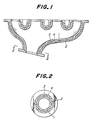
- Fig. 1 is sectionally shown an exhaust manifold as an embodiment to which the present invention is applied.
- Reference numerals 1 and 2 are a ceramic liner for an exhaust manifold and a metallic member, respectively.
- the metallic member is made of such as an aluminum alloy, and encloses the outer periphery of the ceramic liner.
- the ceramic liner 1 is made of a ceramic material, for instance, containing not less than 65% of aluminum titanate as a crystalline phase, and having the average particle size of not less than 10 ⁇ m, a Young's modulus of 50 to 2,000 kgf/mm2, a compression strength of 5 to 40 kgf/mm2, a porosity of 5 to 35%, and a heat conductivity of about 0.8 to 50x103 cal ⁇ cm ⁇ sec ⁇ °c.
- a ceramic material for instance, containing not less than 65% of aluminum titanate as a crystalline phase, and having the average particle size of not less than 10 ⁇ m, a Young's modulus of 50 to 2,000 kgf/mm2, a compression strength of 5 to 40 kgf/mm2, a porosity of 5 to 35%, and a heat conductivity of about 0.8 to 50x103 cal ⁇ cm ⁇ sec ⁇ °c.
- a joint boundary between the ceramic port liner 1 and a metallic member 2 is constituted by contact faces 3 at which the ceramic liner 1 directly contacts with the metallic member and heat insulating air layers 4 at which they do not contact together.
- the contact faces 3 may be designed in the liner, spiral, or dotted fashion. It is preferable that the contact faces 3 are uniformly distributed over the entire joining boundary face between the ceramic liner 1 and the metallic member 2. However this is not an essential restriction, and e.g. slight deviation therefrom is acceptable.
- the contact faces 3 serve to hold the ceramic liner, and it is preferable to decrease the contact faces 3 and to increase the area of the heat insulating air layers 4 so that the heat insulation may be improved.
- the total area of the contact faces is not more than 35% of the entire area of the boundary face, and preferably not more than 10%.
- the thickness of the heat insulating air layer is preferably 0.5 to 5 mm.
- the interior of the heat insulating air layer is void, or may be filled with fibers or the like.
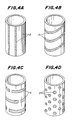
- Fig. 3 shows an embodiment in which the present invention is applied to a port liner.
- the structure of a joining boundary is the same as the above exhaust manifold.
- the ceramic liner 1 itself not only has heat insulating property and but also the heat insulating air layers 4 exhibit excellent heat insulating effect, the temperature of exhaust gases can be maintained high by such a heat insulating ceramic insert-cast article according to the present invention. Furthermore, since the outer periphery of the ceramic liner 1 is directly supported by the contact faces 3 partially formed at the joint boundary with accuracy according to the present invention, it is not feared that the forces for holding the ceramic liner 1 are lowered.
- the outer periphery of the ceramic liner 1 is covered with a layer which can withstand a molten metal during enclosing. It is preferable to use a water-soluble glass powder or a water-soluble glass fiber sheet which can be removed after the enclosing, or a cast sand solidified by a cold box process.
- the glass fiber sheet is made of glass containing not less than 30% by weight of boron oxide, and preferably not less than 50% by weight. This glass fiber sheet can sufficiently withstand the temperature at which the ceramic liner is enclosed with aluminum, which is terminated in short time, and can readily be dissolved off with hot water containing an alkaline compound such as NaOH.
- the cold box process is a process in which an isocyanate resin is added to cast sand as a binder, and is cured with an amine gas after shaping. After the heat treatment at around 500°C, the resin can easily be broken by light vibrations. Such a layer is partially formed with cuts.
- the ceramic liner 1 is enclosed with the molten metal in the sate that the liner is covered with this layer, the molten metal flows into the cuts formed in the layer, and solidifies there to form contact faces between the ceramic liner 1 and the metallic member 2.
- portions at which the molten metal is prevented by the layer from flowing inside are converted to the heat insulating air layers as voids by removing the layer with hot water or by heat treatment.
- the material of the layer besides the above materials, a general fiber sheet may be used. In this case, the sheet may mechanically be scraped out after the solidification. When the porosity of the layer itself is large, the layer may be retained as a heat insulating layer 4 without being removed.
- the heat insulating ceramic insert-cast article according to the present invention may easily and inexpensively be produced by the above process.
- a cylinder having an outer diameter of 30 mm, a thickness of 4 mm, and a length of 300 mm was prepared from a ceramic material containing aluminum titanate as main crystals and having a Young's modulus of 200 kgf/mm2.
- a water-soluble glass fiber sheet was fitted around the outer periphery of the cylinder, which was enclosed with aluminum.
- the sheet was formed with a number of 3 mm diameter holes to give an area ratio of the contact faces of 10% or 20%.
- an insert-cast product having an outer diameter of 45 mm and a length of 300 mm was obtained. After cooling, the water-soluble glass fiber sheet was removed by washing with water.
- the present invention has various merits. That is, heat insulating effect is excellent, and the temperature of exhaust gases can be maintained sufficiently higher as compared with conventional articles. Further, it is not feared that the force for holding the ceramic liner will lower, the structure is simple, and production can inexpensively be done.
- the ceramic insert-cast article according to the present invention is preferable for the cylinder head exhaust port or the exhaust manifold. Thus, the present invention can solve the conventional problems.
Landscapes
- Engineering & Computer Science (AREA)
- Chemical & Material Sciences (AREA)
- Combustion & Propulsion (AREA)
- Mechanical Engineering (AREA)
- General Engineering & Computer Science (AREA)
- Ceramic Engineering (AREA)
- Exhaust Silencers (AREA)
- Cylinder Crankcases Of Internal Combustion Engines (AREA)
- Pistons, Piston Rings, And Cylinders (AREA)
- Ceramic Products (AREA)
Abstract
Description
- The present invention relates to heat insulating ceramic articles for use in exhaust passages in internal combustion engines and a process for producing the same.
- In a system for purifying exhaust gases from internal combustion engines such as gasoline engines and diesel engines and for preventing air pollution with such exhaust gases, it is desired that the temperature of the exhaust gases is maintained high, because reduction in the temperature of the exhaust gases lowers the purifying performance of the catalyst. For this reason, as described in Japanese patent publication No. 51-16,168, it is proposed that an exhaust port in a cylinder head or an exhaust manifold is lined with a heat insulating ceramic liner. Although such a ceramic liner is enclosed with a metal such as aluminum or the like, its heat insulating effect is not sufficient because the thickness of the liner is about 2 to 3 mm. As a result, the temperature of exhaust gases merely increases by about 20°C as compared with a case where no liner is provided.
- Under the circumstances, a trial is made, in which fibers made of a refractory material are wound around the outer periphery of a ceramic liner, and then the ceramic liner is enclosed so that heat insulation is enhanced by the fiber layer. However, since the fibers are gradually damaged due to thermal shocks on starting and stopping of engines or due to engine vibrations and heat, they lose ability to hold the ceramic liner. Ultimately, there is the possibility that the ceramic liner slips out from the fibers. Furthermore, as shown in Japanese Utility Model Registration Application Laid-open No. 54-56,010, a space is formed by arranging a metallic plate around the outer periphery of a ceramic liner so that heat insulating property possessed by air may be utilized. However, since the structure is complicated and the production cost is great and since the ceramic liner is held at opposite ends only, there is a problem in that forces for holding the ceramic liner are likely to be lost.
- It is an object of the present invention to solve the above-mentioned conventional problems, and to provide a heat insulating ceramic article for an exhaust passage in an internal combustion engine, which article can keep the temperature of exhaust gases sufficiently higher than in conventional articles, is free from reduction in forces for holding a ceramic liner, is not structurally complicated, and can inexpensively be manufactured.
- Another object of the present invention is to provide a process for producing such a heat insulating ceramic article.
- The present invention provides a heat insulating ceramic insert-cast article for the internal combustion engine exhaust passage, characterized in that a boundary face between a ceramic port liner to be brought into contact with exhaust gases and a metallic member enclosing the outer periphery of the ceramic liner is constituted by portions at which the ceramic liner and the metallic member partially contact each other and heat insulating air layers.
- Such a heat insulating ceramic insert-cast article may be produced by covering the outer peripheral surface of the ceramic port liner with a heat insulating layer in which cuts are partially formed, and enclosing the ceramic port liner with a metal as it is so that the metal flows and solidifies in the cuts to form contacting surfaces and that portions into which the molten metal is prevented from flowing by the heat insulating layers are formed as the heat insulating air layers.
- These and other optional features and advantages of the invention will be appreciated upon reading of the following description of the invention when taken in conjunction with the attached drawings, with the understanding that some modifications, variations and changes of the same could be made by the skilled person in the art to which the invention pertains.
- For a better understanding of the invention, reference is made to the attached drawings, wherein:
- Fig. 1 is a sectional view of an exhaust manifold as a first embodiment according to the present invention;
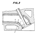
- Fig. 2 is a sectional view of Fig. 1 taken along a line II-II;
- Fig. 3 is a sectional view of a cylinder head exhaust port liner as a second embodiment according to the present invention; and
- Fig. 4(A) through Fig. 4(D) are perspective views of diagrammatically illustrating joining boundaries between ceramic liners and metallic members.
- The present invention will be explained in more detail with reference to the attached drawings:
- In Fig. 1 is sectionally shown an exhaust manifold as an embodiment to which the present invention is applied.
Reference numerals 1 and 2 are a ceramic liner for an exhaust manifold and a metallic member, respectively. The metallic member is made of such as an aluminum alloy, and encloses the outer periphery of the ceramic liner. The ceramic liner 1 is made of a ceramic material, for instance, containing not less than 65% of aluminum titanate as a crystalline phase, and having the average particle size of not less than 10 µm, a Young's modulus of 50 to 2,000 kgf/mm², a compression strength of 5 to 40 kgf/mm², a porosity of 5 to 35%, and a heat conductivity of about 0.8 to 50x10³ cal·cm·sec·°c. Thereby, the ceramic liner 1 can be prevented from being cracked during casting even in a complicated shape such as a bifurcated port liner. As shown in Fig. 1, a joint boundary between the ceramic port liner 1 and ametallic member 2 is constituted bycontact faces 3 at which the ceramic liner 1 directly contacts with the metallic member and heat insulatingair layers 4 at which they do not contact together. As diagrammatically shown in Fig. 4(A) through Fig. 4(D), thecontact faces 3 may be designed in the liner, spiral, or dotted fashion. It is preferable that thecontact faces 3 are uniformly distributed over the entire joining boundary face between the ceramic liner 1 and themetallic member 2. However this is not an essential restriction, and e.g. slight deviation therefrom is acceptable. Thecontact faces 3 serve to hold the ceramic liner, and it is preferable to decrease thecontact faces 3 and to increase the area of the heat insulatingair layers 4 so that the heat insulation may be improved. Practically, the total area of the contact faces is not more than 35% of the entire area of the boundary face, and preferably not more than 10%. The thickness of the heat insulating air layer is preferably 0.5 to 5 mm. The interior of the heat insulating air layer is void, or may be filled with fibers or the like. - Fig. 3 shows an embodiment in which the present invention is applied to a port liner. The structure of a joining boundary is the same as the above exhaust manifold.
- Since the ceramic liner 1 itself not only has heat insulating property and but also the heat insulating
air layers 4 exhibit excellent heat insulating effect, the temperature of exhaust gases can be maintained high by such a heat insulating ceramic insert-cast article according to the present invention. Furthermore, since the outer periphery of the ceramic liner 1 is directly supported by thecontact faces 3 partially formed at the joint boundary with accuracy according to the present invention, it is not feared that the forces for holding the ceramic liner 1 are lowered. - Next, the process for producing heat insulating ceramic insert-cast article according to the present invention will be explained.
- First, the outer periphery of the ceramic liner 1 is covered with a layer which can withstand a molten metal during enclosing. It is preferable to use a water-soluble glass powder or a water-soluble glass fiber sheet which can be removed after the enclosing, or a cast sand solidified by a cold box process. The glass fiber sheet is made of glass containing not less than 30% by weight of boron oxide, and preferably not less than 50% by weight. This glass fiber sheet can sufficiently withstand the temperature at which the ceramic liner is enclosed with aluminum, which is terminated in short time, and can readily be dissolved off with hot water containing an alkaline compound such as NaOH. On the other hand, the cold box process is a process in which an isocyanate resin is added to cast sand as a binder, and is cured with an amine gas after shaping. After the heat treatment at around 500°C, the resin can easily be broken by light vibrations. Such a layer is partially formed with cuts. When the ceramic liner 1 is enclosed with the molten metal in the sate that the liner is covered with this layer, the molten metal flows into the cuts formed in the layer, and solidifies there to form contact faces between the ceramic liner 1 and the
metallic member 2. On the other hand, portions at which the molten metal is prevented by the layer from flowing inside are converted to the heat insulating air layers as voids by removing the layer with hot water or by heat treatment. As the material of the layer, besides the above materials, a general fiber sheet may be used. In this case, the sheet may mechanically be scraped out after the solidification. When the porosity of the layer itself is large, the layer may be retained as aheat insulating layer 4 without being removed. The heat insulating ceramic insert-cast article according to the present invention may easily and inexpensively be produced by the above process. - In order to confirm the effect of the articles according to the present invention, the following experiment was conducted.
- A cylinder having an outer diameter of 30 mm, a thickness of 4 mm, and a length of 300 mm was prepared from a ceramic material containing aluminum titanate as main crystals and having a Young's modulus of 200 kgf/mm². Next, a water-soluble glass fiber sheet was fitted around the outer periphery of the cylinder, which was enclosed with aluminum. The sheet was formed with a number of 3 mm diameter holes to give an area ratio of the contact faces of 10% or 20%. As a result, an insert-cast product having an outer diameter of 45 mm and a length of 300 mm was obtained. After cooling, the water-soluble glass fiber sheet was removed by washing with water.
- Exhaust gases from an engine at 700°C were led to each of the thus obtained test pieces, and heat insulating effect thereof was evaluated. As compared with an exhaust pipe made of a stainless steel with no ceramic cylinder, the temperature of the exhaust gases could be maintained higher by 70°C and 60°C in the case of the aluminum insert-cast test pieces having the area ratio of the contact faces 3 being 10% and 20%, respectively. Furthermore, in the case of a test piece in which a ceramic fiber sheet having a larger porosity and holes formed therein to give an area ratio of the
contact faces 3 being 20% was used and not removed after insert-casting, the temperature of the exhaust gases could be maintained higher by about 40°C. The temperature of the exhaust gases could be maintained higher by about 20°C in the case of a ceramic liner directly enclosed with aluminum in which the area ratio of thecontact face 3 was 100%. - As is clear from the foregoing explanation, the present invention has various merits. That is, heat insulating effect is excellent, and the temperature of exhaust gases can be maintained sufficiently higher as compared with conventional articles. Further, it is not feared that the force for holding the ceramic liner will lower, the structure is simple, and production can inexpensively be done. Thus, the ceramic insert-cast article according to the present invention is preferable for the cylinder head exhaust port or the exhaust manifold. Thus, the present invention can solve the conventional problems.
Claims (8)
Applications Claiming Priority (2)
| Application Number | Priority Date | Filing Date | Title |
|---|---|---|---|
| JP63109754A JPH01280616A (en) | 1988-05-02 | 1988-05-02 | Enveloping cast of heat insulating ceramic for exhaust channel of internal combustion engine and its manufacture |
| JP109754/88 | 1988-05-02 |
Publications (3)
| Publication Number | Publication Date |
|---|---|
| EP0340946A2 true EP0340946A2 (en) | 1989-11-08 |
| EP0340946A3 EP0340946A3 (en) | 1990-01-31 |
| EP0340946B1 EP0340946B1 (en) | 1993-03-17 |
Family
ID=14518402
Family Applications (1)
| Application Number | Title | Priority Date | Filing Date |
|---|---|---|---|
| EP89303988A Expired - Lifetime EP0340946B1 (en) | 1988-05-02 | 1989-04-21 | Heat insulating ceramic articles for use in exhaust channels in internal combustion engines and a process for producing the same |
Country Status (4)
| Country | Link |
|---|---|
| US (1) | US4972674A (en) |
| EP (1) | EP0340946B1 (en) |
| JP (1) | JPH01280616A (en) |
| DE (1) | DE68905367T2 (en) |
Cited By (7)
| Publication number | Priority date | Publication date | Assignee | Title |
|---|---|---|---|---|
| EP1129277A1 (en) * | 1998-10-12 | 2001-09-05 | Nu-Chem, Inc. | Insulative shield, particularly for automotive exhaust components |
| WO2006117454A1 (en) * | 2005-05-04 | 2006-11-09 | Faurecia Systemes D'echappement | Exhaust manifold |
| WO2006117468A1 (en) * | 2005-05-04 | 2006-11-09 | Faurecia Systemes D'echappement | Double-shell manifold |
| FR2899933A1 (en) * | 2006-04-14 | 2007-10-19 | Faurecia Sys Echappement | COMPOSITE EXHAUST MANIFOLD |
| FR2916228A1 (en) * | 2007-05-16 | 2008-11-21 | Faurecia Sys Echappement | Exhaust unit for exhaust manifold of engine, has ducts respectively defining internal walls that are separated by free space, where one of walls of one duct has spacer projection supported against wall of other duct |
| WO2010039590A3 (en) * | 2008-10-01 | 2010-07-01 | Borgwarner Inc. | Exhaust flow insulator for an exhaust system device |
| US9790836B2 (en) | 2012-11-20 | 2017-10-17 | Tenneco Automotive Operating Company, Inc. | Loose-fill insulation exhaust gas treatment device and methods of manufacturing |
Families Citing this family (34)
| Publication number | Priority date | Publication date | Assignee | Title |
|---|---|---|---|---|
| US5142863A (en) * | 1989-05-18 | 1992-09-01 | Honda Giken Kogyo Kabushiki Kaisha | Engine part provided with manifold type exhaust passage |
| US5137789A (en) * | 1990-12-03 | 1992-08-11 | Caterpillar Inc. | Composite ceramic and metal article |
| SE9200871L (en) * | 1991-05-01 | 1992-11-02 | Outboard Marine Corp | PROCEDURE AND DEVICE FOR THE PREPARATION OF SUPPLY DEVICE SHOWING PLACE IN PLACE USING A PRECISION MOLDING PROCESS |
| US5239956A (en) * | 1991-06-07 | 1993-08-31 | Detroit Diesel Corporation | Internal combustion engine cylinder heads and similar articles of manufacture and methods of manufacturing same |
| US5167885A (en) * | 1992-01-07 | 1992-12-01 | W. R. Grace & Co.-Conn. | Method for making sintered bodies |
| JPH05196500A (en) * | 1992-01-22 | 1993-08-06 | Nikko Kyodo Co Ltd | Photometric apparatus |
| JP2589099Y2 (en) * | 1992-04-20 | 1999-01-20 | いすゞ自動車株式会社 | Exhaust manifold mounting structure |
| US5590524A (en) * | 1992-05-14 | 1997-01-07 | Soundwich, Inc. | Damped heat shield |
| JPH07317540A (en) * | 1994-05-27 | 1995-12-05 | Calsonic Corp | Thin walled double-pipe type exhaust manifold |
| US5660399A (en) * | 1995-08-16 | 1997-08-26 | Northrop Grumman Corporation | Piston rings particularly suited for use with ceramic matrix composite pistons and cylinders |
| US5632320A (en) * | 1995-08-16 | 1997-05-27 | Northrop Grumman Corporation | Methods and apparatus for making ceramic matrix composite lined automotive parts and fiber reinforced ceramic matrix composite automotive parts |
| US5879640A (en) * | 1995-08-16 | 1999-03-09 | Northrop Grumman Corporation | Ceramic catalytic converter |
| US5560455A (en) * | 1995-08-16 | 1996-10-01 | Northrop Grumman Corporation | Brakes rotors/drums and brake pads particularly adapted for aircraft/truck/train/ and other heavy duty applications |
| US5687787A (en) * | 1995-08-16 | 1997-11-18 | Northrop Grumman Corporation | Fiber reinforced ceramic matrix composite internal combustion engine exhaust manifold |
| CA2229603A1 (en) * | 1995-08-16 | 1997-02-27 | Edward Strasser | Reducing wear between structural fiber reinforced ceramic matrix composite automotive engine parts in sliding contacting relationship |
| US5582784A (en) * | 1995-08-16 | 1996-12-10 | Northrop Grumman Corporation | Method of making ceramic matrix composite/ceramic foam panels |
| US5740788A (en) * | 1995-08-16 | 1998-04-21 | Northrop Grumman Corporation | Fiber reinforced ceramic matrix composite piston and cylinder/sleeve for an internal combustion engine |
| US5657729A (en) * | 1995-08-16 | 1997-08-19 | Northrop Grumman Corporation | Fiber reinforced ceramic matrix composite cylinder head and cylinder head liner for an internal combustion engine |
| US5643512A (en) * | 1995-08-16 | 1997-07-01 | Northrop Grumman Corporation | Methods for producing ceramic foams using pre-ceramic resins combined with liquid phenolic resin |
| US5692373A (en) * | 1995-08-16 | 1997-12-02 | Northrop Grumman Corporation | Exhaust manifold with integral catalytic converter |
| US5638779A (en) * | 1995-08-16 | 1997-06-17 | Northrop Grumman Corporation | High-efficiency, low-pollution engine |
| US5718046A (en) * | 1995-12-11 | 1998-02-17 | General Motors Corporation | Method of making a ceramic coated exhaust manifold and method |
| US6001436A (en) * | 1997-05-12 | 1999-12-14 | Northrop Grumman Corporation | Ceramic matrix composite turbocharger housing |
| US6265078B1 (en) | 1999-09-09 | 2001-07-24 | Northrop Grumman Corporation | Reducing wear between structural fiber reinforced ceramic matrix composite automotive engine parts in sliding contacting relationship |
| US20040177609A1 (en) * | 2001-12-07 | 2004-09-16 | Moore Dan T. | Insulated exhaust manifold having ceramic inner layer that is highly resistant to thermal cycling |
| US6725656B2 (en) | 2001-12-07 | 2004-04-27 | Dan T. Moore Company | Insulated exhaust manifold |
| US7585559B2 (en) | 2003-06-03 | 2009-09-08 | Intellectual Property Holdings, Llc | Foam barrier heat shield |
| DE102005004651A1 (en) * | 2005-02-02 | 2006-08-10 | Daimlerchrysler Ag | Exhaust gas device of an internal combustion engine with internal lining and method for its production |
| WO2008015583A1 (en) * | 2006-06-13 | 2008-02-07 | Wescast Industries, Inc. | Exhaust manifolds including heat shield assemblies |
| US7799840B2 (en) | 2006-09-12 | 2010-09-21 | Intellectual Property Holdings, Llc | Thermoplastic vibrational damper with constraining layer |
| WO2009086187A2 (en) * | 2007-12-21 | 2009-07-09 | Green Partners Technology Holdings Gmbh | Piston engine systems and methods |
| DE102010048973A1 (en) * | 2010-10-20 | 2012-04-26 | Isolite Gmbh | exhaust manifold |
| JP6866772B2 (en) * | 2017-06-01 | 2021-04-28 | 株式会社豊田自動織機 | How to manufacture the exhaust manifold |
| DE102018121723A1 (en) * | 2018-09-06 | 2020-03-12 | Man Truck & Bus Se | Cylinder head for an internal combustion engine and method for its production |
Citations (4)
| Publication number | Priority date | Publication date | Assignee | Title |
|---|---|---|---|---|
| DE2602434A1 (en) * | 1976-01-23 | 1977-07-28 | Daimler Benz Ag | Sheet metal lining for engine inlet and exhaust ducts - is preformed as two half shells and inserted in mould when casting cylinder head |
| FR2408557A1 (en) * | 1977-11-10 | 1979-06-08 | Rosenthal Technik Ag | REFRACTORY ARTICLE AND METAL-CERAMIC COMPOSITE BODY IN ALUMINUM SILICATE TITANATE |
| US4604779A (en) * | 1984-02-27 | 1986-08-12 | Ngk Spark Plug Co., Ltd. | Method of producing a cylinder head with a port liner |
| EP0212469A2 (en) * | 1985-08-29 | 1987-03-04 | Alcan Deutschland Gmbh | Refractory component and method for producing the same |
Family Cites Families (4)
| Publication number | Priority date | Publication date | Assignee | Title |
|---|---|---|---|---|
| DE1938404A1 (en) * | 1969-07-29 | 1971-02-11 | Daimler Benz Ag | Line and / or space for receiving or guiding hot gases |
| US3892907A (en) * | 1972-11-13 | 1975-07-01 | Toyota Motor Co Ltd | Reinforced refractory heat-insulator |
| JPS5248602B2 (en) * | 1973-03-06 | 1977-12-10 | ||
| JPS55155507A (en) * | 1979-05-22 | 1980-12-03 | Fujikura Ltd | Method of arraying cable |
-
1988
- 1988-05-02 JP JP63109754A patent/JPH01280616A/en active Pending
-
1989
- 1989-04-21 DE DE8989303988T patent/DE68905367T2/en not_active Expired - Fee Related
- 1989-04-21 US US07/341,710 patent/US4972674A/en not_active Expired - Fee Related
- 1989-04-21 EP EP89303988A patent/EP0340946B1/en not_active Expired - Lifetime
Patent Citations (4)
| Publication number | Priority date | Publication date | Assignee | Title |
|---|---|---|---|---|
| DE2602434A1 (en) * | 1976-01-23 | 1977-07-28 | Daimler Benz Ag | Sheet metal lining for engine inlet and exhaust ducts - is preformed as two half shells and inserted in mould when casting cylinder head |
| FR2408557A1 (en) * | 1977-11-10 | 1979-06-08 | Rosenthal Technik Ag | REFRACTORY ARTICLE AND METAL-CERAMIC COMPOSITE BODY IN ALUMINUM SILICATE TITANATE |
| US4604779A (en) * | 1984-02-27 | 1986-08-12 | Ngk Spark Plug Co., Ltd. | Method of producing a cylinder head with a port liner |
| EP0212469A2 (en) * | 1985-08-29 | 1987-03-04 | Alcan Deutschland Gmbh | Refractory component and method for producing the same |
Cited By (15)
| Publication number | Priority date | Publication date | Assignee | Title |
|---|---|---|---|---|
| EP1129277A4 (en) * | 1998-10-12 | 2002-01-23 | Nu Chem Inc | Insulative shield, particularly for automotive exhaust components |
| EP1129277A1 (en) * | 1998-10-12 | 2001-09-05 | Nu-Chem, Inc. | Insulative shield, particularly for automotive exhaust components |
| US8104273B2 (en) | 2005-05-04 | 2012-01-31 | Faurecia Systemes D'echappement | Double-shell manifold |
| WO2006117454A1 (en) * | 2005-05-04 | 2006-11-09 | Faurecia Systemes D'echappement | Exhaust manifold |
| WO2006117468A1 (en) * | 2005-05-04 | 2006-11-09 | Faurecia Systemes D'echappement | Double-shell manifold |
| FR2885385A1 (en) * | 2005-05-04 | 2006-11-10 | Faurecia Sys Echappement | DOUBLE HULL COLLECTOR |
| FR2885386A1 (en) * | 2005-05-04 | 2006-11-10 | Faurecia Sys Echappement | EXHAUST MANIFOLD |
| KR101293122B1 (en) * | 2005-05-04 | 2013-08-12 | 포레시아 씨스뗌 데샤쁘망 | Double-shell manifold |
| FR2899933A1 (en) * | 2006-04-14 | 2007-10-19 | Faurecia Sys Echappement | COMPOSITE EXHAUST MANIFOLD |
| US8245506B2 (en) | 2006-04-14 | 2012-08-21 | Faurecia Systemes D'echappement | Composite exhaust manifold |
| WO2007118969A1 (en) * | 2006-04-14 | 2007-10-25 | Faurecia Systemes D'echappement | Composite exhaust manifold |
| FR2916228A1 (en) * | 2007-05-16 | 2008-11-21 | Faurecia Sys Echappement | Exhaust unit for exhaust manifold of engine, has ducts respectively defining internal walls that are separated by free space, where one of walls of one duct has spacer projection supported against wall of other duct |
| WO2010039590A3 (en) * | 2008-10-01 | 2010-07-01 | Borgwarner Inc. | Exhaust flow insulator for an exhaust system device |
| EP2340364B1 (en) * | 2008-10-01 | 2015-10-21 | Borgwarner Inc. | Exhaust flow insulator for an exhaust system device |
| US9790836B2 (en) | 2012-11-20 | 2017-10-17 | Tenneco Automotive Operating Company, Inc. | Loose-fill insulation exhaust gas treatment device and methods of manufacturing |
Also Published As
| Publication number | Publication date |
|---|---|
| JPH01280616A (en) | 1989-11-10 |
| EP0340946A3 (en) | 1990-01-31 |
| DE68905367D1 (en) | 1993-04-22 |
| DE68905367T2 (en) | 1993-08-12 |
| EP0340946B1 (en) | 1993-03-17 |
| US4972674A (en) | 1990-11-27 |
Similar Documents
| Publication | Publication Date | Title |
|---|---|---|
| EP0340946A2 (en) | Heat insulating ceramic articles for use in exhaust channels in internal combustion engines and a process for producing the same | |
| EP0437303A2 (en) | Ceramic port liners | |
| EP0906496B1 (en) | Free-standing internally insulating liner | |
| US4849266A (en) | Compliant layer | |
| EP0796687B9 (en) | A method for producing a piston for an internal combustion engine and a piston produced by the method | |
| US4676064A (en) | Heat-insulated port liner arrangement and method of fabrication | |
| WO2000075496A1 (en) | High temperature mat for a pollution control device | |
| US20040177609A1 (en) | Insulated exhaust manifold having ceramic inner layer that is highly resistant to thermal cycling | |
| JP3979559B2 (en) | Ceramic honeycomb structure | |
| US5260116A (en) | Ceramicm port liners | |
| US5076054A (en) | Exhaust apparatus for combustion equipment | |
| US4956319A (en) | Compliant layer | |
| Walzer et al. | Ceramic components in passenger-car diesel engines | |
| JPS6014901B2 (en) | Piston manufacturing method | |
| JPS6245964A (en) | Heat insulating piston and manufacture thereof | |
| JPS61142314A (en) | Cast molding manufacture of exhaust gas purifying device | |
| JPH03141850A (en) | Insulated piston and manufacture thereof | |
| JPH05200525A (en) | Production of heat insulating member | |
| JPH074905B2 (en) | Adiabatic ceramic composite and manufacturing method thereof | |
| KR20000016684A (en) | Free-standing internally insulating liner | |
| JPH0313551Y2 (en) | ||
| JP3158456B2 (en) | Adiabatic intake / exhaust port and method of manufacturing the same | |
| JPH0436062B2 (en) | ||
| JP2530760B2 (en) | Ceramic port liner | |
| JPH05213678A (en) | Structure and production of heat-insulating device |
Legal Events
| Date | Code | Title | Description |
|---|---|---|---|
| PUAI | Public reference made under article 153(3) epc to a published international application that has entered the european phase |
Free format text: ORIGINAL CODE: 0009012 |
|
| AK | Designated contracting states |
Kind code of ref document: A2 Designated state(s): BE DE FR GB SE |
|
| PUAL | Search report despatched |
Free format text: ORIGINAL CODE: 0009013 |
|
| AK | Designated contracting states |
Kind code of ref document: A3 Designated state(s): BE DE FR GB SE |
|
| 17P | Request for examination filed |
Effective date: 19900606 |
|
| 17Q | First examination report despatched |
Effective date: 19910417 |
|
| GRAA | (expected) grant |
Free format text: ORIGINAL CODE: 0009210 |
|
| AK | Designated contracting states |
Kind code of ref document: B1 Designated state(s): BE DE |
|
| REF | Corresponds to: |
Ref document number: 68905367 Country of ref document: DE Date of ref document: 19930422 |
|
| EN | Fr: translation not filed | ||
| PLBE | No opposition filed within time limit |
Free format text: ORIGINAL CODE: 0009261 |
|
| STAA | Information on the status of an ep patent application or granted ep patent |
Free format text: STATUS: NO OPPOSITION FILED WITHIN TIME LIMIT |
|
| 26N | No opposition filed | ||
| PGFP | Annual fee paid to national office [announced via postgrant information from national office to epo] |
Ref country code: DE Payment date: 19950419 Year of fee payment: 7 |
|
| PGFP | Annual fee paid to national office [announced via postgrant information from national office to epo] |
Ref country code: BE Payment date: 19950426 Year of fee payment: 7 |
|
| PG25 | Lapsed in a contracting state [announced via postgrant information from national office to epo] |
Ref country code: BE Effective date: 19960430 |
|
| BERE | Be: lapsed |
Owner name: NGK INSULATORS LTD Effective date: 19960430 |
|
| PG25 | Lapsed in a contracting state [announced via postgrant information from national office to epo] |
Ref country code: DE Effective date: 19970101 |