EP0796687B9 - A method for producing a piston for an internal combustion engine and a piston produced by the method - Google Patents
A method for producing a piston for an internal combustion engine and a piston produced by the method Download PDFInfo
- Publication number
- EP0796687B9 EP0796687B9 EP97301176A EP97301176A EP0796687B9 EP 0796687 B9 EP0796687 B9 EP 0796687B9 EP 97301176 A EP97301176 A EP 97301176A EP 97301176 A EP97301176 A EP 97301176A EP 0796687 B9 EP0796687 B9 EP 0796687B9
- Authority
- EP
- European Patent Office
- Prior art keywords
- piston
- insert
- combustion chamber
- combustion
- air chamber
- Prior art date
- Legal status (The legal status is an assumption and is not a legal conclusion. Google has not performed a legal analysis and makes no representation as to the accuracy of the status listed.)
- Expired - Lifetime
Links
Images

Classifications
-
- F—MECHANICAL ENGINEERING; LIGHTING; HEATING; WEAPONS; BLASTING
- F02—COMBUSTION ENGINES; HOT-GAS OR COMBUSTION-PRODUCT ENGINE PLANTS
- F02F—CYLINDERS, PISTONS OR CASINGS, FOR COMBUSTION ENGINES; ARRANGEMENTS OF SEALINGS IN COMBUSTION ENGINES
- F02F3/00—Pistons
- F02F3/0015—Multi-part pistons
- F02F3/003—Multi-part pistons the parts being connected by casting, brazing, welding or clamping
-
- F—MECHANICAL ENGINEERING; LIGHTING; HEATING; WEAPONS; BLASTING
- F02—COMBUSTION ENGINES; HOT-GAS OR COMBUSTION-PRODUCT ENGINE PLANTS
- F02F—CYLINDERS, PISTONS OR CASINGS, FOR COMBUSTION ENGINES; ARRANGEMENTS OF SEALINGS IN COMBUSTION ENGINES
- F02F3/00—Pistons
- F02F3/10—Pistons having surface coverings
- F02F3/12—Pistons having surface coverings on piston heads
- F02F3/14—Pistons having surface coverings on piston heads within combustion chambers
-
- B—PERFORMING OPERATIONS; TRANSPORTING
- B22—CASTING; POWDER METALLURGY
- B22D—CASTING OF METALS; CASTING OF OTHER SUBSTANCES BY THE SAME PROCESSES OR DEVICES
- B22D19/00—Casting in, on, or around objects which form part of the product
- B22D19/0009—Cylinders, pistons
- B22D19/0027—Cylinders, pistons pistons
-
- F—MECHANICAL ENGINEERING; LIGHTING; HEATING; WEAPONS; BLASTING
- F02—COMBUSTION ENGINES; HOT-GAS OR COMBUSTION-PRODUCT ENGINE PLANTS
- F02B—INTERNAL-COMBUSTION PISTON ENGINES; COMBUSTION ENGINES IN GENERAL
- F02B23/00—Other engines characterised by special shape or construction of combustion chambers to improve operation
- F02B23/02—Other engines characterised by special shape or construction of combustion chambers to improve operation with compression ignition
- F02B23/06—Other engines characterised by special shape or construction of combustion chambers to improve operation with compression ignition the combustion space being arranged in working piston
- F02B23/0603—Other engines characterised by special shape or construction of combustion chambers to improve operation with compression ignition the combustion space being arranged in working piston at least part of the interior volume or the wall of the combustion space being made of material different from the surrounding piston part, e.g. combustion space formed within a ceramic part fixed to a metal piston head
- F02B2023/0612—Other engines characterised by special shape or construction of combustion chambers to improve operation with compression ignition the combustion space being arranged in working piston at least part of the interior volume or the wall of the combustion space being made of material different from the surrounding piston part, e.g. combustion space formed within a ceramic part fixed to a metal piston head the material having a high temperature and pressure resistance, e.g. ceramic
-
- F—MECHANICAL ENGINEERING; LIGHTING; HEATING; WEAPONS; BLASTING
- F02—COMBUSTION ENGINES; HOT-GAS OR COMBUSTION-PRODUCT ENGINE PLANTS
- F02B—INTERNAL-COMBUSTION PISTON ENGINES; COMBUSTION ENGINES IN GENERAL
- F02B2275/00—Other engines, components or details, not provided for in other groups of this subclass
- F02B2275/14—Direct injection into combustion chamber
-
- F—MECHANICAL ENGINEERING; LIGHTING; HEATING; WEAPONS; BLASTING
- F02—COMBUSTION ENGINES; HOT-GAS OR COMBUSTION-PRODUCT ENGINE PLANTS
- F02B—INTERNAL-COMBUSTION PISTON ENGINES; COMBUSTION ENGINES IN GENERAL
- F02B23/00—Other engines characterised by special shape or construction of combustion chambers to improve operation
- F02B23/02—Other engines characterised by special shape or construction of combustion chambers to improve operation with compression ignition
- F02B23/06—Other engines characterised by special shape or construction of combustion chambers to improve operation with compression ignition the combustion space being arranged in working piston
- F02B23/0603—Other engines characterised by special shape or construction of combustion chambers to improve operation with compression ignition the combustion space being arranged in working piston at least part of the interior volume or the wall of the combustion space being made of material different from the surrounding piston part, e.g. combustion space formed within a ceramic part fixed to a metal piston head
-
- F—MECHANICAL ENGINEERING; LIGHTING; HEATING; WEAPONS; BLASTING
- F02—COMBUSTION ENGINES; HOT-GAS OR COMBUSTION-PRODUCT ENGINE PLANTS
- F02B—INTERNAL-COMBUSTION PISTON ENGINES; COMBUSTION ENGINES IN GENERAL
- F02B23/00—Other engines characterised by special shape or construction of combustion chambers to improve operation
- F02B23/02—Other engines characterised by special shape or construction of combustion chambers to improve operation with compression ignition
- F02B23/06—Other engines characterised by special shape or construction of combustion chambers to improve operation with compression ignition the combustion space being arranged in working piston
- F02B23/0618—Other engines characterised by special shape or construction of combustion chambers to improve operation with compression ignition the combustion space being arranged in working piston having in-cylinder means to influence the charge motion
- F02B23/0627—Other engines characterised by special shape or construction of combustion chambers to improve operation with compression ignition the combustion space being arranged in working piston having in-cylinder means to influence the charge motion having additional bores or grooves machined into the piston for guiding air or charge flow to the piston bowl
-
- F—MECHANICAL ENGINEERING; LIGHTING; HEATING; WEAPONS; BLASTING
- F02—COMBUSTION ENGINES; HOT-GAS OR COMBUSTION-PRODUCT ENGINE PLANTS
- F02B—INTERNAL-COMBUSTION PISTON ENGINES; COMBUSTION ENGINES IN GENERAL
- F02B23/00—Other engines characterised by special shape or construction of combustion chambers to improve operation
- F02B23/02—Other engines characterised by special shape or construction of combustion chambers to improve operation with compression ignition
- F02B23/06—Other engines characterised by special shape or construction of combustion chambers to improve operation with compression ignition the combustion space being arranged in working piston
- F02B23/0672—Omega-piston bowl, i.e. the combustion space having a central projection pointing towards the cylinder head and the surrounding wall being inclined towards the cylinder center axis
-
- F—MECHANICAL ENGINEERING; LIGHTING; HEATING; WEAPONS; BLASTING
- F02—COMBUSTION ENGINES; HOT-GAS OR COMBUSTION-PRODUCT ENGINE PLANTS
- F02B—INTERNAL-COMBUSTION PISTON ENGINES; COMBUSTION ENGINES IN GENERAL
- F02B3/00—Engines characterised by air compression and subsequent fuel addition
- F02B3/06—Engines characterised by air compression and subsequent fuel addition with compression ignition
-
- F—MECHANICAL ENGINEERING; LIGHTING; HEATING; WEAPONS; BLASTING
- F02—COMBUSTION ENGINES; HOT-GAS OR COMBUSTION-PRODUCT ENGINE PLANTS
- F02F—CYLINDERS, PISTONS OR CASINGS, FOR COMBUSTION ENGINES; ARRANGEMENTS OF SEALINGS IN COMBUSTION ENGINES
- F02F3/00—Pistons
- F02F3/0015—Multi-part pistons
- F02F3/003—Multi-part pistons the parts being connected by casting, brazing, welding or clamping
- F02F2003/0061—Multi-part pistons the parts being connected by casting, brazing, welding or clamping by welding
-
- F—MECHANICAL ENGINEERING; LIGHTING; HEATING; WEAPONS; BLASTING
- F02—COMBUSTION ENGINES; HOT-GAS OR COMBUSTION-PRODUCT ENGINE PLANTS
- F02F—CYLINDERS, PISTONS OR CASINGS, FOR COMBUSTION ENGINES; ARRANGEMENTS OF SEALINGS IN COMBUSTION ENGINES
- F02F2200/00—Manufacturing
- F02F2200/06—Casting
-
- F—MECHANICAL ENGINEERING; LIGHTING; HEATING; WEAPONS; BLASTING
- F05—INDEXING SCHEMES RELATING TO ENGINES OR PUMPS IN VARIOUS SUBCLASSES OF CLASSES F01-F04
- F05C—INDEXING SCHEME RELATING TO MATERIALS, MATERIAL PROPERTIES OR MATERIAL CHARACTERISTICS FOR MACHINES, ENGINES OR PUMPS OTHER THAN NON-POSITIVE-DISPLACEMENT MACHINES OR ENGINES
- F05C2201/00—Metals
- F05C2201/02—Light metals
- F05C2201/021—Aluminium
-
- F—MECHANICAL ENGINEERING; LIGHTING; HEATING; WEAPONS; BLASTING
- F05—INDEXING SCHEMES RELATING TO ENGINES OR PUMPS IN VARIOUS SUBCLASSES OF CLASSES F01-F04
- F05C—INDEXING SCHEME RELATING TO MATERIALS, MATERIAL PROPERTIES OR MATERIAL CHARACTERISTICS FOR MACHINES, ENGINES OR PUMPS OTHER THAN NON-POSITIVE-DISPLACEMENT MACHINES OR ENGINES
- F05C2251/00—Material properties
- F05C2251/04—Thermal properties
- F05C2251/042—Expansivity
-
- Y—GENERAL TAGGING OF NEW TECHNOLOGICAL DEVELOPMENTS; GENERAL TAGGING OF CROSS-SECTIONAL TECHNOLOGIES SPANNING OVER SEVERAL SECTIONS OF THE IPC; TECHNICAL SUBJECTS COVERED BY FORMER USPC CROSS-REFERENCE ART COLLECTIONS [XRACs] AND DIGESTS
- Y02—TECHNOLOGIES OR APPLICATIONS FOR MITIGATION OR ADAPTATION AGAINST CLIMATE CHANGE
- Y02T—CLIMATE CHANGE MITIGATION TECHNOLOGIES RELATED TO TRANSPORTATION
- Y02T10/00—Road transport of goods or passengers
- Y02T10/10—Internal combustion engine [ICE] based vehicles
- Y02T10/12—Improving ICE efficiencies
-
- Y—GENERAL TAGGING OF NEW TECHNOLOGICAL DEVELOPMENTS; GENERAL TAGGING OF CROSS-SECTIONAL TECHNOLOGIES SPANNING OVER SEVERAL SECTIONS OF THE IPC; TECHNICAL SUBJECTS COVERED BY FORMER USPC CROSS-REFERENCE ART COLLECTIONS [XRACs] AND DIGESTS
- Y10—TECHNICAL SUBJECTS COVERED BY FORMER USPC
- Y10T—TECHNICAL SUBJECTS COVERED BY FORMER US CLASSIFICATION
- Y10T29/00—Metal working
- Y10T29/49—Method of mechanical manufacture
- Y10T29/49229—Prime mover or fluid pump making
- Y10T29/49249—Piston making
- Y10T29/49252—Multi-element piston making
Definitions
- the present invention relates to a method for producing a piston for an internal combustion (i.c.) engine and a piston produced by the method.
- the invention relates to a method for producing a piston of the type having a bowl-in-piston combustion chamber and an air chamber opening into the combustion chamber, said air chamber comprising an insert retained in the piston.
- GB 2184485A discloses a number of alternative constructions of air chamber inserts locatable within a crown of a piston adjacent to a combustion chamber but it does not teach a method of retaining such inserts in the piston crown.
- piston material being typically an aluminium alloy having a high coefficient of expansion and the piston, in use, being subjected to large temperature and pressure fluctuations.
- NL 9101258A does describe a method of retaining an insert in a piston crown.
- the insert is located within the piston crown generally below a piston combustion chamber and encloses an air chamber.
- One or more small holes in a wall of the insert connects the air chamber with the combustion chamber. Air is taken into and expelled from the air chamber in a manner similar to that of the present invention.
- the insert is provided with a flange contiguous with a face of the piston crown and is retained in position by bolts.
- the bolts may extend from the insert down into a cooler portion of the piston and this results in an increase in the mass of a lower part of the piston which affects piston reciprocation.
- the bolts also weaken the piston structure.
- the insert does not have a flange but is retained in the piston crown by freeze fitting. Both of these methods do not provide the integrity of assembly necessary to withstand the stresses that the piston will experience in use.
- DE 2136594 describes a method of retaining a metal alloy insert in a crown of a piston.
- the alloy of the insert is preferably a copper alloy.
- the insert locates around the mouth of the piston combustion chamber. The purpose of the insert is to reinforce a rim portion of the combustion chamber and protect it from the thermal stresses associated with fuel combustion.
- the insert is located as an integral part of the piston by casting the piston around the insert. During casting, the insert becomes welded to the material of the piston.
- the insert has a portion which projects beyond the piston crown which must be removed after the piston has been cast.
- the extending portion of the insert is provided as a means of positioning the insert prior to the piston being cast.
- a disadvantage of this method of insert placement is that it is only suitable where the top of the insert is to extend to the top surface of the piston crown.
- the retention of an apertured air chamber insert within a piston crown presents additional difficulties to those encountered in retaining combustion chamber lip reinforcing inserts.
- the air chamber insert is likely to be manufactured from a material dissimilar to that of the body of the piston which will present a problem relating to the difference in thermal expansion of the different materials.
- a further difficulty that will be encountered, in the case where the insert does not extend to the top surface of the piston crown, is the need to accurately position the insert relative to the piston die or mould.
- EP 0295481A discloses means of casting an insert into an aluminium alloy piston, the insert being an insulating crown of an iron-based or nickel-based alloy.
- the insert is an insulating crown of an iron-based or nickel-based alloy.
- no means is disclosed for configuring the insert as an air chamber and further, no means is disclosed to enhance the constructional integrity to enhance ability to durably withstand the severe pressure and temperature fluctuations likely to be encountered in a modern high-power-density diesel engine.
- a method for producing a piston for an internal combustion (i.c.) engine comprising the steps of: forming an insert; positioning said insert relative to a piston die or mould; and casting said piston in said die or mould; wherein the insert is positioned relative to the piston die or mould such that, when the piston is cast, the insert forms an integral part of the piston so formed, and said insert is formed such that it at least in part defines an air chamber opening into a combustion chamber formed within a crown of the piston.
- the method includes positioning the insert relative to the piston die or mould such that, when the piston is cast, a shoulder is formed which projects into the combustion chamber, said shoulder retaining the insert in the piston crown.
- the method may include forming the shoulder at or near a mouth of the combustion chamber.
- the method includes positioning the insert relative to the piston die or mould such that, when the piston is cast, it is located wholly within the piston crown.
- the method may include forming the insert such that a surface portion thereof forms at least a part of a surface comprising a combustion bowl bounding said combustion chamber.
- the method may include forming at least one aperture in the insert before casting the piston, said aperture intended to afford communication between the air chamber and the combustion chamber.
- the method may include forming the at least one aperture in the insert after the piston has been cast.
- the method may include forming the at least one aperture in the insert such that it opens on the surface portion thereof which forms at least a part of the combustion bowl.
- the method may include positioning the insert relative to the piston die or mould by means of a core of material which, once the piston has been cast, can be easily removed from the insert.
- the method may include contacting the core of material with the insert on the surface portion thereof which forms at least a part of the combustion bowl.
- the method may include attaching the insert to the core of material by placing said insert onto an end portion of said core such that the material of the core conforms to the shape of the surface portion of the insert to which it is attached.
- a piston for an i.c. engine comprising: a piston body; a combustion bowl defining a combustion chamber formed in a crown of the piston body; an air chamber opening into the combustion chamber, said air chamber being bounded by an insert retained in the piston crown, the insert having at least one aperture affording communication between the air chamber and the combustion chamber, wherein the piston is cast such that it is integral with the insert.
- the insert is retained in the piston crown by a cast shoulder projecting into the combustion chamber.
- the shoulder may be located at or near a mouth of the combustion chamber.
- the insert is retained wholly within the piston crown.
- the insert may be shaped and positioned within the piston crown such that the air chamber is situated over a connecting rod small end bearing of the piston.
- the insert may be shaped such that the air chamber locates below the combustion chamber.
- the insert may be shaped such that the air chamber is located centrally with respect to the combustion chamber.
- the insert may be shaped such that an upper surface thereof defines a lower portion of the combustion bowl.
- the insert may include a base wall which, in use, provides a bridge over the connecting rod small end bearing of the piston.
- the insert may be formed from a thermally insulating material such as ceramic.
- the insert may be formed from a ferrous, copper or other metal alloy.
- the insert may be round in plan.
- the upper surface of the insert forming a bottom portion of the combustion bowl may be shaped so as to enhance swirl of air exiting the air chamber.
- Figure 1 is a cross-sectional elevation of a piston air chamber insert 10 to be located within the body of a piston 12 (figure 2).
- the insert 10 is generally round in plan and comprises a central domed portion 14 surrounded by an upturned flange portion 16.
- the central domed portion 14 generally encloses an air chamber 18 although, in use, a base of the air chamber 18 will comprise a part of a piston 12 to be cast in situ around the insert 10.
- the domed portion 14 has a number of apertures 20 located radially around a central axis thereof. In use, the apertures 20 afford communication between the air chamber 18 and a combustion chamber 22 formed in a crown 24 of the piston 12.
- An upper surface 26 of the insert 10 comprises, in use, a part of a combustion bowl 28 bounding the combustion chamber 22 formed in the piston crown 24.
- the air chamber 18 communicates with the combustion chamber 22 via the apertures 20 which allow compressed air to pass into the chamber 18 during a piston compression stroke.
- the air in the chamber 18 is released to the combustion chamber 22 during fuel combustion on the engine expansion stroke. In this way the amount of air, and thus oxygen, for fuel combustion is desirably restricted during the early stages of fuel combustion but augmented during the later stages of combustion.
- the insert 10 is retained in the piston crown 24 by means of casting the piston 12 around the insert 10 such that the insert 10 forms an integral part of the piston 12.
- the insert 10 is retained in place by a cast shoulder 30 which projects into the combustion chamber 22 over the upturned flange part 16 of the insert 10.
- the insert is wholly contained within the piston crown 24.
- the insert may be formed from a metal alloy or ceramic.
- the material of the insert may diffusion bond with the metal of the piston on its being cast.
- the insert may be formed by the investment casting process or by any other suitable process which may be dictated by the material of the insert.
- the material of the insert may be chosen to have a lower coefficient of thermal expansion than the alloy of the piston body. The insert will thermally insulate the lower piston body from combustion heat and thus the expansion of the insert itself will be closer to that of the lower part of the piston crown than would be the case if some thermal protection was not provided by the insert.
- Figure 3 illustrates the method of positioning the insert with respect to a piston die or mould (not shown) prior to casting the piston (which is shown as cast) .
- the insert 10 is positioned by carrying it on a core 34 of material which, in use, forms part of the piston die or mould.
- the insert is placed onto an end of the core such that the material of the core end conforms to the upper surface 26 of the insert.
- the remaining surface of the core 34 may be suitably shaped in readiness for piston casting such that said surface can determine part of the combustion chamber shape and reduce, if not eliminate, subsequent machining of the combustion bowl 28.
- the material of the core may be any material suitable for casting and which can be easily cleaned from the piston and insert after casting.
- the material may be a leachable material such as salt which solidifies upon heating but can be dissolved and washed away with water upon completion of the casting process.
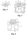
- FIGS. 4 to 6 illustrate a second embodiment of the insert.
- the insert 10 is generally identical to that of the first embodiment but includes a base wall 36 to enclose the air chamber 18.
- the base wall 36 comprises a bridge over the connecting rod small end bearing 32 to strengthen the base of the piston crown 24 and reduce the thickness of piston material at this point.
- the piston 12 so formed is of a similar weight to a conventional piston, but equally as strong.
- the air chamber is located centrally to and below the combustion chamber of the piston. It will be appreciated that the insert can be configured to provide other arrangements of air chamber with respect to combustion chamber.
Description
- The present invention relates to a method for producing a piston for an internal combustion (i.c.) engine and a piston produced by the method. In particular, the invention relates to a method for producing a piston of the type having a bowl-in-piston combustion chamber and an air chamber opening into the combustion chamber, said air chamber comprising an insert retained in the piston.
- It is known in a direct injection diesel engine to store a portion of hot compressed air from a compression stroke in an air chamber situated within a piston crown and to release this air into the piston combustion chamber during fuel combustion. This restricts oxygen supply for combustion during the early stages of combustion to limit noise and nitrous oxide emissions but increases oxygen supply towards the end of the combustion event when oxygen shortage would otherwise result in incomplete combustion and, therefore, the production of particulates.
- This is illustrated by SAE paper 952359, published October 1995, pages 147 to 158, in an article entitled "Modelling the Use of Air Injection for Emissions Reduction in a Direct Injected Diesel Engine", which describes the modelling of air injection for emissions reduction in direct injection diesel engines and compares the results for different air chamber configurations. It is concluded in the paper that the provision of an air chamber in a piston which releases air to the combustion chamber during fuel combustion reduces NOx, noise and particulate emissions. It is further concluded in the paper that an air chamber located below the piston combustion chamber having a certain configuration of transfer holes connecting the combustion chamber and the air chamber gives superior results to alternative geometries. However, the mechanical difficulties of providing an air chamber, or an insert comprising an air chamber, adjacent to a combustion chamber in a piston are not addressed.
- Similarly, GB 2184485A discloses a number of alternative constructions of air chamber inserts locatable within a crown of a piston adjacent to a combustion chamber but it does not teach a method of retaining such inserts in the piston crown.
- Such inserts are notoriously difficult to retain in place, the piston material being typically an aluminium alloy having a high coefficient of expansion and the piston, in use, being subjected to large temperature and pressure fluctuations.
- NL 9101258A does describe a method of retaining an insert in a piston crown. The insert is located within the piston crown generally below a piston combustion chamber and encloses an air chamber. One or more small holes in a wall of the insert connects the air chamber with the combustion chamber. Air is taken into and expelled from the air chamber in a manner similar to that of the present invention. The insert is provided with a flange contiguous with a face of the piston crown and is retained in position by bolts. The bolts may extend from the insert down into a cooler portion of the piston and this results in an increase in the mass of a lower part of the piston which affects piston reciprocation. The bolts also weaken the piston structure. Alternatively, the insert does not have a flange but is retained in the piston crown by freeze fitting. Both of these methods do not provide the integrity of assembly necessary to withstand the stresses that the piston will experience in use.
- The prior art mentioned above does not disclose a suitable method for locating and retaining an air chamber insert in a crown of a piston.
- DE 2136594, however, describes a method of retaining a metal alloy insert in a crown of a piston. The alloy of the insert is preferably a copper alloy. The insert locates around the mouth of the piston combustion chamber. The purpose of the insert is to reinforce a rim portion of the combustion chamber and protect it from the thermal stresses associated with fuel combustion. The insert is located as an integral part of the piston by casting the piston around the insert. During casting, the insert becomes welded to the material of the piston. The insert has a portion which projects beyond the piston crown which must be removed after the piston has been cast. The extending portion of the insert is provided as a means of positioning the insert prior to the piston being cast. A disadvantage of this method of insert placement is that it is only suitable where the top of the insert is to extend to the top surface of the piston crown.
- The retention of an apertured air chamber insert within a piston crown presents additional difficulties to those encountered in retaining combustion chamber lip reinforcing inserts. The air chamber insert is likely to be manufactured from a material dissimilar to that of the body of the piston which will present a problem relating to the difference in thermal expansion of the different materials. A further difficulty that will be encountered, in the case where the insert does not extend to the top surface of the piston crown, is the need to accurately position the insert relative to the piston die or mould.
- EP 0295481A discloses means of casting an insert into an aluminium alloy piston, the insert being an insulating crown of an iron-based or nickel-based alloy. However, no means is disclosed for configuring the insert as an air chamber and further, no means is disclosed to enhance the constructional integrity to enhance ability to durably withstand the severe pressure and temperature fluctuations likely to be encountered in a modern high-power-density diesel engine.
- It is an object of the present invention to provide a method for producing a piston for an internal combustion engine of the type having a bowl-in-piston combustion chamber and an air chamber opening thereinto, said air chamber comprising an insert retained in the piston crown.
- According to one aspect of the present invention, there is provided a method for producing a piston for an internal combustion (i.c.) engine, comprising the steps of: forming an insert; positioning said insert relative to a piston die or mould; and casting said piston in said die or mould; wherein the insert is positioned relative to the piston die or mould such that, when the piston is cast, the insert forms an integral part of the piston so formed, and said insert is formed such that it at least in part defines an air chamber opening into a combustion chamber formed within a crown of the piston.
- The method includes positioning the insert relative to the piston die or mould such that, when the piston is cast, a shoulder is formed which projects into the combustion chamber, said shoulder retaining the insert in the piston crown.
- The method may include forming the shoulder at or near a mouth of the combustion chamber.
- The method includes positioning the insert relative to the piston die or mould such that, when the piston is cast, it is located wholly within the piston crown.
- The method may include forming the insert such that a surface portion thereof forms at least a part of a surface comprising a combustion bowl bounding said combustion chamber.
- The method may include forming at least one aperture in the insert before casting the piston, said aperture intended to afford communication between the air chamber and the combustion chamber.
- Alternatively, the method may include forming the at least one aperture in the insert after the piston has been cast.
- The method may include forming the at least one aperture in the insert such that it opens on the surface portion thereof which forms at least a part of the combustion bowl.
- The method may include positioning the insert relative to the piston die or mould by means of a core of material which, once the piston has been cast, can be easily removed from the insert.
- The method may include contacting the core of material with the insert on the surface portion thereof which forms at least a part of the combustion bowl.
- The method may include attaching the insert to the core of material by placing said insert onto an end portion of said core such that the material of the core conforms to the shape of the surface portion of the insert to which it is attached.
- According to another aspect of the invention, there is provided a piston for an i.c. engine comprising: a piston body; a combustion bowl defining a combustion chamber formed in a crown of the piston body; an air chamber opening into the combustion chamber, said air chamber being bounded by an insert retained in the piston crown, the insert having at least one aperture affording communication between the air chamber and the combustion chamber, wherein the piston is cast such that it is integral with the insert.
- The insert is retained in the piston crown by a cast shoulder projecting into the combustion chamber.
- The shoulder may be located at or near a mouth of the combustion chamber.
- The insert is retained wholly within the piston crown.
- The insert may be shaped and positioned within the piston crown such that the air chamber is situated over a connecting rod small end bearing of the piston.
- The insert may be shaped such that the air chamber locates below the combustion chamber.
- The insert may be shaped such that the air chamber is located centrally with respect to the combustion chamber.
- The insert may be shaped such that an upper surface thereof defines a lower portion of the combustion bowl.
- The insert may include a base wall which, in use, provides a bridge over the connecting rod small end bearing of the piston.
- The insert may be formed from a thermally insulating material such as ceramic.
- Alternatively, the insert may be formed from a ferrous, copper or other metal alloy.
- The insert may be round in plan.
- The upper surface of the insert forming a bottom portion of the combustion bowl may be shaped so as to enhance swirl of air exiting the air chamber.
- The foregoing and further features of the present invention will be more readily understood from the following description of preferred embodiments, by way of example thereof, with reference to the accompanying drawings of which:
- Figure 1 is a cross-sectional elevation of a piston air chamber insert in accordance with a first embodiment of the invention;
- Figure 2 is a cross-sectional elevation of a piston incorporating the insert of figure 1;
- Figure 3 is a cross-sectional elevation of the insert of figure 1 located in a piston, said insert being carried on a core of material for holding said insert in position relative to a piston die or mould thus illustrating the method of the invention;
- Figure 4 is a cross-sectional elevation of a piston air chamber insert in accordance with a second embodiment of the invention;
- Figure 5 is a cross-sectional elevation of a piston incorporating the insert of figure 4;
- Figure 6 is a cross-sectional elevation of the insert of figure 4 located in a piston said insert being carried on a core of material holding said insert in position relative to a piston die or mould thus illustrating the method of the invention; and
-
- Reference will first be made to figures 1 to 3 of the drawings. Figure 1 is a cross-sectional elevation of a piston
air chamber insert 10 to be located within the body of a piston 12 (figure 2). Theinsert 10 is generally round in plan and comprises a centraldomed portion 14 surrounded by anupturned flange portion 16. The centraldomed portion 14 generally encloses anair chamber 18 although, in use, a base of theair chamber 18 will comprise a part of apiston 12 to be cast in situ around theinsert 10. Thedomed portion 14 has a number ofapertures 20 located radially around a central axis thereof. In use, theapertures 20 afford communication between theair chamber 18 and acombustion chamber 22 formed in acrown 24 of thepiston 12. Anupper surface 26 of theinsert 10 comprises, in use, a part of acombustion bowl 28 bounding thecombustion chamber 22 formed in thepiston crown 24. - The
air chamber 18 communicates with thecombustion chamber 22 via theapertures 20 which allow compressed air to pass into thechamber 18 during a piston compression stroke. The air in thechamber 18 is released to thecombustion chamber 22 during fuel combustion on the engine expansion stroke. In this way the amount of air, and thus oxygen, for fuel combustion is desirably restricted during the early stages of fuel combustion but augmented during the later stages of combustion. - The
insert 10 is retained in thepiston crown 24 by means of casting thepiston 12 around theinsert 10 such that theinsert 10 forms an integral part of thepiston 12. Theinsert 10 is retained in place by acast shoulder 30 which projects into thecombustion chamber 22 over theupturned flange part 16 of theinsert 10. The insert is wholly contained within thepiston crown 24. With the particular arrangement of the first embodiment, an advantage exists in that theair chamber 18 locates generally over a connecting rodsmall end bearing 32. This provides a degree of thermal insulation to protect said bearing 32 from the high temperatures occurring during fuel combustion. This reduces, and may even eliminate, the need for piston cooling means, such as oil jet cooling, to be included in the i.c. engine. - The insert may be formed from a metal alloy or ceramic. The material of the insert may diffusion bond with the metal of the piston on its being cast.
- The insert may be formed by the investment casting process or by any other suitable process which may be dictated by the material of the insert. The material of the insert may be chosen to have a lower coefficient of thermal expansion than the alloy of the piston body. The insert will thermally insulate the lower piston body from combustion heat and thus the expansion of the insert itself will be closer to that of the lower part of the piston crown than would be the case if some thermal protection was not provided by the insert.
- Figure 3 illustrates the method of positioning the insert with respect to a piston die or mould (not shown) prior to casting the piston (which is shown as cast) . The
insert 10 is positioned by carrying it on acore 34 of material which, in use, forms part of the piston die or mould. The insert is placed onto an end of the core such that the material of the core end conforms to theupper surface 26 of the insert. The remaining surface of the core 34 may be suitably shaped in readiness for piston casting such that said surface can determine part of the combustion chamber shape and reduce, if not eliminate, subsequent machining of thecombustion bowl 28. - In placing the
insert 10 on thecore 34 of the material, it is necessary to locate some core material 34a in the base of the insert to define theair chamber 18. This core material 34a can be removed from theair chamber 18 via theapertures 20 which may be formed during subsequent machining of thepiston crown 24 after the casting process. The material of the core may be any material suitable for casting and which can be easily cleaned from the piston and insert after casting. The material may be a leachable material such as salt which solidifies upon heating but can be dissolved and washed away with water upon completion of the casting process. - Figures 4 to 6 illustrate a second embodiment of the insert. Like numerals are used to denote like parts. The
insert 10 is generally identical to that of the first embodiment but includes abase wall 36 to enclose theair chamber 18. Thebase wall 36 comprises a bridge over the connecting rod small end bearing 32 to strengthen the base of thepiston crown 24 and reduce the thickness of piston material at this point. Thus, thepiston 12 so formed is of a similar weight to a conventional piston, but equally as strong. - When placing the
insert 10 on thecore 34 for positioning it with respect to the piston die or mould, it is necessary to ensure that the material of the core closes over anyapertures 20 in the upper wall of the insert if these have already been formed. Any core material which extends into theair chamber 18 can be easily removed after casting. - It will be seen that, with an insert configured in the manner illustrated in the embodiments, the air chamber is located centrally to and below the combustion chamber of the piston. It will be appreciated that the insert can be configured to provide other arrangements of air chamber with respect to combustion chamber.
Claims (19)
- A method for producing a piston (12) for an internal combustion (i.c.) engine, comprising the steps of: forming an insert (10); positioning said insert (10) relative to a piston die or mould; and casting said piston (12) in said die or mould; wherein the insert is positioned relative to the piston die or mould such that, when the piston is cast, the insert forms an integral part of the piston so formed, and said insert is formed such that it at least in part defines an air chamber (18) opening into a combustion chamber (22) formed within a crown (24) of the piston (12), wherein the method includes positioning the insert relative to the piston die or mould such that, when the piston is cast, a shoulder (30) is formed which projects into the combustion chamber (22), the insert (10) is located wholly within the piston crown (24) and is retained therein by said shoulder (30).
- A method as claimed in claim 1, wherein it includes forming the shoulder (30) at or near a mouth of the combustion chamber (22).
- A method as claimed in claim 1 or claim 2, wherein it includes forming an insert to comprise a central domed portion (14) surrounded by an upturned flange portion (16).
- A method as claimed in claim 3 wherein it includes positioning the insert relative to the piston die or mould such that, when the piston is cast, the shoulder (30) projects over the upturned flanged portion (16) of the insert (10).
- A method as claimed in any preceding claim, wherein it includes forming the insert such that a surface portion (26) thereof forms at least a part of a surface comprising a combustion bowl (28) bounding said combustion chamber (22).
- A method as claimed in any preceding claim, wherein it includes forming at least one aperture (20) in the insert before casting the piston, said aperture intended to afford communication between the air chamber and the combustion chamber.
- A method as claimed in any one of claims 1 to 5, wherein it includes forming the at least one aperture (20) in the insert after the piston has been cast.
- A method as claimed in any preceding claim, wherein it includes forming the at least one aperture in the insert such that it opens on a surface portion thereof (26) which forms at least a part of the combustion bowl (28).
- A method as claimed in any preceding claim, wherein it includes positioning the insert relative to the piston die or mould by means of a core (34) of material which, once the piston has been cast, can be easily removed from the insert.
- A method as claimed in claim 9, wherein it includes contracting the core of material with the insert on the surface portion thereof which forms at least a part of the combustion bowl.
- A method as claimed in claim 9 or 10, wherein it includes attaching the insert to the core of material by placing said insert onto an end portion of said core such that the material of the core conforms to the shape of the surface portion of the insert to which it is attached.
- A piston (12) for an i.c. engine comprising: a piston body; a combustion bowl (28) defining a combustion chamber (22) formed in a crown (24) of the piston body; an air chamber (18) opening into the combustion chamber, said air chamber being bounded by an insert (10) retained in the piston crown, the insert having at least one aperture (20) affording communication between the air chamber and the combustion chamber, wherein the piston is cast such that it is integral with the insert, and the insert is located wholly within the piston crown, and is retained therein by a cast shoulder (30) projecting into the combustion chamber (22).
- A piston as claimed in claim 12, wherein the shoulder (30) is located at or near a mouth of the combustion chamber (22).
- A piston as claimed in claim 12 or claim 13, wherein the insert comprises a central domed portion (14) surrounded by an upturned flanged portion (16).
- A piston as claimed in claim 14 wherein the shoulder (30) projects over the upturned flanged portion (16) of the insert.
- A piston as claimed in any one of claims 12 to 15, wherein the insert is configured such that a surface portion (26) thereof forms at least part of a surface comprising a combustion bowl (28) bounding said combustion chamber (22).
- A piston as claimed in claim 16 wherein the at least one aperture (20) in the insert (10) is formed such that it opens on the surface portion (26) of the insert which forms at least a part of the combustion bowl (28).
- A piston as claimed in any one of claims 12 to 17, wherein the insert is shaped and positioned within the piston crown such that the air chamber (18) is situated over a connecting rod small end bearing (32) of the piston.
- A piston as claimed in claim 19, wherein the insert includes a base wall (36) which, in use, provides a bridge over the connecting rod small end bearing (32) of the piston.
Applications Claiming Priority (2)
| Application Number | Priority Date | Filing Date | Title |
|---|---|---|---|
| GB9605838 | 1996-03-20 | ||
| GBGB9605838.3A GB9605838D0 (en) | 1996-03-20 | 1996-03-20 | A method for producing a piston for an internal combustion engine and a piston produced by the method |
Publications (4)
| Publication Number | Publication Date |
|---|---|
| EP0796687A2 EP0796687A2 (en) | 1997-09-24 |
| EP0796687A3 EP0796687A3 (en) | 1998-11-11 |
| EP0796687B1 EP0796687B1 (en) | 2001-01-31 |
| EP0796687B9 true EP0796687B9 (en) | 2001-08-22 |
Family
ID=10790705
Family Applications (1)
| Application Number | Title | Priority Date | Filing Date |
|---|---|---|---|
| EP97301176A Expired - Lifetime EP0796687B9 (en) | 1996-03-20 | 1997-02-24 | A method for producing a piston for an internal combustion engine and a piston produced by the method |
Country Status (7)
| Country | Link |
|---|---|
| US (1) | US5809962A (en) |
| EP (1) | EP0796687B9 (en) |
| JP (1) | JPH105976A (en) |
| KR (1) | KR970066033A (en) |
| CN (1) | CN1076995C (en) |
| DE (1) | DE69703995T2 (en) |
| GB (1) | GB9605838D0 (en) |
Families Citing this family (26)
| Publication number | Priority date | Publication date | Assignee | Title |
|---|---|---|---|---|
| DE19922809A1 (en) * | 1999-05-19 | 2000-11-23 | Mahle Gmbh | Casting process used in the production of pistons comprises producing recesses by cores that move on deformation |
| GB0015689D0 (en) * | 2000-06-28 | 2000-08-16 | Federal Mogul Technology Ltd | Manufacturing pistons |
| US6513476B1 (en) * | 2001-08-20 | 2003-02-04 | International Engine Inellectual Property Company, L.L.C. | Piston having combustion chamber defined in the crown |
| FR2837238B1 (en) * | 2002-03-15 | 2004-05-28 | Inst Francais Du Petrole | INTERNAL COMBUSTION ENGINE WITH FUEL INJECTION DEVICE |
| US8276563B2 (en) * | 2002-06-28 | 2012-10-02 | Cummins, Inc. | Internal combustion engine piston |
| US6705273B1 (en) | 2002-09-30 | 2004-03-16 | International Engine Intellectual Property Company, Llc | Combustion chamber |
| US6868817B2 (en) * | 2002-12-13 | 2005-03-22 | International Engine Intellectual Property Company, Llc | Simplified combustion chamber |
| US6955165B2 (en) | 2003-03-13 | 2005-10-18 | International Engine Intellectual Property Company, Llc | Three-reentrancy combustion chamber |
| US6945210B2 (en) * | 2003-09-29 | 2005-09-20 | International Engine Intellectual Property Company, Llc | Combustion chamber with one concave surface and three convex surfaces |
| US6935301B2 (en) * | 2003-12-01 | 2005-08-30 | International Engine Intellectual Property Company, Llc | Combustion chamber |
| US7104183B2 (en) * | 2004-07-07 | 2006-09-12 | Karl Schmidt Unisia, Inc. | One-piece steel piston |
| US6997158B1 (en) | 2004-10-07 | 2006-02-14 | International Engine Intellectual Property Company, Llc | Diesel combustion chamber |
| FR2925602A1 (en) * | 2007-12-19 | 2009-06-26 | Renault Sas | DISSYMMETRIC COMBUSTION CHAMBER FOR THERMAL ENGINE |
| DE102008031863A1 (en) * | 2008-07-05 | 2010-01-07 | Mahle International Gmbh | Insert for a piston of an internal combustion engine and provided with the insert piston or piston head |
| US20100108044A1 (en) * | 2008-11-06 | 2010-05-06 | International Engine Intellectual Property Company, Llc | Combustion Chamber with Double Convex Surfaces and Double Concave Surfaces |
| DE102011083994A1 (en) * | 2010-10-05 | 2012-04-05 | Ks Kolbenschmidt Gmbh | Improvements to a combustion bowl rim and to a combustion bowl bottom of a piston of an internal combustion engine |
| DE102011106391A1 (en) | 2011-07-02 | 2013-01-03 | Audi Ag | Piston for an internal combustion engine, method for producing a piston and internal combustion engine |
| DE102011107774A1 (en) * | 2011-07-15 | 2013-01-17 | Mahle International Gmbh | Piston for an internal combustion engine |
| US8800526B2 (en) | 2012-12-21 | 2014-08-12 | Caterpillar, Inc. | Instrumented piston for an internal combustion engine |
| US20160169152A1 (en) * | 2014-12-11 | 2016-06-16 | Caterpillar Inc. | Engine Piston |
| CN105484892A (en) * | 2015-12-02 | 2016-04-13 | 湖南江滨机器(集团)有限责任公司 | Piston, engine and piston manufacturing method |
| US10227949B2 (en) | 2016-12-23 | 2019-03-12 | Caterpillar Inc. | Piston for an internal combustion engine and method for producing said piston |
| CN107520404B (en) * | 2017-08-03 | 2019-06-14 | 日照市方进金属制品有限公司 | A kind of prefabricated metal part for evaporative pattern |
| DE102018123275A1 (en) * | 2018-09-21 | 2020-03-26 | Man Truck & Bus Se | Pistons for an internal combustion engine |
| CN111550325A (en) * | 2020-05-29 | 2020-08-18 | 滨州渤海活塞有限公司 | High-strength light internal combustion engine piston |
| CN113250846B (en) * | 2021-06-18 | 2022-08-16 | 中国北方发动机研究所(天津) | Combined high-strength heat insulation structure piston |
Family Cites Families (14)
| Publication number | Priority date | Publication date | Assignee | Title |
|---|---|---|---|---|
| GB315377A (en) * | 1928-07-13 | 1929-10-03 | Acro Ag | Improvements relating to the compression chambers of selfignition oil engines |
| US2662510A (en) * | 1950-12-18 | 1953-12-15 | Louis O French | Compression ignition internal-combustion engine |
| FR1244814A (en) * | 1960-01-11 | 1960-01-19 | Diesel motor | |
| DE2136594A1 (en) * | 1970-07-30 | 1972-02-03 | Mondial Piston Dott GaIh Ercole & C s p a , Turm (Italien) | Piston with an insert made of a metal alloy based on copper and surrounding the mouth of the combustion chamber |
| JPS5917248B2 (en) * | 1977-05-20 | 1984-04-20 | トヨタ自動車株式会社 | Internal combustion engine with auxiliary combustion chamber |
| GB2184485B (en) * | 1985-12-23 | 1989-10-11 | Ford Motor Co | Air cell for diesel engine combustion chamber |
| DE3719121A1 (en) * | 1987-06-06 | 1988-12-15 | Mahle Gmbh | Method for the production of an aluminium piston with fibre-reinforced areas for internal combustion engines |
| GB8714287D0 (en) * | 1987-06-18 | 1987-07-22 | Ae Plc | Pistons |
| DE3720865A1 (en) * | 1987-06-24 | 1989-01-05 | Opel Adam Ag | Air-compressing internal combustion engine, particularly a diesel engine |
| CA2024210A1 (en) * | 1989-11-06 | 1991-05-07 | William D. Guenther | Method of treating a ferrous component for subsequent metallurgical bonding to cast aluminum |
| JPH045428A (en) * | 1990-04-23 | 1992-01-09 | Isuzu Motors Ltd | Structure of combustion chamber of internal combustion engine |
| NL9101258A (en) * | 1991-07-18 | 1993-02-16 | Adolf Endert | Combustion engine and piston suitable for a combustion engine of this nature |
| JPH05141247A (en) * | 1991-11-18 | 1993-06-08 | Hino Motors Ltd | Piston for direct injection diesel engine |
| US5645028A (en) * | 1995-11-21 | 1997-07-08 | Isuzu Motors Limited | Piston structure with a combustion chamber |
-
1996
- 1996-03-20 GB GBGB9605838.3A patent/GB9605838D0/en active Pending
-
1997
- 1997-02-24 EP EP97301176A patent/EP0796687B9/en not_active Expired - Lifetime
- 1997-02-24 DE DE69703995T patent/DE69703995T2/en not_active Expired - Fee Related
- 1997-03-17 US US08/819,691 patent/US5809962A/en not_active Expired - Fee Related
- 1997-03-19 JP JP9066769A patent/JPH105976A/en active Pending
- 1997-03-19 CN CN97103327A patent/CN1076995C/en not_active Expired - Fee Related
- 1997-03-19 KR KR1019970009380A patent/KR970066033A/en not_active Application Discontinuation
Also Published As
| Publication number | Publication date |
|---|---|
| EP0796687A3 (en) | 1998-11-11 |
| GB9605838D0 (en) | 1996-05-22 |
| DE69703995D1 (en) | 2001-03-08 |
| EP0796687B1 (en) | 2001-01-31 |
| EP0796687A2 (en) | 1997-09-24 |
| DE69703995T2 (en) | 2001-08-23 |
| US5809962A (en) | 1998-09-22 |
| KR970066033A (en) | 1997-10-13 |
| CN1076995C (en) | 2002-01-02 |
| JPH105976A (en) | 1998-01-13 |
| CN1164612A (en) | 1997-11-12 |
Similar Documents
| Publication | Publication Date | Title |
|---|---|---|
| EP0796687B1 (en) | A method for producing a piston for an internal combustion engine and a piston produced by the method | |
| US5979298A (en) | Cooling gallery for pistons | |
| US4735128A (en) | Piston | |
| EP0118204B1 (en) | The reinforcement of pistons of aluminium or aluminium alloy | |
| US4972674A (en) | Heat insulating ceramic insert-cast articles for use in exhaust channels in internal combustion engines and a process for producing the same | |
| US8001946B2 (en) | Piston for an internal combustion engine and method for its production | |
| EP0807750B1 (en) | Cast piston having reinforced combustion bowl edge | |
| US4939984A (en) | Investment-cast piston crown cap with encapsulated non-metallic insulating core | |
| US4870733A (en) | Manufacturing method of a piston for an internal combustion engine | |
| US4920864A (en) | Reinforced piston | |
| US4687043A (en) | Composite casting process | |
| EP0410612B1 (en) | Heat-insulating structure of swirl chamber | |
| US4891875A (en) | Method for manufacturing a piston for an internal combustion engine | |
| EP0412659B1 (en) | Heat-insulating structure of swirl chamber and production method thereof | |
| JP3019529B2 (en) | Piston with combustion chamber | |
| EP0730085A1 (en) | A cylinder head and a method for producing a valve seat | |
| EP0410611A1 (en) | Heat-insulating structure of swirl chamber | |
| JPH04272455A (en) | Manufacutre of combustion chamber | |
| EP0468722A1 (en) | Ceramic-metal insert composite | |
| JP2623799B2 (en) | Internal combustion engine piston | |
| GB2209014A (en) | Piston | |
| JPH09209829A (en) | Piston for internal combustion engine | |
| JP2903742B2 (en) | Manufacturing method of combustion chamber | |
| JPH0118821Y2 (en) | ||
| JPH0114735Y2 (en) |
Legal Events
| Date | Code | Title | Description |
|---|---|---|---|
| PUAI | Public reference made under article 153(3) epc to a published international application that has entered the european phase |
Free format text: ORIGINAL CODE: 0009012 |
|
| AK | Designated contracting states |
Kind code of ref document: A2 Designated state(s): DE FR GB IT |
|
| PUAL | Search report despatched |
Free format text: ORIGINAL CODE: 0009013 |
|
| AK | Designated contracting states |
Kind code of ref document: A3 Designated state(s): DE FR GB IT |
|
| RAP1 | Party data changed (applicant data changed or rights of an application transferred) |
Owner name: PERKINS ENGINES COMPANY LIMITED |
|
| 17P | Request for examination filed |
Effective date: 19990419 |
|
| 17Q | First examination report despatched |
Effective date: 19990817 |
|
| GRAG | Despatch of communication of intention to grant |
Free format text: ORIGINAL CODE: EPIDOS AGRA |
|
| GRAG | Despatch of communication of intention to grant |
Free format text: ORIGINAL CODE: EPIDOS AGRA |
|
| GRAG | Despatch of communication of intention to grant |
Free format text: ORIGINAL CODE: EPIDOS AGRA |
|
| GRAH | Despatch of communication of intention to grant a patent |
Free format text: ORIGINAL CODE: EPIDOS IGRA |
|
| GRAH | Despatch of communication of intention to grant a patent |
Free format text: ORIGINAL CODE: EPIDOS IGRA |
|
| GRAA | (expected) grant |
Free format text: ORIGINAL CODE: 0009210 |
|
| ITF | It: translation for a ep patent filed |
Owner name: BARZANO' E ZANARDO MILANO S.P.A. |
|
| AK | Designated contracting states |
Kind code of ref document: B1 Designated state(s): DE FR GB IT |
|
| REF | Corresponds to: |
Ref document number: 69703995 Country of ref document: DE Date of ref document: 20010308 |
|
| ET | Fr: translation filed | ||
| PLBE | No opposition filed within time limit |
Free format text: ORIGINAL CODE: 0009261 |
|
| STAA | Information on the status of an ep patent application or granted ep patent |
Free format text: STATUS: NO OPPOSITION FILED WITHIN TIME LIMIT |
|
| REG | Reference to a national code |
Ref country code: GB Ref legal event code: IF02 |
|
| 26N | No opposition filed | ||
| PGFP | Annual fee paid to national office [announced via postgrant information from national office to epo] |
Ref country code: FR Payment date: 20060202 Year of fee payment: 10 |
|
| PGFP | Annual fee paid to national office [announced via postgrant information from national office to epo] |
Ref country code: IT Payment date: 20060228 Year of fee payment: 10 Ref country code: DE Payment date: 20060228 Year of fee payment: 10 |
|
| GBPC | Gb: european patent ceased through non-payment of renewal fee |
Effective date: 20070224 |
|
| REG | Reference to a national code |
Ref country code: FR Ref legal event code: ST Effective date: 20071030 |
|
| PG25 | Lapsed in a contracting state [announced via postgrant information from national office to epo] |
Ref country code: DE Free format text: LAPSE BECAUSE OF NON-PAYMENT OF DUE FEES Effective date: 20070901 |
|
| PG25 | Lapsed in a contracting state [announced via postgrant information from national office to epo] |
Ref country code: GB Free format text: LAPSE BECAUSE OF NON-PAYMENT OF DUE FEES Effective date: 20070224 Ref country code: FR Free format text: LAPSE BECAUSE OF NON-PAYMENT OF DUE FEES Effective date: 20070228 |
|
| PGFP | Annual fee paid to national office [announced via postgrant information from national office to epo] |
Ref country code: GB Payment date: 20060109 Year of fee payment: 10 |
|
| PG25 | Lapsed in a contracting state [announced via postgrant information from national office to epo] |
Ref country code: IT Free format text: LAPSE BECAUSE OF NON-PAYMENT OF DUE FEES Effective date: 20070224 |