EP0340141A1 - Mécanisme de frein électrique pour véhicules lourds - Google Patents
Mécanisme de frein électrique pour véhicules lourds Download PDFInfo
- Publication number
- EP0340141A1 EP0340141A1 EP89500018A EP89500018A EP0340141A1 EP 0340141 A1 EP0340141 A1 EP 0340141A1 EP 89500018 A EP89500018 A EP 89500018A EP 89500018 A EP89500018 A EP 89500018A EP 0340141 A1 EP0340141 A1 EP 0340141A1
- Authority
- EP
- European Patent Office
- Prior art keywords
- magnetic
- bearings
- carcass
- necks
- pinions
- Prior art date
- Legal status (The legal status is an assumption and is not a legal conclusion. Google has not performed a legal analysis and makes no representation as to the accuracy of the status listed.)
- Withdrawn
Links
- 230000007246 mechanism Effects 0.000 title claims abstract description 18
- 210000003739 neck Anatomy 0.000 claims abstract description 19
- 230000005540 biological transmission Effects 0.000 claims description 4
- 230000000712 assembly Effects 0.000 claims description 3
- 238000000429 assembly Methods 0.000 claims description 3
- 210000005036 nerve Anatomy 0.000 claims description 3
- 230000003213 activating effect Effects 0.000 claims 1
- 230000008878 coupling Effects 0.000 claims 1
- 238000010168 coupling process Methods 0.000 claims 1
- 238000005859 coupling reaction Methods 0.000 claims 1
- 230000000717 retained effect Effects 0.000 claims 1
- 230000014759 maintenance of location Effects 0.000 description 7
- 239000000446 fuel Substances 0.000 description 3
- 238000004880 explosion Methods 0.000 description 2
- 230000006870 function Effects 0.000 description 2
- 230000002452 interceptive effect Effects 0.000 description 2
- 238000013021 overheating Methods 0.000 description 2
- 230000002093 peripheral effect Effects 0.000 description 2
- 238000009423 ventilation Methods 0.000 description 2
- 238000010521 absorption reaction Methods 0.000 description 1
- 238000005452 bending Methods 0.000 description 1
- 230000015556 catabolic process Effects 0.000 description 1
- 230000000295 complement effect Effects 0.000 description 1
- 230000000694 effects Effects 0.000 description 1
- 230000005389 magnetism Effects 0.000 description 1
- 210000000056 organ Anatomy 0.000 description 1
- 238000005057 refrigeration Methods 0.000 description 1
- 230000003014 reinforcing effect Effects 0.000 description 1
- 239000007787 solid Substances 0.000 description 1
- 230000003068 static effect Effects 0.000 description 1
Images

Classifications
-
- H—ELECTRICITY
- H02—GENERATION; CONVERSION OR DISTRIBUTION OF ELECTRIC POWER
- H02K—DYNAMO-ELECTRIC MACHINES
- H02K49/00—Dynamo-electric clutches; Dynamo-electric brakes
- H02K49/02—Dynamo-electric clutches; Dynamo-electric brakes of the asynchronous induction type
- H02K49/04—Dynamo-electric clutches; Dynamo-electric brakes of the asynchronous induction type of the eddy-current hysteresis type
- H02K49/046—Dynamo-electric clutches; Dynamo-electric brakes of the asynchronous induction type of the eddy-current hysteresis type with an axial airgap
-
- B—PERFORMING OPERATIONS; TRANSPORTING
- B60—VEHICLES IN GENERAL
- B60T—VEHICLE BRAKE CONTROL SYSTEMS OR PARTS THEREOF; BRAKE CONTROL SYSTEMS OR PARTS THEREOF, IN GENERAL; ARRANGEMENT OF BRAKING ELEMENTS ON VEHICLES IN GENERAL; PORTABLE DEVICES FOR PREVENTING UNWANTED MOVEMENT OF VEHICLES; VEHICLE MODIFICATIONS TO FACILITATE COOLING OF BRAKES
- B60T1/00—Arrangements of braking elements, i.e. of those parts where braking effect occurs specially for vehicles
- B60T1/02—Arrangements of braking elements, i.e. of those parts where braking effect occurs specially for vehicles acting by retarding wheels
- B60T1/06—Arrangements of braking elements, i.e. of those parts where braking effect occurs specially for vehicles acting by retarding wheels acting otherwise than on tread, e.g. employing rim, drum, disc, or transmission or on double wheels
- B60T1/062—Arrangements of braking elements, i.e. of those parts where braking effect occurs specially for vehicles acting by retarding wheels acting otherwise than on tread, e.g. employing rim, drum, disc, or transmission or on double wheels acting on transmission parts
-
- B—PERFORMING OPERATIONS; TRANSPORTING
- B60—VEHICLES IN GENERAL
- B60T—VEHICLE BRAKE CONTROL SYSTEMS OR PARTS THEREOF; BRAKE CONTROL SYSTEMS OR PARTS THEREOF, IN GENERAL; ARRANGEMENT OF BRAKING ELEMENTS ON VEHICLES IN GENERAL; PORTABLE DEVICES FOR PREVENTING UNWANTED MOVEMENT OF VEHICLES; VEHICLE MODIFICATIONS TO FACILITATE COOLING OF BRAKES
- B60T13/00—Transmitting braking action from initiating means to ultimate brake actuator with power assistance or drive; Brake systems incorporating such transmitting means, e.g. air-pressure brake systems
- B60T13/74—Transmitting braking action from initiating means to ultimate brake actuator with power assistance or drive; Brake systems incorporating such transmitting means, e.g. air-pressure brake systems with electrical assistance or drive
- B60T13/748—Transmitting braking action from initiating means to ultimate brake actuator with power assistance or drive; Brake systems incorporating such transmitting means, e.g. air-pressure brake systems with electrical assistance or drive acting on electro-magnetic brakes
Definitions
- the present invention relates to an electric brake mechanism for heavy vehicles, which can be applied to trucks to be used as a means of retention of this type of vehicle when descending slopes and can replace the normal brake of the vehicle thus preventing overheating and the non-use of said conventional brake.
- the magnetic force to be applied to the discs or flywheels is originated by magnetic coils which are mounted telescopically on a nucleus, closing this through a pole plate, in such a way that all the whole remains mounted on a support plate, carrying so many polar plates and, consequently, magnetic cores as it becomes necessary.
- the air circulation through the interior of the assembly is zero, and we give even me the case where the external or flying disc to which we must apply the magnetic forces originating from the cited set, incorporates wings which aim to produce ventilation, even if they do not act as a fan, and they try to create a vacuum inside the box which forms the support plate, and this results in a retention force which means that the truck, while it is operating normally and the electric brake is not applied, consumes enough fuel, since we are creating a vacuum in a closed box and without any air circulation, and this vacuum logically absorbed a quantity of energy which must be supplied by the engine of the vehicle and consequently lose it as yield born from it.
- the electric brake mechanism proposed by the invention was designed to solve these problems with full satisfaction, based for this on the same operating principles as that which corresponds to the utility model cited 275.521 of the same applicant, whenever '' by presenting a series of innovations with which any type of failure which occurs in the whole of the brake will not require that it be disassembled in relation to the axes of the vehicle, but by simply unscrewing covers, it is possible to access the entire internal mechanism, that is to say, where the crowns are provided, as well as the pinions and other elements. It is therefore not necessary to carry out the disassembly, with the consequent saving of time, economic costs, etc.
- the mechanism itself presents what can be considered as lateral faces, that is to say, those which are perpendicular to the front faces where the bearings are mounted, totally open by means of large orifices, and on these we have targeted respective circular parts which are extended by one of their faces in the corresponding neck for mounting the magnetic masses, while in the interior or opposite face, extensions have been provided with the shape two arms which have a parallel relationship between them and end in two cylinders or cylindrical parts aligned axially and in transverse direction with respect to the longitudinal axis, so that between each pair of cylindrical bodies or rings it remains in place piece to which the respective pinion meshes.
- the assembly or magnetic masses to activate the cited electric brake, or another type of brake it has a very simple structure mainly thanks to the particular configuration of the support plate of the magnetic assembly, that is to say, the magnetic coils with their corresponding cores for mounting them. this.
- This original support plate has a concentric and cylindrical neck of a considerable diameter, through which the assembly will be mounted to the general and static carcass of what forms the electric brake of the vehicle, while in the crown determined between said nucleus and the peripheral edge of the plate of which we are talking, a plurality of boxes have been provided corresponding to one of the faces, boxes which are circular and in which are housed the corresponding cores on which the magnetic coils are mounted, and these close with the respective pole plate.
- the mechanism forming the electric brake object of the invention which comprises a carcass (1) of essentially cylindrical configuration and which has two opposite mouths (2) on which mounts the respective tubular sleeves (3) in which we precisely housed the bearings (4) on which we mounted the respective vehicle wheels. That is to say, the ends of the tubular sleeves (3) form the mounting means of each axis and the bearings (4) determine the transmission means for the rotation of these wheels.
- the carcass (1) also has two large mouths (5) with a large diameter, as can be seen in Figure 1 itself, to each of which is added a piece of circular configuration (6), all with screws , so that these parts (6) are extended by its face considered as an outer face in a neck (7), while by its inner face they are extended by arms (8) in parallel relation to each other and end in respective rings or cylindrical portions (9) which form corresponding supports, as will be described later.
- the pinions mentioned (12) form part of an axis (13), to which the corresponding magnetic disc (14) is coupled which opposes, according to the parallel plane, the magnetic mass mounted on each outer neck (7) of the parts (6), all this in collaboration with a crown (15), the carcass (16), the rings (17), the ball bearings (18), etc., as can be seen in the figure with clarity.
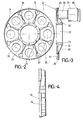
- the magnetic masses or assemblies have been mounted, which are formed from a support plate (21), of circular configuration and of small size, which has a large concentric orifice (22) from which a neck (23) is derived with orifices (24) for mounting the same on the cited neck (7) of the electric brake.
- This plate (21) has, in one of its faces, a plurality of grooves or boxes (25) of small depth and circular outline, so that in each of these boxes a core (26) has been mounted on which in turn showed a magnetic coil (27) which is closed with a pole plate (28).
- all the housings (25) will be supplied from the corresponding assembly forming the core (26), the magnetic coil (27) and the pole or closing plate (28), forming with the own plate ( 21) the magnetic assembly which will activate or act on the own brake disc or flywheel (14).
- the plate (21) has a peripheral groove (29), while between the recess or boxes (25) there are provided reinforcing nerves (30) as well as pass-through orifices (31), with an inner end rounded bevel (32), as seen in Figure 3.
- flywheel (14) coupled to the corresponding axis (13) of the braking mechanism, flywheel (14) provided by its rear part of a front (34) which is the one which remains precisely opposite to the plates polar or closing (28), so that when magnetism occurs, said front (33) is the one that will produce the braking of the flat or even flywheel (14) which, as it is united to the corresponding axis of the braking mechanism , will brake the wheels.
- the mechanism was mounted on the axes corresponding to the non-driving wheels of heavy vehicles, such as large tonnage trucks, so that these wheels will mount on the transmission bearings (4) and consequently on the sleeves. (3), precisely fixed to the general carcass (1) of the mechanism, allowing the rotation of said wheels as a consequence of the gears originating between the pinions (12) and the crowns (10).
Landscapes
- Engineering & Computer Science (AREA)
- Transportation (AREA)
- Mechanical Engineering (AREA)
- Power Engineering (AREA)
- Braking Arrangements (AREA)
Applications Claiming Priority (4)
| Application Number | Priority Date | Filing Date | Title |
|---|---|---|---|
| ES8801350U ES1005051Y (es) | 1988-04-29 | 1988-04-29 | Mecanismo de freno electrico para vehiculos pesados. |
| ES8801350 | 1988-04-29 | ||
| ES8803581 | 1988-12-02 | ||
| ES8803581U ES1008435Y (es) | 1988-12-02 | 1988-12-02 | Dispositivo magnetico de activacion del mecanismo de frenos electricos en vehiculos pesados. |
Publications (1)
| Publication Number | Publication Date |
|---|---|
| EP0340141A1 true EP0340141A1 (fr) | 1989-11-02 |
Family
ID=26154376
Family Applications (1)
| Application Number | Title | Priority Date | Filing Date |
|---|---|---|---|
| EP89500018A Withdrawn EP0340141A1 (fr) | 1988-04-29 | 1989-02-27 | Mécanisme de frein électrique pour véhicules lourds |
Country Status (2)
| Country | Link |
|---|---|
| EP (1) | EP0340141A1 (pt) |
| PT (1) | PT90403A (pt) |
Cited By (1)
| Publication number | Priority date | Publication date | Assignee | Title |
|---|---|---|---|---|
| CN104993670A (zh) * | 2015-04-24 | 2015-10-21 | 中国人民解放军装甲兵工程学院 | 一种车辆电涡流制动器 |
Citations (2)
| Publication number | Priority date | Publication date | Assignee | Title |
|---|---|---|---|---|
| FR1176326A (fr) * | 1958-05-06 | 1959-04-09 | Essieu de véhicule muni d'un ralentisseur électro-mécanique incorporé | |
| EP0059691A1 (en) * | 1981-03-03 | 1982-09-08 | Frenos Electricos Unidos S.A. | Improvements in vehicle axles provided with an incorporated electric brake |
-
1989
- 1989-02-27 EP EP89500018A patent/EP0340141A1/fr not_active Withdrawn
- 1989-04-28 PT PT9040389A patent/PT90403A/pt not_active Application Discontinuation
Patent Citations (2)
| Publication number | Priority date | Publication date | Assignee | Title |
|---|---|---|---|---|
| FR1176326A (fr) * | 1958-05-06 | 1959-04-09 | Essieu de véhicule muni d'un ralentisseur électro-mécanique incorporé | |
| EP0059691A1 (en) * | 1981-03-03 | 1982-09-08 | Frenos Electricos Unidos S.A. | Improvements in vehicle axles provided with an incorporated electric brake |
Cited By (2)
| Publication number | Priority date | Publication date | Assignee | Title |
|---|---|---|---|---|
| CN104993670A (zh) * | 2015-04-24 | 2015-10-21 | 中国人民解放军装甲兵工程学院 | 一种车辆电涡流制动器 |
| CN104993670B (zh) * | 2015-04-24 | 2017-11-17 | 中国人民解放军装甲兵工程学院 | 一种车辆电涡流制动器 |
Also Published As
| Publication number | Publication date |
|---|---|
| PT90403A (pt) | 1989-11-10 |
Similar Documents
| Publication | Publication Date | Title |
|---|---|---|
| US8220578B2 (en) | Construction kit and method for converting a bicycle, and bicycle | |
| EP0267953A1 (en) | DIFFERENTIAL GEARBOX. | |
| CN207790831U (zh) | 一种四轮独立驱动与转向电动车轮毂电机驱动独立集成化结构 | |
| CN110154737A (zh) | 一种低速大扭矩电动轮装置和电动汽车 | |
| TWM629063U (zh) | 電動助力自行車及其輪轂電機 | |
| EP0340141A1 (fr) | Mécanisme de frein électrique pour véhicules lourds | |
| CN105346668B (zh) | 无链自行车及其后轴组件 | |
| JPH04292284A (ja) | スイングアーム型電動二輪車 | |
| CN215186254U (zh) | 可快速拆卸轮毂及带轮胎的轮毂组件的轮毂电机 | |
| CN109606526B (zh) | 一种带横杆的u型悬挂系统 | |
| CN114261276A (zh) | 一种电动轮毂 | |
| CN211617979U (zh) | 一种空心轮毂自行车用增速装置及自行车 | |
| JPH04185532A (ja) | 減速機付ホィールモータ | |
| CN206242812U (zh) | 一种整体门式后驱动桥 | |
| FR2742937A1 (fr) | Dispositif d'entrainement d'un vehicule | |
| CN210364244U (zh) | 一种通用链传动差速器模块及自行车车轴 | |
| CN101618748A (zh) | 电动摩托车 | |
| CN206953989U (zh) | 一种乘用车辆的驱动机构 | |
| CN209466939U (zh) | 带横杆的u型悬挂系统 | |
| CN222657756U (zh) | 一种轮毂安装装置 | |
| CN211969078U (zh) | 一种电动车的一体化驱动桥 | |
| CN217124436U (zh) | 一种新式轮式挖掘机转向桥 | |
| DE102024000552B3 (de) | Reibrollenantrieb für Fahrzeuge, vorzugsweise für Fahrräder und Fahrradanhänger | |
| CN111336076B (zh) | 一种汽车助力发电系统 | |
| CN220523219U (zh) | 一种用于差速器总成的突缘总成机构 |
Legal Events
| Date | Code | Title | Description |
|---|---|---|---|
| PUAI | Public reference made under article 153(3) epc to a published international application that has entered the european phase |
Free format text: ORIGINAL CODE: 0009012 |
|
| AK | Designated contracting states |
Kind code of ref document: A1 Designated state(s): AT CH DE FR GR IT LI SE |
|
| 17P | Request for examination filed |
Effective date: 19900418 |
|
| 17Q | First examination report despatched |
Effective date: 19920225 |
|
| STAA | Information on the status of an ep patent application or granted ep patent |
Free format text: STATUS: THE APPLICATION IS DEEMED TO BE WITHDRAWN |
|
| 18D | Application deemed to be withdrawn |
Effective date: 19921007 |