EP0340141A1 - Electrical brake mechanism for heavy vehicles - Google Patents
Electrical brake mechanism for heavy vehicles Download PDFInfo
- Publication number
- EP0340141A1 EP0340141A1 EP89500018A EP89500018A EP0340141A1 EP 0340141 A1 EP0340141 A1 EP 0340141A1 EP 89500018 A EP89500018 A EP 89500018A EP 89500018 A EP89500018 A EP 89500018A EP 0340141 A1 EP0340141 A1 EP 0340141A1
- Authority
- EP
- European Patent Office
- Prior art keywords
- magnetic
- bearings
- carcass
- necks
- pinions
- Prior art date
- Legal status (The legal status is an assumption and is not a legal conclusion. Google has not performed a legal analysis and makes no representation as to the accuracy of the status listed.)
- Withdrawn
Links
- 230000007246 mechanism Effects 0.000 title claims abstract description 18
- 210000003739 neck Anatomy 0.000 claims abstract description 19
- 230000005540 biological transmission Effects 0.000 claims description 4
- 230000000712 assembly Effects 0.000 claims description 3
- 238000000429 assembly Methods 0.000 claims description 3
- 210000005036 nerve Anatomy 0.000 claims description 3
- 230000003213 activating effect Effects 0.000 claims 1
- 230000008878 coupling Effects 0.000 claims 1
- 238000010168 coupling process Methods 0.000 claims 1
- 238000005859 coupling reaction Methods 0.000 claims 1
- 230000000717 retained effect Effects 0.000 claims 1
- 230000014759 maintenance of location Effects 0.000 description 7
- 239000000446 fuel Substances 0.000 description 3
- 238000004880 explosion Methods 0.000 description 2
- 230000006870 function Effects 0.000 description 2
- 230000002452 interceptive effect Effects 0.000 description 2
- 238000013021 overheating Methods 0.000 description 2
- 230000002093 peripheral effect Effects 0.000 description 2
- 238000009423 ventilation Methods 0.000 description 2
- 238000010521 absorption reaction Methods 0.000 description 1
- 238000005452 bending Methods 0.000 description 1
- 230000015556 catabolic process Effects 0.000 description 1
- 230000000295 complement effect Effects 0.000 description 1
- 230000000694 effects Effects 0.000 description 1
- 230000005389 magnetism Effects 0.000 description 1
- 210000000056 organ Anatomy 0.000 description 1
- 238000005057 refrigeration Methods 0.000 description 1
- 230000003014 reinforcing effect Effects 0.000 description 1
- 239000007787 solid Substances 0.000 description 1
- 230000003068 static effect Effects 0.000 description 1
Images

Classifications
-
- H—ELECTRICITY
- H02—GENERATION; CONVERSION OR DISTRIBUTION OF ELECTRIC POWER
- H02K—DYNAMO-ELECTRIC MACHINES
- H02K49/00—Dynamo-electric clutches; Dynamo-electric brakes
- H02K49/02—Dynamo-electric clutches; Dynamo-electric brakes of the asynchronous induction type
- H02K49/04—Dynamo-electric clutches; Dynamo-electric brakes of the asynchronous induction type of the eddy-current hysteresis type
- H02K49/046—Dynamo-electric clutches; Dynamo-electric brakes of the asynchronous induction type of the eddy-current hysteresis type with an axial airgap
-
- B—PERFORMING OPERATIONS; TRANSPORTING
- B60—VEHICLES IN GENERAL
- B60T—VEHICLE BRAKE CONTROL SYSTEMS OR PARTS THEREOF; BRAKE CONTROL SYSTEMS OR PARTS THEREOF, IN GENERAL; ARRANGEMENT OF BRAKING ELEMENTS ON VEHICLES IN GENERAL; PORTABLE DEVICES FOR PREVENTING UNWANTED MOVEMENT OF VEHICLES; VEHICLE MODIFICATIONS TO FACILITATE COOLING OF BRAKES
- B60T1/00—Arrangements of braking elements, i.e. of those parts where braking effect occurs specially for vehicles
- B60T1/02—Arrangements of braking elements, i.e. of those parts where braking effect occurs specially for vehicles acting by retarding wheels
- B60T1/06—Arrangements of braking elements, i.e. of those parts where braking effect occurs specially for vehicles acting by retarding wheels acting otherwise than on tread, e.g. employing rim, drum, disc, or transmission or on double wheels
- B60T1/062—Arrangements of braking elements, i.e. of those parts where braking effect occurs specially for vehicles acting by retarding wheels acting otherwise than on tread, e.g. employing rim, drum, disc, or transmission or on double wheels acting on transmission parts
-
- B—PERFORMING OPERATIONS; TRANSPORTING
- B60—VEHICLES IN GENERAL
- B60T—VEHICLE BRAKE CONTROL SYSTEMS OR PARTS THEREOF; BRAKE CONTROL SYSTEMS OR PARTS THEREOF, IN GENERAL; ARRANGEMENT OF BRAKING ELEMENTS ON VEHICLES IN GENERAL; PORTABLE DEVICES FOR PREVENTING UNWANTED MOVEMENT OF VEHICLES; VEHICLE MODIFICATIONS TO FACILITATE COOLING OF BRAKES
- B60T13/00—Transmitting braking action from initiating means to ultimate brake actuator with power assistance or drive; Brake systems incorporating such transmitting means, e.g. air-pressure brake systems
- B60T13/74—Transmitting braking action from initiating means to ultimate brake actuator with power assistance or drive; Brake systems incorporating such transmitting means, e.g. air-pressure brake systems with electrical assistance or drive
- B60T13/748—Transmitting braking action from initiating means to ultimate brake actuator with power assistance or drive; Brake systems incorporating such transmitting means, e.g. air-pressure brake systems with electrical assistance or drive acting on electro-magnetic brakes
Definitions
- the present invention relates to an electric brake mechanism for heavy vehicles, which can be applied to trucks to be used as a means of retention of this type of vehicle when descending slopes and can replace the normal brake of the vehicle thus preventing overheating and the non-use of said conventional brake.
- the magnetic force to be applied to the discs or flywheels is originated by magnetic coils which are mounted telescopically on a nucleus, closing this through a pole plate, in such a way that all the whole remains mounted on a support plate, carrying so many polar plates and, consequently, magnetic cores as it becomes necessary.
- the air circulation through the interior of the assembly is zero, and we give even me the case where the external or flying disc to which we must apply the magnetic forces originating from the cited set, incorporates wings which aim to produce ventilation, even if they do not act as a fan, and they try to create a vacuum inside the box which forms the support plate, and this results in a retention force which means that the truck, while it is operating normally and the electric brake is not applied, consumes enough fuel, since we are creating a vacuum in a closed box and without any air circulation, and this vacuum logically absorbed a quantity of energy which must be supplied by the engine of the vehicle and consequently lose it as yield born from it.
- the electric brake mechanism proposed by the invention was designed to solve these problems with full satisfaction, based for this on the same operating principles as that which corresponds to the utility model cited 275.521 of the same applicant, whenever '' by presenting a series of innovations with which any type of failure which occurs in the whole of the brake will not require that it be disassembled in relation to the axes of the vehicle, but by simply unscrewing covers, it is possible to access the entire internal mechanism, that is to say, where the crowns are provided, as well as the pinions and other elements. It is therefore not necessary to carry out the disassembly, with the consequent saving of time, economic costs, etc.
- the mechanism itself presents what can be considered as lateral faces, that is to say, those which are perpendicular to the front faces where the bearings are mounted, totally open by means of large orifices, and on these we have targeted respective circular parts which are extended by one of their faces in the corresponding neck for mounting the magnetic masses, while in the interior or opposite face, extensions have been provided with the shape two arms which have a parallel relationship between them and end in two cylinders or cylindrical parts aligned axially and in transverse direction with respect to the longitudinal axis, so that between each pair of cylindrical bodies or rings it remains in place piece to which the respective pinion meshes.
- the assembly or magnetic masses to activate the cited electric brake, or another type of brake it has a very simple structure mainly thanks to the particular configuration of the support plate of the magnetic assembly, that is to say, the magnetic coils with their corresponding cores for mounting them. this.
- This original support plate has a concentric and cylindrical neck of a considerable diameter, through which the assembly will be mounted to the general and static carcass of what forms the electric brake of the vehicle, while in the crown determined between said nucleus and the peripheral edge of the plate of which we are talking, a plurality of boxes have been provided corresponding to one of the faces, boxes which are circular and in which are housed the corresponding cores on which the magnetic coils are mounted, and these close with the respective pole plate.
- the mechanism forming the electric brake object of the invention which comprises a carcass (1) of essentially cylindrical configuration and which has two opposite mouths (2) on which mounts the respective tubular sleeves (3) in which we precisely housed the bearings (4) on which we mounted the respective vehicle wheels. That is to say, the ends of the tubular sleeves (3) form the mounting means of each axis and the bearings (4) determine the transmission means for the rotation of these wheels.
- the carcass (1) also has two large mouths (5) with a large diameter, as can be seen in Figure 1 itself, to each of which is added a piece of circular configuration (6), all with screws , so that these parts (6) are extended by its face considered as an outer face in a neck (7), while by its inner face they are extended by arms (8) in parallel relation to each other and end in respective rings or cylindrical portions (9) which form corresponding supports, as will be described later.
- the pinions mentioned (12) form part of an axis (13), to which the corresponding magnetic disc (14) is coupled which opposes, according to the parallel plane, the magnetic mass mounted on each outer neck (7) of the parts (6), all this in collaboration with a crown (15), the carcass (16), the rings (17), the ball bearings (18), etc., as can be seen in the figure with clarity.
- the magnetic masses or assemblies have been mounted, which are formed from a support plate (21), of circular configuration and of small size, which has a large concentric orifice (22) from which a neck (23) is derived with orifices (24) for mounting the same on the cited neck (7) of the electric brake.
- This plate (21) has, in one of its faces, a plurality of grooves or boxes (25) of small depth and circular outline, so that in each of these boxes a core (26) has been mounted on which in turn showed a magnetic coil (27) which is closed with a pole plate (28).
- all the housings (25) will be supplied from the corresponding assembly forming the core (26), the magnetic coil (27) and the pole or closing plate (28), forming with the own plate ( 21) the magnetic assembly which will activate or act on the own brake disc or flywheel (14).
- the plate (21) has a peripheral groove (29), while between the recess or boxes (25) there are provided reinforcing nerves (30) as well as pass-through orifices (31), with an inner end rounded bevel (32), as seen in Figure 3.
- flywheel (14) coupled to the corresponding axis (13) of the braking mechanism, flywheel (14) provided by its rear part of a front (34) which is the one which remains precisely opposite to the plates polar or closing (28), so that when magnetism occurs, said front (33) is the one that will produce the braking of the flat or even flywheel (14) which, as it is united to the corresponding axis of the braking mechanism , will brake the wheels.
- the mechanism was mounted on the axes corresponding to the non-driving wheels of heavy vehicles, such as large tonnage trucks, so that these wheels will mount on the transmission bearings (4) and consequently on the sleeves. (3), precisely fixed to the general carcass (1) of the mechanism, allowing the rotation of said wheels as a consequence of the gears originating between the pinions (12) and the crowns (10).
Landscapes
- Engineering & Computer Science (AREA)
- Transportation (AREA)
- Mechanical Engineering (AREA)
- Power Engineering (AREA)
- Braking Arrangements (AREA)
Abstract
Description
La présente invention est rélative à un mécanisme de frein électrique pour véhicules lourds, qui peut être appliquée aux camions pour être utilisée comme moyen de rétention de ce type de véhicules en descendant des pentes et peut substituer le frein normal du véhicule ainsi empêchant le surchauffément et l'inutilisation du dit frein conventionnel.The present invention relates to an electric brake mechanism for heavy vehicles, which can be applied to trucks to be used as a means of retention of this type of vehicle when descending slopes and can replace the normal brake of the vehicle thus preventing overheating and the non-use of said conventional brake.
Les véhicules lourds, c'est-à-dire, ceux qui ont un grand tonnage, qui roulent en descendant des pentes, acquièrent une très élevée énergie cinétique, et ceci rend difficile de freiner ce type de véhicules, de sorte que, en utilisant les freins conventionnels, à cause de cette énorme énergie cinétique accumulée, il va se produire un surchauffément de ceux freins, même devenant inutilisables et en consequence devenant impossible de freiner totalement le véhicule.Heavy vehicles, that is, those with a large tonnage, which roll downhill, acquire very high kinetic energy, and this makes it difficult to brake this type of vehicle, so that, using conventional brakes, because of this enormous kinetic energy accumulated, there will occur an overheating of those brakes, even becoming unusable and consequently becoming impossible to brake the vehicle completely.
Pour éviter ces problèmes il est sorti au marché le frein électrique actuellement incorporé dans tous ceux véhicules lourds, freins électriques qui sont étrangers en leur fonctionnément et structure aux freins conventionnels étant donné que ceux-là agisent comme moteurs qui essayent de faire tourner en sens contraire à celui de la marche à des volants en rapport avec des axes des roues, généralement les axes derrières non-motrices.To avoid these problems, the electric brake currently incorporated in all those heavy vehicles has been released to the market, electric brakes which are foreign in their function and structure to conventional brakes since these act as motors which try to rotate in opposite directions. to that of walking with steering wheels in relation to the axes of the wheels, generally the rear non-driving axes.
Ces groupes électriques accomplissent la fonction pour laquelle ils ont été prévus d'une manière efficace. Cependant, et à cause des énormes efforts auxquels ils sont soumis, il se produit des fréquents cassements en des organes déterminés ou éléments qui forment partie des dits freins électriques, et il devient nécessaire pour éviter ce problème d'appliquer tous les efforts sur une seule couronne qui devait être évidemment surdimensionée pour empêcher le brisement.These electric groups perform the function for which they were intended in an efficient manner. However, and because of the enormous efforts to which they are subjected, frequent fractures occur in certain organs or elements which form part of the so-called electric brakes, and it becomes necessary to avoid this problem to apply all the efforts to a single crown which obviously had to be oversized to prevent breakage.
Après, des freins électriques sont sortis au marché fondés dans le principe dont on a parlé auparavant, c'est-à-dire, dans des masses magnétiques qui essayaient de faire tourner en sens contraire les axes des roues, ce qui provoquait le freinage; et ceux deuxièmes freins incorporaient deux couronnes pour pouvoir ainsi répartir les efforts.Afterwards, electric brakes came out to the market based on the principle that we talked about before, that is to say, in magnetic masses which tried to rotate the axes of the wheels in opposite directions, which caused braking; and those second brakes incorporated two crowns to be able to thus distribute the efforts.
Et bien, entre ces deuxièmes freins se trouve celui qu'on revendique dans le modèle d'utilité espagnol 275.521, du même demandant, de manière que structuralément dans le frein du dit modèle 275.521 on prévoyait que les manches correspondentes ou éléments tubulaires dans lesquels on loge les paliers mêmes sur lesquels montent les roues du véhicule, sont fixées à la carcasse centrale du dispositif même ou frein par des vis, exactément sur la partie frontale de ladite carcasse, et on prévoit aussi dans ce modèle d'utilité de souder sur les bouts des paliers des couronnes respectives engrenant perpendiculièment sur des pignons dont les axes ont les masses accouplées et celles-ci, oppossées aux bobines correspondants, provoquent l'effet de rétention du véhicule, parce-que lesdites masses magnétiques ont tendence à faire tourner en sens contraire les axes correspondants sur lesquels on a monté le frein même ou dispositif.Well, between these second brakes is the one claimed in the Spanish utility model 275.521, by the same applicant, so that structurally in the brake of the said model 275.521 it was expected that the corresponding sleeves or tubular elements in which houses the same bearings on which the vehicle wheels mount, are fixed to the central carcass of the same device or brake by screws, exactly on the front part of said carcass, and it is also provided in this utility model to weld on the ends of the bearings of the respective crowns meshing perpendicularly on pinions whose axes have coupled masses and these, opposite the corresponding coils, cause the retention effect of the vehicle, because said magnetic masses tend to rotate in direction otherwise the corresponding axes on which the same brake or device has been mounted.
En ce modèle on prévoit aussi que la carcasse ait des cous perpendiculiers au plan déterminé par les fronts du montage des paliers, ces cous n'étant pas en ligne, ce qu'empêchera que chaque pignon engrénant avec sa couronne respective interfiert avec l'autre.In this model, it is also expected that the carcass will have necks perpendicular to the plane determined by the fronts of the mounting of the bearings, these necks not being in line, which will prevent each pinion meshing with its respective crown from interfering with the other. .
Il n'y a aucune doute que cette structure de frein revendiquée dans le modèle d'utilité 275.521 offre une série d'avantages en référence avec les traditionnels, qui ont été commentés auparavant, comme c'est celle d'avoir les efforts répartis sur deux couronnes, ce que previent leur cassement, ainsi qu'une autre série d'avantages qu'à present ce n'est pas le cas de référer, mais qu'elle offre sans aucune doute.There is no doubt that this brake structure claimed in the utility model 275.521 offers a series of advantages in reference to the traditional ones, which have been commented on before, as is that of having the efforts distributed over two crowns, which prevents them from breaking, as well as another series of advantages which at present this is not the case to refer to, but which it undoubtedly offers.
Cependant, le problème qui presénte ce frein-ci c'est que, en cas de panne du même, il faut démonter tout l'ensemble des axes du camion, ce qui est coûteux, tant du point de vue économique comme du effort physique, et aussi lent, pour la considérable perte de temps qu'on se produit quand on fait des démontages tels.However, the problem that presents this brake is that, in the event of a breakdown of the same, it is necessary to dismantle all the axes of the truck, which is costly, both from the economic point of view and from physical effort, and also slow, for the considerable loss of time that occurs when doing such dismantling.
Dans ces types de freins électriques, la force magnétique à appliquer sur les disques ou volants est originée par des bobines magnétiques qui sont montées téléscopiquément sur un nucléus, fermant ceci à travers d'une plaque polaire, d'une manière telle que tout l'ensemble reste monté sur une plaque de support, porteuse de tant de plaques polaires et, par conséquence, de nucléus magnétiques comme il devient nécessaire.In these types of electric brakes, the magnetic force to be applied to the discs or flywheels is originated by magnetic coils which are mounted telescopically on a nucleus, closing this through a pole plate, in such a way that all the whole remains mounted on a support plate, carrying so many polar plates and, consequently, magnetic cores as it becomes necessary.
A cause de la structuration de ladite plaque de support et naturellement, de la conception de l'ensemble du dispositif magnetique cité, la circulation de l'air par l'intérieur de l'ensemble est nulle, et on donne mê me le cas où le disque extérieur ou volant auquel on doit appliquer les forces magnétiques originées par l'ensemble cité, incorpore des ailes qui ont pour but de produire une ventilation, même si elles n'agissent pas comme un ventilateur, et elles essayent de créer un vide à l'intérieur de la boîte qui forme la plaque de support, et ceci aboutit en une force de rétention qui fait que le camion, alors qu'il fonctionne normalement et le frein électrique n'est pas appliqué, consomme assez de combustible, étant donné qu'on est en train de créer un vide dans une boîte fermée et sans aucune circulation d'air, et ce vide logiquement absorbéra une quantité d'énergie qui doit être fournie par le moteur du véhicule et par conséquence le perdre comme rendement né de celui-ci.Because of the structure of said support plate and of course, the design of the assembly of the magnetic device cited, the air circulation through the interior of the assembly is zero, and we give even me the case where the external or flying disc to which we must apply the magnetic forces originating from the cited set, incorporates wings which aim to produce ventilation, even if they do not act as a fan, and they try to create a vacuum inside the box which forms the support plate, and this results in a retention force which means that the truck, while it is operating normally and the electric brake is not applied, consumes enough fuel, since we are creating a vacuum in a closed box and without any air circulation, and this vacuum logically absorbed a quantity of energy which must be supplied by the engine of the vehicle and consequently lose it as yield born from it.
En d'autres mots, qu'en rapport avec les dessins des ensembles magnétiques utilisés pour activer les dispositifs ou mécanismes correspondents aux freins électriques utilisés dans des véhicules lourds, on perd une grande quantité d'énergie, avec la conséquente diminution dans le rendement du véhicule et naturellement, une majeur consommation de combustible, et tout ceci, en plus, répercute sur les plaques de support en les courbant à cause de la manque de ventilation appropriée.In other words, that in relation to the designs of the magnetic assemblies used to activate the devices or mechanisms corresponding to the electric brakes used in heavy vehicles, a large amount of energy is lost, with the consequent decrease in the efficiency of the vehicle and naturally, a greater consumption of fuel, and all this, in addition, affects the support plates by bending them due to the lack of appropriate ventilation.
Le mécanisme de frein électrique proposé par l'invention a été conçu pour résoudre ces problèmes avec pleine satisfaction, en se basant pour ceci en les mêmes principes de fonctionnement que celui qui correspond au modèle d'utilité cité 275.521du même demandant, toute fois qu'en présentant une série d'innovations avec lesquelles n'importe quel type de panne qu'il se produisse dans l'ensemble du frein ne demandera pas qu'il soit démonté en rélation aux axes du véhicule, mais qu'en devissant tout simplement des couvercles, il est possible d'accéder à tout le mécanisme intérieur, c'est-à-dire, où l'on trouve les couronnes prévues, ainsi que les pignons et les autres éléments. Ce n'est pas donc nécessaire d'éfectuer le démontage, avec la conséquente économie de temps, des coûts économiques, etc.The electric brake mechanism proposed by the invention was designed to solve these problems with full satisfaction, based for this on the same operating principles as that which corresponds to the utility model cited 275.521 of the same applicant, whenever '' by presenting a series of innovations with which any type of failure which occurs in the whole of the brake will not require that it be disassembled in relation to the axes of the vehicle, but by simply unscrewing covers, it is possible to access the entire internal mechanism, that is to say, where the crowns are provided, as well as the pinions and other elements. It is therefore not necessary to carry out the disassembly, with the consequent saving of time, economic costs, etc.
D'une manière plus concrète, le mécanisme proprement dit présente ce qu'on peut considérer comme des faces latérales, c'est-à-dire, celles qui sont perpendiculières aux faces frontales où vont montés les paliers, totalement ouvertes par moyen d'amples orifices, et sur celles-ci on a visé des pièces circulaires respectives qui se prolonguent par une de leur faces en le cou correspondant pour le montage des masses magnétiques, alors que dans la face intérieur ou opposée on a prévu des prolongations avec la forme de deux bras qui ont un rapport paralel entre eux et finissent en deux frettes ou pièces cilindriques alignées axialément et en sens tranvérsale par rapport avec l'axe longitudinale, de forme qu'entre chaque paire de ceux corps cilindriques ou anneaux il reste en place la pièce à la qu'on engrène le pignon respectif.In a more concrete way, the mechanism itself presents what can be considered as lateral faces, that is to say, those which are perpendicular to the front faces where the bearings are mounted, totally open by means of large orifices, and on these we have targeted respective circular parts which are extended by one of their faces in the corresponding neck for mounting the magnetic masses, while in the interior or opposite face, extensions have been provided with the shape two arms which have a parallel relationship between them and end in two cylinders or cylindrical parts aligned axially and in transverse direction with respect to the longitudinal axis, so that between each pair of cylindrical bodies or rings it remains in place piece to which the respective pinion meshes.
Cette nouvelle conception structurelle du mécanisme ou frein électrique, permet qu'avec le seul démontage de cettes pièces complémentaires montées sur les latérales de la carcasse, on accède directement à tout le mécanisme intérieur, et on peut échanger les pièces inutilisées sans étre obligé de démonter tout l'ensemble en rapport avec les axes du camion, ni de l'emmener dans un atelier de réparations.This new structural design of the mechanism or electric brake, allows that with the only disassembly of these complementary parts mounted on the sides of the carcass, you can directly access the entire internal mechanism, and you can exchange the unused parts without having to disassemble the whole in relation to the axes of the truck, nor to take it to a repair shop.
D'un autre côté, en rélation avec l'ensemble ou masses magnétiques pour activer le frein électrique cité, ou un autre type de frein, elle présente une structure très simple grâce principalément à la particulière configuration de la plaque de support de l'ensemble magnétique, c'est-à-dire, des bobines magnétiques avec leurs correspondants nucléus de montage de celles-ci.On the other hand, in relation to the assembly or magnetic masses to activate the cited electric brake, or another type of brake, it has a very simple structure mainly thanks to the particular configuration of the support plate of the magnetic assembly, that is to say, the magnetic coils with their corresponding cores for mounting them. this.
Cette plaque de support originale présente un cou concentrique et cilindrique d'un diamètre considérable, à travers duquel on montera l'ensemble à la carcasse générale et statique de ce qui forme le frein électrique du véhicule, alors que dans la couronne determinée entre ledit nucléus et le bord périphérique de la plaque dont on parle on a prévu une pluralité de boîtés en correspondance avec une des faces, boîtés qui sont circulaires et dans lesquels sont logés les correspondants nucléus sur lesquels vont montés les bobines magnétiques, et celles-ci se ferment avec la plaque polaire respective.This original support plate has a concentric and cylindrical neck of a considerable diameter, through which the assembly will be mounted to the general and static carcass of what forms the electric brake of the vehicle, while in the crown determined between said nucleus and the peripheral edge of the plate of which we are talking, a plurality of boxes have been provided corresponding to one of the faces, boxes which are circular and in which are housed the corresponding cores on which the magnetic coils are mounted, and these close with the respective pole plate.
Entre ces boîtés de montage et les nucléus et bobines magnétiques respectives, il y a des nerfs intercalés pour le raidissement et des orifices à travers desquels il circuléra l'air.Between these mounting boxes and the cores and the respective magnetic coils, there are nerves interposed for the stiffening and orifices through which air circulated.
On a prévu aussi de la même façon et grâce à une particulière configuration du disque ou volant du frein, d'obténir un ensemble à travers duquel il est possible d'avoir une circulation intérieure d'air, permetant la réfrigération continuée des bobines magnétiques, ce qu'évitéra qu'elles n'atteignent les hautes températures dans les moments de freinage qu'elles normalément atteignent avec des dispositifs conventionnels, et prévenant avec ceci que les plaques de support ne se courbent comme il arrive à présent, ce qu'augmente le rendement de freinage grâce à la diminution de la température.We have also provided in the same way and thanks to a particular configuration of the disc or flywheel of the brake, to obtain an assembly through which it is possible to have an internal circulation of air, allowing continued refrigeration of the magnetic coils, which will prevent them from reaching the high temperatures in the braking moments which they normally reach with conventional devices, and preventing with this that the support plates do not bend as it now happens, which increases braking performance due to the decrease in temperature.
Il faut remarquer le fait que quand un véhicule lourd est en train de fonctionner normalément, c'est-à-dire, dans les moments de non-freinage, alors le volant ou disque n'est pas obligé de créer aucun type de vide dans la boîte formée dans les freins actuels, étant donné que ceux-ci sont hermétiquement fermés, et tout ceci aboutit dans une rétention pratiquement nulle parce-que le volant est en train d'absorber par ses propres moyens et d'une manière normale l'air à travers des orifices prévus dans la plaque de support, et il n'est pas forcé d'augmenter ou diminuer la consommation de combustible, ou de perdre de l'énergie pour créer ce vide ou celle absorption d'air, ce qu'en definitive, augmente le rendement du véhicule.It should be noted that when a heavy vehicle is operating normally, that is to say, in moments of non-braking, then the flywheel or disc is not obliged to create any type of vacuum in the box formed in the current brakes, since these are hermetically closed, and all this results in practically zero retention because the flywheel is absorbing by its own means and in a normal manner the air through holes provided in the support plate, and it is not forced to increase or decrease the consumption of fuel, or to lose energy to create this vacuum or that absorption of air, which ultimately, increases vehicle performance.
Pour compléter la description qu'on est en train de faire et à l'objet d'aider une méilleure compréhension des caractéristiques de l'invention, on accompagne à cette mémoire descriptive, comme partie intégrale de la même, une feuille unique de plans dans laquelle on a représenté avec caractère illustratif et non limitatif, le suivant:
- La figure 1.- Montre une représentation générale de la perspective, selon un dépiècement en explosion, du frein électrique objet de l'invention.
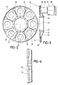
- La figure 2.- Montre une vue en plante de la plaque de support formant partie de l'ensemble magnétique correspondant au frein électrique de l'invention.
- La figure 3.- Montre une vue en coupe diamétrale de la plaque magnétique représentée dans la figure précédente, incluant en plus un nucléus avec la correspondante bobine et la plaque de fermeture en position de montage sur ladite plaque de support.
- La figure 4.- Montre, finalement, une vue latérale de ce que le disque ou volant de freinage est sur lequel agît précisément l'ensemble magnétique représenté dans les deux figures précédentes.
- Figure 1.- Shows a general representation of the perspective, according to an exploding explosion, of the electric brake object of the invention.
- Figure 2.- Shows a plant view of the support plate forming part of the magnetic assembly corresponding to the electric brake of the invention.
- Figure 3.- Shows a diametral section view of the magnetic plate shown in the previous figure, including a core with the corresponding coil and the closure plate in the mounting position on said support plate.
- Figure 4.- Finally shows a side view of what the brake disc or flywheel is on which acts precisely the magnetic assembly shown in the previous two figures.
A la vue des figures, en spéciale la figure 1, on peut observer le mécanisme formant le frein électrique objet de l'invention, qui comprend une carcasse (1) de configuration essentiellement cylindrique et qui possède deux bouches opposées (2) sur lesquelles on monte les respectives manches tubulaires (3) dans lesquelles on a logé précisément les paliers (4) sur lesquels on a monté les respectives roues du véhicule. C'est-à-dire, que les bouts des manches tubulaires (3) forment le moyen de montage de chaque axe et les paliers (4) determinent le moyen de transmission pour la rotation de cettes roues.In view of the figures, in particular Figure 1, we can observe the mechanism forming the electric brake object of the invention, which comprises a carcass (1) of essentially cylindrical configuration and which has two opposite mouths (2) on which mounts the respective tubular sleeves (3) in which we precisely housed the bearings (4) on which we mounted the respective vehicle wheels. That is to say, the ends of the tubular sleeves (3) form the mounting means of each axis and the bearings (4) determine the transmission means for the rotation of these wheels.
La carcasse (1) compte en plus avec deux grandes embouchures (5) d'un grand diamètre, comme on peut observer dans la figure 1 même, à chacune desquelles on ajoute une pièce de configuration circulaire (6), le tout avec des vis, de manière que cettes pièces (6) se prolonguent par sa face considérée come extérieure en un cou (7), alors que par sa face intérieure elles se prolonguent en des bras (8) en rapport parallèle entre eux et finissent en des anneaux respectifs ou des portions cylindriques (9) qui forment des supports correspondants, comme on décrira plus avant.The carcass (1) also has two large mouths (5) with a large diameter, as can be seen in Figure 1 itself, to each of which is added a piece of circular configuration (6), all with screws , so that these parts (6) are extended by its face considered as an outer face in a neck (7), while by its inner face they are extended by arms (8) in parallel relation to each other and end in respective rings or cylindrical portions (9) which form corresponding supports, as will be described later.
Les cous (7) des dites pièces circulaires (6) for ment à l'extérieur le moyen permettant de mettre en position les correspondantes masses magnétiques, restant celles-ci opposées à leurs respectifs disques magnétiques.The necks (7) of said circular parts (6) for ment outside the means for positioning the corresponding magnetic masses, remaining these opposite their respective magnetic disks.
Dans l'intérieur de la carcasse (1) restent logés les bras (8) des pièces circulaires (6) et en conséquence les frettes ou portions cylindriques (9). De la même façon, dans l'intérieur de cette carcasse (1) restent logées deux couronnes (10) opposées entr'elles et accouplées aux paliers (4) par des pièces ou couvettes (11) formant un ensemble solide. Ces couronnes (10) engrènent avec des pignons respectifs (12) sans interférer entr'eux-mêmes, comme conséquence de que lesdits pignons (12) ne gardent pas d'alinéation, ainsi que le montage des components associés à celui-ci.In the interior of the carcass (1) remain housed the arms (8) of the circular parts (6) and consequently the hoops or cylindrical portions (9). Similarly, in the interior of this carcass (1) remain housed two crowns (10) opposite to each other and coupled to the bearings (4) by parts or covers (11) forming a solid assembly. These crowns (10) mesh with respective pinions (12) without interfering with themselves, as a result of which said pinions (12) do not keep any alignment, as well as the mounting of the components associated with it.
Les pignons cités (12) forment partie d'un axe (13), auquel on accouple le correspondant disque magnétique (14)qui s'oppose, selon le plan parallèle, à la masse magnétique montée sur chaque cou extérieur (7) des pièces (6), tout ceci en collaboration avec une couronne (15), la carcasse (16), les anneaux (17), les roulements à boules (18), etc., comme on remarque dans la figure avec clarté.The pinions mentioned (12) form part of an axis (13), to which the corresponding magnetic disc (14) is coupled which opposes, according to the parallel plane, the magnetic mass mounted on each outer neck (7) of the parts (6), all this in collaboration with a crown (15), the carcass (16), the rings (17), the ball bearings (18), etc., as can be seen in the figure with clarity.
D'autre part, dans les portions cylindriques ou frettes (9) que celles-ci forment, on a monté des coussinets respectifs (19), chacun desquels va être mis en position avec la frette ou portion cylindrique correspondante (9), en se complétant avec des cerceaux (20).On the other hand, in the cylindrical portions or frets (9) that these form, there have been mounted respective bearings (19), each of which will be brought into position with the corresponding fret or cylindrical portion (9), complementing with hoops (20).
D'un autre côté, dans les cous (7) cités on a monté les masses ou ensembles magnétiques, lesquels sont constitués à partir d'une plaque de support (21), de configuration circulaire et de peu de grosseur, qui a un ample orifice concentrique (22) duquel on dérive un cou (23) avec des orifices (24) pour le montage de la même sur le cou cité (7) du frein électrique.On the other hand, in the necks (7) mentioned the magnetic masses or assemblies have been mounted, which are formed from a support plate (21), of circular configuration and of small size, which has a large concentric orifice (22) from which a neck (23) is derived with orifices (24) for mounting the same on the cited neck (7) of the electric brake.
Cette plaque (21) a, dans une de ses faces, une pluralité de canneléments ou boîtés (25) de petite profondeur et de contour circulaire, de forme qu'en chacun de ces boîtés on a monté un nucléus (26) sur lequel on montéra à son tour une bobine magnétique (27) qu'on ferme avec une plaque polaire (28).This plate (21) has, in one of its faces, a plurality of grooves or boxes (25) of small depth and circular outline, so that in each of these boxes a core (26) has been mounted on which in turn showed a magnetic coil (27) which is closed with a pole plate (28).
C'est-à-dire, tous les boîtements (25) seront fournis du correspondant ensemble formant le nucléus (26), la bobine magnétique (27) et la plaque polaire ou de fermeture (28), en formant avec la propre plaque (21) l'ensemble magnétique que fera activer ou agira sur le propre disque ou volant de freinage (14).That is to say, all the housings (25) will be supplied from the corresponding assembly forming the core (26), the magnetic coil (27) and the pole or closing plate (28), forming with the own plate ( 21) the magnetic assembly which will activate or act on the own brake disc or flywheel (14).
La plaque (21) compte avec un cannelément périphérique (29), alors qu'entre les recés ou boîtés (25) on a prévu des nerfs de renforçage (30) ainsi comme des orifices passants (31), avec une partie extrême intérieure en biseau arrondi (32), comme on voit sur la figure 3.The plate (21) has a peripheral groove (29), while between the recess or boxes (25) there are provided reinforcing nerves (30) as well as pass-through orifices (31), with an inner end rounded bevel (32), as seen in Figure 3.
Cette structuration permet que la plaque (21), avec tous ses éléments associés à la méme, puisse étre monté sur l'ensemble du dispositif de frein décrit auparavant, gráce à que celle-là compte avec des orifices (24) qui vont coïncider avec l'agraffément du frein méme et ainsi on pourra monter celui-ci, avec l a particularité que le cou (22) détermine un orifice ou passage d'un considérable diamètre où on accouple les cábles d'interconnéction entre les différentes bobines.This structuring allows that the plate (21), with all its elements associated with the same, can be mounted on the whole of the brake device described above, thanks to the fact that this one counts with orifices (24) which will coincide with even the brake and thus it can be mounted, with the particularity that the neck (22) determines an orifice or passage of a considerable diameter where the interconnection cables are coupled between the different coils.
Cet ensemble magnétique restera opposé, comme on a déjà indiqué, au disque ou volant (14) accouplé à l'axe correspondant (13) du mécanisme de freinage, volant (14) fourni par sa partie postérieur d'un front (34) qui est celui qui reste opposé précisament aux plaques polaires ou de fermeture (28), de sorte que quand le magnétisme se produit, ledit front (33) est celui qui produira le freinage du plat ou volant même (14) ce que, comme il est uni au correspondant axe du mécanisme de freinage, produira le freinage des roues.This magnetic assembly will remain opposite, as we has already indicated, to the disc or flywheel (14) coupled to the corresponding axis (13) of the braking mechanism, flywheel (14) provided by its rear part of a front (34) which is the one which remains precisely opposite to the plates polar or closing (28), so that when magnetism occurs, said front (33) is the one that will produce the braking of the flat or even flywheel (14) which, as it is united to the corresponding axis of the braking mechanism , will brake the wheels.
Selon la structuration décrite, on montéra le mécanisme sur les axes correspondants aux roues non-motrices des véhicules lourds, tels que des camions de grand tonnage, de sorte que cettes roues monteront sur les paliers de transmission (4) et en conséquence sur les manches (3), fixées précisement à la carcasse générale (1) du mécanisme, permettant la rotation des dites roues comme conséquence des engrenéments originés entre les pignons (12) et les couronnes (10).According to the structure described, the mechanism was mounted on the axes corresponding to the non-driving wheels of heavy vehicles, such as large tonnage trucks, so that these wheels will mount on the transmission bearings (4) and consequently on the sleeves. (3), precisely fixed to the general carcass (1) of the mechanism, allowing the rotation of said wheels as a consequence of the gears originating between the pinions (12) and the crowns (10).
Cependant, quand on veut activer ce mécanisme ou frein électrique, essayant de rétenir un véhicule en descendant des pentes, il suffira au chauffeur d'actionner le commande correspondant agissant sur les masses magnétiques disposées sur les cous (7), et cettes masses créeront une force magnétique et retendront aux disques magnétiques (14) et cette rétention se déplacéra à l'axe (13) et en conséquence aux pignons (12), et cette rétention répercutéra sur les couronnes (10) et en conséquence sur les paliers (4), étant donné que tout ceci est en rapport et engrené entre soi-même de la manière décrite, et tout ceci fait que cette rétention soit transmise logiquement aux roues du véhicule et que celui-ci s'arrête avec ce mécanisme, sans avoir bésoin d'utiliser les freins conventionnels ou normales.However, when we want to activate this mechanism or electric brake, trying to hold a vehicle downhill, it will be enough for the driver to activate the corresponding command acting on the magnetic masses placed on the necks (7), and these masses will create a magnetic force and will tighten with the magnetic discs (14) and this retention will move to the axis (13) and consequently to the pinions (12), and this retention will have repercussions on the crowns (10) and consequently on the bearings (4) , given that all of this is related to and intermeshed with oneself in the manner described, and all of this means that this retention is logically transmitted to the wheels of the vehicle and that the latter stops with this mechanism, without having to '' use conventional or normal brakes.
Claims (2)
Applications Claiming Priority (4)
| Application Number | Priority Date | Filing Date | Title |
|---|---|---|---|
| ES8801350U ES1005051Y (en) | 1988-04-29 | 1988-04-29 | ELECTRIC BRAKE MECHANISM FOR HEAVY VEHICLES. |
| ES8801350 | 1988-04-29 | ||
| ES8803581 | 1988-12-02 | ||
| ES8803581U ES1008435Y (en) | 1988-12-02 | 1988-12-02 | MAGNETIC DEVICE FOR ACTIVATING THE ELECTRIC BRAKE MECHANISM IN HEAVY VEHICLES. |
Publications (1)
| Publication Number | Publication Date |
|---|---|
| EP0340141A1 true EP0340141A1 (en) | 1989-11-02 |
Family
ID=26154376
Family Applications (1)
| Application Number | Title | Priority Date | Filing Date |
|---|---|---|---|
| EP89500018A Withdrawn EP0340141A1 (en) | 1988-04-29 | 1989-02-27 | Electrical brake mechanism for heavy vehicles |
Country Status (2)
| Country | Link |
|---|---|
| EP (1) | EP0340141A1 (en) |
| PT (1) | PT90403A (en) |
Cited By (1)
| Publication number | Priority date | Publication date | Assignee | Title |
|---|---|---|---|---|
| CN104993670A (en) * | 2015-04-24 | 2015-10-21 | 中国人民解放军装甲兵工程学院 | Vehicle eddy current brake |
Citations (2)
| Publication number | Priority date | Publication date | Assignee | Title |
|---|---|---|---|---|
| FR1176326A (en) * | 1958-05-06 | 1959-04-09 | Vehicle axle fitted with a built-in electro-mechanical retarder | |
| EP0059691A1 (en) * | 1981-03-03 | 1982-09-08 | Frenos Electricos Unidos S.A. | Improvements in vehicle axles provided with an incorporated electric brake |
-
1989
- 1989-02-27 EP EP89500018A patent/EP0340141A1/en not_active Withdrawn
- 1989-04-28 PT PT9040389A patent/PT90403A/en not_active Application Discontinuation
Patent Citations (2)
| Publication number | Priority date | Publication date | Assignee | Title |
|---|---|---|---|---|
| FR1176326A (en) * | 1958-05-06 | 1959-04-09 | Vehicle axle fitted with a built-in electro-mechanical retarder | |
| EP0059691A1 (en) * | 1981-03-03 | 1982-09-08 | Frenos Electricos Unidos S.A. | Improvements in vehicle axles provided with an incorporated electric brake |
Cited By (2)
| Publication number | Priority date | Publication date | Assignee | Title |
|---|---|---|---|---|
| CN104993670A (en) * | 2015-04-24 | 2015-10-21 | 中国人民解放军装甲兵工程学院 | Vehicle eddy current brake |
| CN104993670B (en) * | 2015-04-24 | 2017-11-17 | 中国人民解放军装甲兵工程学院 | A kind of vehicle electric eddy current brake |
Also Published As
| Publication number | Publication date |
|---|---|
| PT90403A (en) | 1989-11-10 |
Similar Documents
| Publication | Publication Date | Title |
|---|---|---|
| US8220578B2 (en) | Construction kit and method for converting a bicycle, and bicycle | |
| EP0267953A1 (en) | DIFFERENTIAL GEAR. | |
| CN207790831U (en) | A kind of four motorized wheels drive stand-alone integratedization structure with wheel hub electric motor of electric vehicle is turned to | |
| CN110154737A (en) | A kind of electronic wheel apparatus of low-speed big and electric car | |
| TWM629063U (en) | Electrically assisting bicycle and hub motor thereof | |
| EP0340141A1 (en) | Electrical brake mechanism for heavy vehicles | |
| CN105346668B (en) | Chain-less bicycle and its rear axle assemblies | |
| JPH04292284A (en) | Swing arm type electric motor two wheeler | |
| CN215186254U (en) | Hub motor capable of quickly disassembling hub and hub assembly with tire | |
| CN109606526B (en) | U-shaped suspension system with cross rod | |
| CN114261276A (en) | Electric hub | |
| CN211617979U (en) | Speed increasing device for hollow hub bicycle and bicycle | |
| JPH04185532A (en) | Wheel motor with decelerator | |
| CN206242812U (en) | A kind of overall gate-type rear driving axle | |
| FR2742937A1 (en) | VEHICLE DRIVE DEVICE | |
| CN210364244U (en) | Universal chain transmission differential module and bicycle axle | |
| CN101618748A (en) | Electric motorcycle | |
| CN206953989U (en) | A kind of drive mechanism of passenger vehicle | |
| CN209466939U (en) | U-shaped suspension with cross bar | |
| CN222657756U (en) | Hub mounting device | |
| CN211969078U (en) | Integrated drive axle of electric vehicle | |
| CN217124436U (en) | Novel steering axle of wheel type excavator | |
| DE102024000552B3 (en) | Friction roller drive for vehicles, preferably for bicycles and bicycle trailers | |
| CN111336076B (en) | Automobile power-assisted power generation system | |
| CN220523219U (en) | Flange assembly mechanism for differential assembly |
Legal Events
| Date | Code | Title | Description |
|---|---|---|---|
| PUAI | Public reference made under article 153(3) epc to a published international application that has entered the european phase |
Free format text: ORIGINAL CODE: 0009012 |
|
| AK | Designated contracting states |
Kind code of ref document: A1 Designated state(s): AT CH DE FR GR IT LI SE |
|
| 17P | Request for examination filed |
Effective date: 19900418 |
|
| 17Q | First examination report despatched |
Effective date: 19920225 |
|
| STAA | Information on the status of an ep patent application or granted ep patent |
Free format text: STATUS: THE APPLICATION IS DEEMED TO BE WITHDRAWN |
|
| 18D | Application deemed to be withdrawn |
Effective date: 19921007 |