DE102024000552B3 - Friction roller drive for vehicles, preferably for bicycles and bicycle trailers - Google Patents

Friction roller drive for vehicles, preferably for bicycles and bicycle trailers Download PDF

Info

Publication number
DE102024000552B3
DE102024000552B3 DE102024000552.8A DE102024000552A DE102024000552B3 DE 102024000552 B3 DE102024000552 B3 DE 102024000552B3 DE 102024000552 A DE102024000552 A DE 102024000552A DE 102024000552 B3 DE102024000552 B3 DE 102024000552B3
Authority
DE
Germany
Prior art keywords
friction roller
pressure
drive
roller
friction
Prior art date
Legal status (The legal status is an assumption and is not a legal conclusion. Google has not performed a legal analysis and makes no representation as to the accuracy of the status listed.)
Active
Application number
DE102024000552.8A
Other languages
German (de)
Inventor
gleich Patentinhaber Erfinder
Current Assignee (The listed assignees may be inaccurate. Google has not performed a legal analysis and makes no representation or warranty as to the accuracy of the list.)
Individual
Original Assignee
Individual
Priority date (The priority date is an assumption and is not a legal conclusion. Google has not performed a legal analysis and makes no representation as to the accuracy of the date listed.)
Filing date
Publication date
Application filed by Individual filed Critical Individual
Priority to DE102024000552.8A priority Critical patent/DE102024000552B3/en
Application granted granted Critical
Publication of DE102024000552B3 publication Critical patent/DE102024000552B3/en
Active legal-status Critical Current
Anticipated expiration legal-status Critical

Links

Images

Classifications

    • BPERFORMING OPERATIONS; TRANSPORTING
    • B62LAND VEHICLES FOR TRAVELLING OTHERWISE THAN ON RAILS
    • B62MRIDER PROPULSION OF WHEELED VEHICLES OR SLEDGES; POWERED PROPULSION OF SLEDGES OR SINGLE-TRACK CYCLES; TRANSMISSIONS SPECIALLY ADAPTED FOR SUCH VEHICLES
    • B62M6/00Rider propulsion of wheeled vehicles with additional source of power, e.g. combustion engine or electric motor
    • B62M6/40Rider propelled cycles with auxiliary electric motor
    • B62M6/75Rider propelled cycles with auxiliary electric motor power-driven by friction rollers or gears engaging the ground wheel
    • BPERFORMING OPERATIONS; TRANSPORTING
    • B62LAND VEHICLES FOR TRAVELLING OTHERWISE THAN ON RAILS
    • B62KCYCLES; CYCLE FRAMES; CYCLE STEERING DEVICES; RIDER-OPERATED TERMINAL CONTROLS SPECIALLY ADAPTED FOR CYCLES; CYCLE AXLE SUSPENSIONS; CYCLE SIDE-CARS, FORECARS, OR THE LIKE
    • B62K23/00Rider-operated controls specially adapted for cycles, i.e. means for initiating control operations, e.g. levers, grips
    • B62K23/02Rider-operated controls specially adapted for cycles, i.e. means for initiating control operations, e.g. levers, grips hand actuated
    • BPERFORMING OPERATIONS; TRANSPORTING
    • B62LAND VEHICLES FOR TRAVELLING OTHERWISE THAN ON RAILS
    • B62LBRAKES SPECIALLY ADAPTED FOR CYCLES
    • B62L1/00Brakes; Arrangements thereof
    • B62L1/02Brakes; Arrangements thereof in which cycle wheels are engaged by brake elements
    • B62L1/04Brakes; Arrangements thereof in which cycle wheels are engaged by brake elements the tyre surfaces being engaged

Landscapes

  • Engineering & Computer Science (AREA)
  • Chemical & Material Sciences (AREA)
  • Combustion & Propulsion (AREA)
  • Transportation (AREA)
  • Mechanical Engineering (AREA)
  • Braking Arrangements (AREA)

Abstract

Reibrollenantrieb für Fahrzeuge mit einer kinematischen Befestigung des Reibrollenmotors, die es ermöglicht, sowohl vorwärts wie rückwärts anzutreiben als auch vorwärts wie rückwärts mit dem Reibrollenmotor zu bremsen.Friction roller drive for vehicles with a kinematic attachment of the friction roller motor, which enables both forward and reverse driving and forward and reverse braking with the friction roller motor.

Description

Reibrollenantriebe sind wegen ihrer Einfachheit, trotz prinzipieller technischer Unzulänglichkeiten, gern in die engere Wahl zu Antriebslösungen für Fahrzeuge im niedrigen Leistungsbereich gezogen worden. Preiswerte Fertigung und den Kunden zufriedenstellende Funktion und Zuverlässigkeit rechtfertigen eine solche Entscheidung. Ein Paradebeispiel ist der langanhaltende Verkaufserfolg der Velosolex, begrifflich als Synonym für Zweiräder dieser Bauart verwendet, mit einem einfachen, auf das Vorderrad einer Fahrradkonstruktion mittels Reibrolle wirkenden Zweitaktmotor versehen. Zu Beginn der Markteinführung ging es darum, breiten Bevölkerungsschichten unabhängige motorisierte Mobilität preiswert zu ermöglichen, was damals voll und ganz gelang. Heutige Fragestellungen, wie Vermeidung fossiler Kraftstoffe, Abgasfreiheit, Wirkungsgradoptimierung waren damals noch nicht so im Fokus der Diskussion wie heute. So hat sich mittlerweile die Entwicklung von der Verwendung von Verbrennungsmotoren abgewendet zugunsten breiter Anwendung elektrischer Antriebe. Das Ergebnis sind die heutigen Pedelecs, die heute den Platz der Velosolex einnehmen und gegenüber dieser sogar den Vorzug haben, zum Betreiben keiner Allgemeinen Betriebserlaubnis zu bedürfen sowie ohne Versicherungpflicht und Helmtragepflicht betrieben werden zu können. Reibrollenantriebe als Nischenlösungen sind in der Breite des industriellen Angebots fast verschwunden. Dominierend sind Radnabenmotoren als Direktläufer oder als Getriebemotoren mit Freilauf, sowie in stark zunehmendem Masse Tretlagermotoren. Ohne weiter auf deren konstruktive Eigenheiten einzugehen, lassen sich folgende geschilderten Vor- und Nachteile benennen. Direktläufer haben großes Gewicht und lassen keine Verwendung von Trommelbremsen und im Hinterrad keine Nabenschaltung zu. Dafür kann mit ihnen Motorbremsung, sogar mit rekuperativer Energierückgewinnung durchgeführt werden, was mit modernen am Markt erhältlichen Kontrollern Stand der Technik ist. Nabenmotoren mit Getriebe und Freilauf sind nicht ganz so schwer wie Direktläufer, lassen auch keine Verwendung von Trommelbremsen und Nabenschaltungen zu und auch keine Motorbremsung. Tretlagermotoren lassen ebenfalls keine Motorbremsung zu. Bei Ihnen addiert sich der motorisch erzeugte Kettenzug zu dem durch Pedalieren erzeugten, was zu erhöhter Belastung und erhöhtem Verschleiß des Antriebsstranges führt. Im Gegensatz dazu wird mit laufradtreibenden Motoren der Kettenzug beim Pedalieren vermindert. Zusätzlich besteht noch der Vorteil, dass auch mit gerissener Kette das Fahrzeug weiterbewegt werden kann. Parallel zu diesen weit verbreiteten Lösungen sind trotzdem Reibrollenantriebe entwickelt und auch gefertigt worden, weil deren einfache Nachrüstbarkeit und deren niedriges Gewicht bestechend sind. So sind in der EP 3535170 A1 ( WO 2018/082 774 A1 ), der EP 2834143 A1 sowie in dem vom Hersteller GP Motion GmbH unter der Bezeichnung add-e angebotenem Nachrüstsatz Lösungen bekannt, deren Wirksamkeit auf dem während des Antreibens selbstverstärkenden Anpressdruckes der Reibrolle an den Reibpartner beruht, bedingt durch entsprechend kinematisch ausgebildete Führung der Reibrolle. Die dafür verwendeten Motoren sind vorzugsweise fremdkommutierte, kollektorfreie Außenläufermotoren, deren Außenläufer oder Teile davon als Reibflächenträger Anwendung finden. Die dafür verwendeten Motoren, entsprechen in Bauweise, Größe und Leistung den Motoren, wie sie in Modellflug-Drohnen oder Flugmodellen zu finden sind. Diese Motoren sind ideal für axiale Belastung, wie sie bei Montage von Luftschrauben direkt an der Stirnfläche des zylinderförmigen Außenläufers wirksam wird. Außerdem bewirkt der Luftstrom der Schraube wegen der offenen Motorbauart leistungsproportionale Innenkühlung des Motors. Bei Anwendung für einen Reibrollenantrieb ist der Außenläufer radialer Belastung ausgesetzt, wofür diese Motoren in ihrer üblichen Bauform nicht ausgelegt sind und es fehlt auch die Innenkühlung durch den Propellerluftstrom. Eine Lösung dazu findet sich in der EP 2834143 A1 . Im Gegensatz zu Innenläufern umgibt den Rotor (2) kein umschließendes Gehäuse an dem der Motor problemlos ohne gekröpfte Schwenk-und Spanneinrichtungen montiert werden kann. Ein Traggestell, hier als Motorchassis (1) bezeichnet, nimmt Magnetspulen und Lagerung auf und ist von der Mantelfläche und der Stirnseite des rotierenden Außenläufers umgeben. So bleibt zur Montage nur die der rotierenden Stirnfläche gegenüberliegende feste Stirnfläche des Motorchassis (1) zur Montage. Wird der Außenläufer radial belastet, ergeben sich große Biegemomente und Verformungskräfte aufgrund des Hebelarms, der sich durch die notwendige gekröpfte Bauweise der Motorhalterung ergibt. Der alternativen Verwendung von Innenläufermotoren steht der Nachteil entgegen, dass die Antriebsleistung von einer relativ dünnen Welle auf das Reibrad (3) übertragen werden muss, statt direkt von dem Rotor (2) auf die Reibfläche. Ein zusätzlicher gravierender Nachteil, der bislang weiterer Verbreitung von Reibrollenantrieben entgegensteht, ist darin begründet, dass sich bislang offenbar nicht genügend funktionale Vorteile für Anwender und Hersteller ergeben um sich dieser Technik zu bedienen, wie z.B. rekuperatives Bremsen und elektrisch unterstütztes Rückwärtsrangieren, wenn es z.B.darum geht, ein Lastenrad rückwärts aus einer abschüssigen Garageneinfahrt zu bugsieren oder einen Schubanhänger als elektrisch unterstützte Handkarre zu benutzen. Dies wäre einfach zu ermöglichen, indem ein zweiter mit andruckverstärkender Kinematik versehener Reibrollenmotor in umgekehrter Wirkungsrichtung an anderer Stelle an das zu treibende Laufrad montiert wird und so mit funktionsentsprechender Steuerung in beiden Richtungen sowohl Fahrbetrieb als auch elektrische Nutzbremsung möglich ist. Damit sind allerdings die Vorteile geringen Gewichtes, preiswerter Motorausstattung und unauffällig eleganter optischer Erscheinung stark geschmälert. Weitere Reibrollenantriebe sind aus den Druckschriften JP S50- 49848 U , DE 35 32 993 A1 , JP S50- 16 657 U , JP S56- 82 686 A , JP H09- 267 789 A , EP 0 155 185 A2 , CN 2 01 800 859 U , DE 10 2012 205 841 A1 , EP 3 323 655 B1 , GB 2 453 039 A und CN 1 15 447 704 A zu entnehmen.Because of their simplicity, despite fundamental technical deficiencies, friction roller drives have often been shortlisted as drive solutions for vehicles in the low power range. Inexpensive production and satisfactory functionality and reliability for the customer justify such a decision. A prime example is the long-term sales success of the Velosolex, used as a synonym for two-wheelers of this type, with a simple two-stroke engine acting on the front wheel of a bicycle construction using a friction roller. At the beginning of the market launch, the aim was to provide independent motorized mobility to broad sections of the population at low cost, which was fully achieved at the time. Today's issues such as avoiding fossil fuels, freedom from emissions, and efficiency optimization were not as much in the focus of discussion then as they are today. Development has now turned away from the use of combustion engines in favor of widespread use of electric drives. The result is today's Pedelecs, which have taken the place of the Velosolex and even have the advantage over the latter of not requiring a general operating permit to operate and can be operated without the obligation to take out insurance or wear a helmet. Friction roller drives as niche solutions have almost disappeared from the broad industrial range. The dominant models are wheel hub motors as direct-drive or geared motors with freewheel, and to a rapidly increasing extent bottom bracket motors. Without going into their design features in more detail, the following advantages and disadvantages can be identified. Direct-drive motors are heavy and do not allow the use of drum brakes or hub gears in the rear wheel. However, they can be used for motor braking, even with recuperative energy recovery, which is state of the art with modern controllers available on the market. Hub motors with gears and freewheel are not quite as heavy as direct-drive motors, do not allow the use of drum brakes and hub gears and do not allow motor braking. Bottom bracket motors also do not allow motor braking. In these cases, the chain tension generated by the motor is added to that generated by pedaling, which leads to increased load and increased wear on the drive train. In contrast, with impeller-driven motors, the chain tension is reduced when pedaling. There is also the advantage that the vehicle can continue to move even if the chain is broken. In parallel to these widely used solutions, friction roller drives have been developed and manufactured because they are easy to retrofit and have a low weight. EP3535170A1 ( WO 2018/082 774 A1 ), the EP 2834143 A1 and in the retrofit kit offered by the manufacturer GP Motion GmbH under the name add-e, solutions are known whose effectiveness is based on the self-reinforcing contact pressure of the friction roller on the friction partner during driving, due to the corresponding kinematic guidance of the friction roller. The motors used for this are preferably externally commutated, collector-free external rotor motors, the external rotors or parts of them of which are used as friction surface carriers. The motors used for this correspond in design, size and performance to the motors found in model aircraft drones or model aircraft. These motors are ideal for axial loads, such as those that occur when propellers are mounted directly on the front face of the cylindrical external rotor. In addition, the air flow of the screw causes internal cooling of the motor that is proportional to the power due to the open motor design. When used for a friction roller drive, the external rotor is exposed to radial loads, for which these motors are not designed in their usual design, and there is also no internal cooling by the propeller air flow. A solution to this can be found in the EP 2834143 A1 In contrast to internal rotors, the rotor (2) is not surrounded by an enclosing housing on which the motor can be easily mounted without cranked pivoting and clamping devices. A support frame, referred to here as the motor chassis (1), accommodates magnetic coils and bearings and is surrounded by the outer surface and the front side of the rotating external rotor. This means that only the fixed front surface of the motor chassis (1) opposite the rotating front surface remains for assembly. If the external rotor is loaded radially, large bending moments and deformation forces arise due to the lever arm, which results from the necessary cranked design of the motor mount. The alternative use of internal rotor motors has the disadvantage that the drive power has to be transferred from a relatively thin shaft to the friction wheel (3), instead of directly from the rotor (2) to the friction surface. An additional serious disadvantage that has so far prevented the further spread of friction roller drives is that there are apparently not enough functional advantages for users and manufacturers to use this technology, such as regenerative braking and electrically assisted reversing, for example when it comes to maneuvering a cargo bike backwards out of a sloping garage entrance or using a push trailer as an electrically assisted handcart. This could be easily achieved by mounting a second friction roller motor with pressure-enhancing kinematics in the opposite direction of action at another location on the wheel to be driven, thus With appropriate control in both directions, both driving and electrical regenerative braking are possible. However, this greatly reduces the advantages of low weight, inexpensive motor equipment and unobtrusive, elegant appearance. Other friction roller drives are known from the publications JP S50-49848U , DE 35 32 993 A1 , JP S50- 16 657 U , JP S56-82 686 A , JP H09- 267 789 A , EP 0 155 185 A2 , CN 2 01 800 859 U , EN 10 2012 205 841 A1 , EP 3 323 655 B1 , GB 2 453 039 A and CN 1 15 447 704 A refer to.

Aufgabe der Erfindung ist es, die zuvor genannten Nachteile aus dem Stand der Technik zu überwinden. Deshalb ist eine Lösung anzustreben, die den Betrieb von Antrieb und Bremse in beide Richtungen mit der gleichen Anzahl Motoren gestattet, wie sie bislang für Antrieb in eine einzige Richtung ohne Motorbrems- Option benutzt werden.The object of the invention is to overcome the aforementioned disadvantages of the prior art. Therefore, a solution is sought that allows the operation of drive and brake in both directions with the same number of motors as have previously been used for drive in a single direction without motor braking option.

Die Aufgabe wird mit den Gegenständen mit den Merkmalen der unabhängigen Patentansprüche gelöst.The problem is solved with the subject matter having the features of the independent patent claims.

Behebung der beschriebenen Nachteile und Mängel wird erfindungsgemäß mit den folgend aufgezeigten Vorrichtungen und Maßnahmen gelöst.The described disadvantages and deficiencies are remedied according to the invention with the devices and measures shown below.

So zeigt 1 in schematischer Darstellung Lösungen zum Abfangen der Radialkräfte an der Reibrolle sowohl für einen Außenläufermotor 1a) als auch für einen Innenläufermotor 1b) mit einem auf die durch den Außenläufer oder die durch die Reibrolle ragende Motorwelle montierten Stützlager (4) versehen. in 1c) eine Aufsicht auf die Seite der Reibrolle. Der für das Stützlager (4) erforderliche Stützlagerrahmen (5) dient auch zur Befestigung des Motors an den erforderlichen Spann- und Schwenk-Vorrichtungen weil so große Kröpfungen im Kraftverlauf zum Abfangen des Reibrollen - Anpressdruckes vermieden werden. Ragt die Welle nicht genügend weit oder gar nicht heraus, kann das Stützlager (4) nach den technischen Regeln des Handwerks auf eine ausreichend feste angeschraubte Wellenverlängerung, z.B. auf einer Montageplatte mit Zentriervorrichtung sitzend, montiert werden.This shows 1 in schematic representation solutions for absorbing the radial forces on the friction roller for both an external rotor motor 1a) as well as for an internal rotor motor 1b) with a support bearing (4) mounted on the motor shaft extending through the external rotor or the friction roller. in 1c ) a view of the side of the friction roller. The support bearing frame (5) required for the support bearing (4) is also used to attach the motor to the required clamping and swiveling devices because this avoids large offsets in the force curve to absorb the friction roller contact pressure. If the shaft does not protrude far enough or not at all, the support bearing (4) can be mounted on a sufficiently firmly screwed shaft extension, e.g. on a mounting plate with a centering device, in accordance with the technical rules of the trade.

In 2 a ist dargestellt, wie eine Reibrolle (3) mit anpressdruck-verstärkender Montagevorrichtung, bestehend aus primärem Anpresshebel (12) und aus sekundärem Anpresshebel (13) auf der Lauffläche eines Reifens (6) in Vorwärtsrichtung arbeitet. Mit dem Seilzug (8) wird die Antriebseinheit am beweglichen Widerlager, das den primären Anpresshebel (12) und den sekundären Anpresshebel (13) verbindet, vom primären Anpresshebel (12) gegen die Lauffläche des Reifens (6) gedrückt. Dabei wird entweder die zwischen primärem Anpresshebel (12) und sekundärem Anpresshebel (13) wirkende Druckfeder (14) zusammengedrückt bis beide Anpresshebel (12; 13) aufeinanderliegen und eine Winkelstellung des primären Anpresshebels (12) zur Tangente durch den Reibrollen-Berührungspunkt erreicht ist, bei der beim Antreiben der Reibrolle (3) durch die auf das feste mit der Fahrzeugstruktur verbundene Widerlager (9) wirkende Reaktionskraft Selbstverstärkung der Anpresskraft erreicht wird. Oder für den Fall, dass in der Praxis die zu überwindende Federspannung stört, lässt sich ein Seilzug (8) gemäß 2c anbringen, mit dessen Betätigung dieses Problem behoben wird.In 2 a is shown how a friction roller (3) with a contact pressure-enhancing mounting device, consisting of a primary contact pressure lever (12) and a secondary contact pressure lever (13), works in a forward direction on the tread of a tire (6). Using the cable (8), the drive unit on the movable abutment, which connects the primary contact pressure lever (12) and the secondary contact pressure lever (13), is pressed by the primary contact pressure lever (12) against the tread of the tire (6). In this case, either the compression spring (14) acting between the primary pressure lever (12) and the secondary pressure lever (13) is compressed until both pressure levers (12; 13) lie on top of each other and an angular position of the primary pressure lever (12) to the tangent through the friction roller contact point is reached, in which self-reinforcing of the pressure force is achieved when the friction roller (3) is driven by the reaction force acting on the fixed abutment (9) connected to the vehicle structure. Or, in the event that the spring tension to be overcome is a problem in practice, a cable pull (8) can be used according to 2c which, when activated, will resolve this problem.

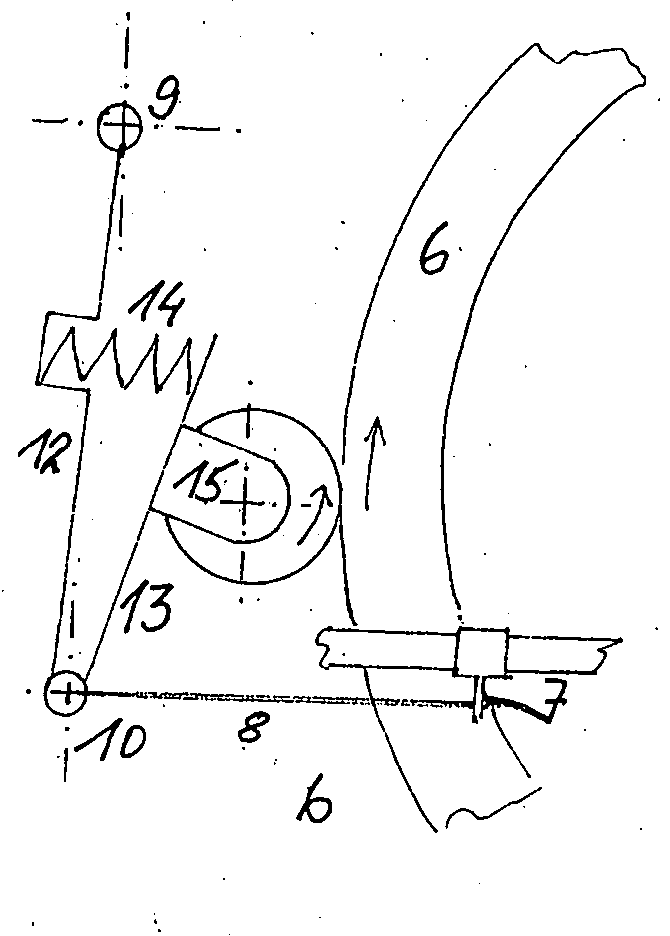
Beim Rückwärtsfahren oder Bremsen wird der den primären Anpresshebel (12) betätigende Seilzug (8) so weit entspannt, bis der sekundäre Anpresshebel (13) eine Stellung, evtl. an einem nicht dargestellten Anschlag, erreicht, bei der die Druckfeder (14) genügend Anpressdruck der Reibrolle (3) für schlupffreien Betrieb bereitstellt und gleichzeitig der sekundäre Anpresshebel (13) eine Winkelstellung zur Tangente durch den Berührungspunkt der Reibrolle erreicht, bei der Selbstverstärkung der Anpresskraft durch die von der Reibrolle in das bewegliche Widerlager (10) eingeleiteten Reaktionskraft erzielt wird. Funktional betrachtet nimmt jetzt das bewegliche Widerlager (10) die Funktion des festen Widerlagers (9) ein, wobei jetzt der primäre Anpresshebel (12) der festen Fahrzeugstruktur zuzurechnen ist. Also erfahren beide Anpresshebel beim Wechsel der Antriebs- oder Bremsrichtung einen Funktionswandel. So ist es möglich, einen Reibrollenantrieb bereitzustellen der in beiden Richtungen antreiben und mit dem Motor bremsen kann. Die zum problemfreien Betrieb erforderlichen Winkelstellungen der Anpresshebel müssen experimentell ermittelt werden. Sowohl verschleißfördernder Schlupf als auch durch zu große Anpresskaft bewirkte energiezehrende Walk- und Verformungsarbeit im Antrieb sind zu vermeiden.When reversing or braking, the cable (8) that actuates the primary pressure lever (12) is relaxed until the secondary pressure lever (13) reaches a position, possibly at a stop not shown, in which the compression spring (14) provides sufficient contact pressure of the friction roller (3) for slip-free operation and at the same time the secondary pressure lever (13) reaches an angular position to the tangent through the contact point of the friction roller, in which self-reinforcing of the contact force is achieved by the reaction force introduced by the friction roller into the movable abutment (10). From a functional point of view, the movable abutment (10) now takes on the function of the fixed abutment (9), whereby the primary pressure lever (12) is now part of the fixed vehicle structure. Both pressure levers therefore undergo a functional change when the drive or braking direction is changed. This makes it possible to provide a friction roller drive that can drive in both directions and brake with the motor. The angle positions of the contact pressure levers required for problem-free operation must be determined experimentally. Slippage, which promotes wear, as well as energy-consuming flexing and deformation work in the drive caused by excessive contact pressure must be avoided.

Alle diese Ausführungen gelten sinngemäß auch für den in 3 dargestellten Betrieb von zwei Reibrollenantrieben auf den Flanken einer Felge. 3a zeigt Antriebsstellung vorwärts oder Bremsstellung rückwärts. 3b zeigt Antriebsstellung rückwärts oder Bremsstellung vorwärts. Als feste Strukturen an einem Fahrrad zur Montage der festen Widerlager (9) erweisen sich entweder die Sattelstreben oder die Vorderradgabel als zweckmäßig.All these statements also apply to the 3 illustrated operation of two friction roller drives on the flanks of a rim. 3a shows drive position forward or brake position reverse. 3b shows the drive position backwards or the brake position forwards. Either the seat stays or the front wheel fork are suitable as fixed structures on a bicycle for mounting the fixed abutments (9).

Alle Seilzüge können manuell betätigt werden, in der Weise, dass mit der Betätigung auch ein Schaltelement zur pedelec-konformen Antriebsfunktion des Motors betätigt wird. Es können die Seilzüge (8) aber auch elektromagnetisch beim Einschalten des Antriebs betätigt werden. Diese mit einer Vorrichtung nach 8 schematisch dargestellte Möglichkeit ergibt sich fast gratis. Man stelle sich vor, eine Ader der Versorgungsleitung von der Batterie zum Kontroller (25) etwas länger zu machen und spiralförmig aufzuwickeln. Schon ergibt sich eine Magnetspule (28; 29), die vom gesamten zwischen Batterie und Kontroller (25) fließenden Strom durchströmt wird. Wegen Erfordernis möglichst kurzer Verbindung zwischen Batterie und Kontroller (25) empfiehlt es sich, dort auch die erforderlichen Magnetspulen (28; 29) einzufügen und die zu betätigenden Konstruktionsteile mit preiswerten Seilzügen durch Zuganker zu bewegen. Die erzielbare Zugkraft und damit der Rollenanpressdruck wächst proportional zur steigenden Motorleistung, zumindest bis zum Erreichen der magnetischen Sättigung, stetig an. Weil zwischen Batterie und Kontroller (25) immer nur Gleichstrom fließt, halten sich die Energieverluste durch Widerstandserhöhung in akzeptablen Grenzen. Wird ein Magnet als Anker benutzt, lässt sich mit einer Spule in zwei Richtungen wirken. Wird nicht vormagnetisiertes aber magnetisch aktivierbares Material wie z.B. Eisen verwendet, lässt sich mit zwei Magnetspulen (28; 29) gemäß Schaltung in 8 bei unterschiedlicher Stromflussrichtung getrennt wirken, was für den Wechsel zwischen Antreiben und rekuperativem Bremsen bedeutsam ist. 8 ist als schematisches Schaltbild zu verstehen. Die Funktion der Dioden kann auch von aktiven Leistungshalbleitern oder elektromechanischen Relais ausgeübt werden. Die Seilrolle nach Art eines Klappläufers in 9 bewirkt gleichmäßigen Anpressdruck der Antriebseinheiten (15) wenn zwei Motoren auf den Flanken einer Felge arbeiten sollen, wie in 3 dargestellt. Bei geringen Betätigungswegen kann zur Bewältigung großer Anpressdrücke eine mehrpartige Talje zur Übersetzung eingefügt werden. Es versteht sich von selbst, dass die Magnetspulen (28; 29) in Gehäusen solide mit dem Fahrzeug verbunden sein müssen um die Reaktionskräfte aufnehmen zu können. Wenn die Seilzüge (8) manuell aktiviert werden sollen, lassen sich die Magnetspulen (28; 29) auch als Haltemagneten einsetzen.All cables can be operated manually, in such a way that the operation also activates a switching element for the pedelec-compliant drive function of the motor. The cables (8) can also be operated electromagnetically when the drive is switched on. These are connected to a device according to 8th The possibility shown schematically is almost free. Imagine making one wire of the supply cable from the battery to the controller (25) a little longer and winding it up in a spiral. This creates a magnetic coil (28; 29) through which the entire current flowing between the battery and the controller (25) flows. Because the connection between the battery and the controller (25) needs to be as short as possible, it is recommended that the required magnetic coils (28; 29) be inserted there and that the structural parts to be actuated be moved using inexpensive cables through tie rods. The achievable pulling force and thus the roller contact pressure increases steadily in proportion to the increasing motor power, at least until magnetic saturation is reached. Because only direct current flows between the battery and the controller (25), the energy losses due to increased resistance remain within acceptable limits. If a magnet is used as an armature, one coil can act in two directions. If non-premagnetized but magnetically activatable material such as iron is used, two magnetic coils (28; 29) can be connected according to the circuit in 8th act separately when the current flow direction is different, which is important for switching between driving and regenerative braking. 8th is to be understood as a schematic circuit diagram. The function of the diodes can also be performed by active power semiconductors or electromechanical relays. The rope pulley in the form of a folding runner in 9 ensures uniform contact pressure of the drive units (15) when two motors are to work on the flanks of a rim, as in 3 shown. If the actuation distance is small, a multi-part tackle can be inserted to handle large contact pressures. It goes without saying that the magnetic coils (28; 29) must be solidly connected to the vehicle in housings in order to be able to absorb the reaction forces. If the cables (8) are to be activated manually, the magnetic coils (28; 29) can also be used as holding magnets.

In 4 ist dargestellt, wie mit zwei an den beweglichen Widerlagern (10) senkrecht über das Schutzblech (16) des Rades ragenden Streben beide Antriebseinheiten (15) mit einem einzigen Seilzug (8) gegen die Felge (17) gepresst werden.In 4 It is shown how both drive units (15) are pressed against the rim (17) with a single cable (8) using two struts on the movable abutments (10) that extend vertically above the mudguard (16) of the wheel.

5 und 6 zeigen eine Lösung, wie mit einer einzigen Antriebseinheit (15) ein Speichenrad für Fahrräder über die Felgenflanken mit Reibrollenantrieb angetrieben wird. Dadurch wird nicht nur ein Motor eingespart, sondern auch ein Kontroller (25). Ein aus Stützlagerrahmen (5) und an diesem mit mindestens einem biegesteifen, axialspielfreiem Rahmengelenk (21) mit mindestens einem Gelenkbolzen befestigten Andruckrahmen (19) gebildetes Antriebsgehäuse nimmt die Antriebseinheit (15) mit der Reibrolle (3) und an der gegenüberliegen Felgenflanke die Andruckrollen (18) auf. Der Antriebs- oder Bremsschub wird mit einem Kurbellenker (20) oder über ein Koppelgetriebe durch fest mit der Struktur des Fahrzeugs verbundene Widerlager (9) aufgenommen, wie hier beispielhaft als Lemniskatengetriebe in Form eines Wattgestänges (22) dargestellt. Sowohl Kurbellenker (20) als auch Wattgestänge (22) erlauben Drehung um die Hochachse. Dadurch ist eine Schiefstellung des Antriebsgehäuses während der Krafteinleitung der Reibrolle (3) in die Felge ermöglicht, mit der über das Rahmengelenk ( (21) das Antriebsgehäuse so verspannt wird, dass eine der Andruckrollen (18) die Antriebseinheit (15) gegen die Felge zieht. Um diese zum Antrieb erforderliche Schiefstellung zu bewirken, wird mit den beiden Seilzügen (8) je nach Fahrtrichtung das Antriebsgehäuse gegen die festen Widerlager verkantet. Das kann mechanisch über Handbedienung mit gekoppeltem Schalter für die Motorfunktion erfolgen oder mit Magnetspulen (28; 29) nach 8 mit der Zuganker ähnlich 9 betätigt werden. Dabei wird die Magnetspule Antrieb (28) beim Fahren aktiv, Magnetspule Bremsen / Rückwärtsfahren (29) eben beim Bremsen oder Rückwärtsfahren. Um das Antriebsgehäuse während des Betriebs richtig zur Felge zu positionieren und auch minimale Schräglaufeffekte durch die Rollen zu kompensieren, ist ein Gerätehalter mit Zentrierstrebe (23) vorgesehen, der zwar Drehung des Antriebsgehäuses um die in der Hochachse angebrachten Gelenkbolzen (24) erlaubt, aber dabei Reibrolle (3) und Andruckrollen (18) genau in der Tangentialebene der Abrollkreise positioniert. Dafür wird die quer zur Fahrtrichtung wegen des Ausgleichens minimaler Abstandsdifferenzen zur Felge (17) elastische Zentrierstrebe im Idealfall drehbar um die Radachse montiert, weil sich dadurch keine größeren messtechnischen Probleme für die Montage ergeben. Ist das nicht möglich, kann auch eine kinematische Ersatzkonstruktion gewählt werden mit der die geometrischen Erfordernisse erfüllt sind. 7 zeigt nach gleichem Prinzip einen Antrieb, der auf einer großen Bremsscheibe arbeitet. Das kann auch eine ringförmige Bremsscheibe sein,die außen an einer Felge montiert ist, auch bekannt unter der Bezeichnung „Perimeterscheibe“. Dann greift der Antrieb innen von der Nabenseite um die Scheibe. Die Funktion erfolgt genau wie anhand von 5 und 6 beschrieben, ergänzt durch den Vorteil kompakterer Bauweise. Trotz des geringeren Durchmessers von Bremsscheiben ergibt sich wegen der geringen Verformung und Walkarbeit im Gegensatz zu Reifen oder Felge mit entsprechend gewählter Reibflächenpaarung ein Antrieb, der in Wirkungsgrad, Leistungsvermögen, Gewicht, geringem Bauraum, rekuperativen Bremsvermögen und Rückfahrtauglichkeit allen bisher bekannten Ausführungen deutlich überlegen ist. 5 and 6 show a solution for how a spoked wheel for bicycles is driven via the rim flanks with a friction roller drive using a single drive unit (15). This not only saves a motor, but also a controller (25). A drive housing formed from a support bearing frame (5) and a pressure frame (19) attached to this with at least one rigid, axial play-free frame joint (21) with at least one joint bolt accommodates the drive unit (15) with the friction roller (3) and the pressure rollers (18) on the opposite rim flank. The drive or braking thrust is absorbed by a crank link (20) or via a coupling gear through abutments (9) firmly connected to the structure of the vehicle, as shown here as an example as a lemniscate gear in the form of a Watt linkage (22). Both the crank linkage (20) and the Watt linkage (22) allow rotation about the vertical axis. This allows the drive housing to be tilted when the friction roller (3) applies force to the rim, which clamps the drive housing via the frame joint (21) so that one of the pressure rollers (18) pulls the drive unit (15) against the rim. In order to achieve this tilt required for the drive, the two cables (8) tilt the drive housing against the fixed abutments depending on the direction of travel. This can be done mechanically via manual operation with a coupled switch for the motor function or with magnetic coils (28; 29) according to 8th with the tie rod similar 9 be operated. The drive solenoid (28) is activated when driving, and the braking/reversing solenoid (29) is activated when braking or reversing. In order to position the drive housing correctly in relation to the rim during operation and to compensate for minimal skew effects caused by the rollers, a device holder with a centering strut (23) is provided which allows the drive housing to rotate about the pivot pins (24) attached in the vertical axis, but positions the friction roller (3) and pressure rollers (18) exactly in the tangential plane of the rolling circles. For this purpose, the elastic centering strut, which is perpendicular to the direction of travel in order to compensate for minimal differences in distance to the rim (17), is ideally mounted so that it can rotate around the wheel axle, as this does not result in any major metrological problems during assembly. If this is not possible, a kinematic alternative design can be selected which meets the geometric requirements. 7 shows a drive that works on a large brake disc using the same principle. This can also be a ring-shaped brake disc that is mounted on the outside of a rim, also known as a "perimeter disc". The drive then grips the disc from the inside from the hub side. The function is exactly the same as with 5 and 6 described, supplemented by the advantage of a more compact design. Despite the smaller diameter of brake discs, the low deformation and flexing work in contrast to tires or rims with a correspondingly selected friction surface pairing results in a drive that is clearly superior to all previously known designs in terms of efficiency, performance, weight, small installation space, recuperative braking capacity and reversing capability.

BezugszeichenReference symbol

11
Motorgehäuse / MotorchassisEngine housing / engine chassis
22
Rotorrotor
33
ReibrollenFriction rollers
44
StützlagerSupport bearing
55
StützlagerrahmenSupport bearing frame
66
ReifenTires
77
BowdenzugwiderlagerBowden cable abutment
88th
SeilzugCable pull
99
festes Widerlagerfixed abutment
1010
bewegliches Widerlagermovable abutment
1111
Felgerim
1212
primärer Anpresshebelprimary pressure lever
1313
sekundärer Anpresshebelsecondary pressure lever
1414
DruckfederCompression spring
1515
AntriebseinheitDrive unit
1616
SchutzblechMudguard
1717
Felge (Schnitt)Rim (section)
1818
AndruckrollePressure roller
1919
Andruckrahmen/AndruckrollenrahmenPressure frame/pressure roller frame
2020
KurbellenkerCrank handlebar
2121
RahmengelenkFrame joint
2222
WattgestängeWatt rods
2323
Gerätehalter mit ZentrierstrebeDevice holder with centering strut
2424
GelenkbolzenArticulated bolt
2525
KontrollerController
2626
SteuerleitungControl line
2727
MotoranschlussMotor connection
2828
Magnetspule AntriebSolenoid drive
2929
Magnetspule Bremsen / RückwärtsfahrenMagnetic coil braking / reversing
3030
BremsscheibeBrake disc

Claims (5)

Reibrollenantrieb für Fahrzeuge, vorzugsweise Fahrräder und Fahrradanhänger, bestehend aus einem Antriebsmotor und einer mit einem Reibpartner (6; 11; 30) wirkenden Reibrolle (3) als Antriebseinheit (15), mit einem Kontroller (25) zur Steuerung und einer aufladbaren Batterie verbunden, sowie fest auf einem sekundären Anpresshebel (13) montiert, der wiederum durch ein Gelenk als ein in der Funktionsebene flächig im Raum bewegliches Widerlager (10) mit einem Ende des primären Anpresshebel (12) verbunden ist und an dessen anderen Ende sich ein weiteres fest mit der Fahrzeugstruktur verbundenes, nicht frei im Raum bewegliches Gelenk als festes Widerlager (9) befindet, dadurch gekennzeichnet, dass dieser Reibrollenantrieb in den vier Betriebszuständen Vorwärtsfahren, Rückwärtsfahren, Vorwärtsbremsen, Rückwärtsbremsen so auf die kinematische Anordnung der Anpresshebel (12; 13) einwirkt, dass immer Selbstverstärkung des Anpressdrucks zwischen Reibrolle (3) und Reibpartner (6; 11; 30) erfolgt, wobei zwischen dem primären Anpresshebel (12) und dem sekundären Anpresshebel (13) eine Druckfeder (14) angeordnet ist.Friction roller drive for vehicles, preferably bicycles and bicycle trailers, consisting of a drive motor and a friction roller (3) acting with a friction partner (6; 11; 30) as a drive unit (15), connected to a controller (25) for control and a rechargeable battery, and firmly mounted on a secondary pressure lever (13), which in turn is connected to one end of the primary pressure lever (12) by a joint as an abutment (10) that can be moved in space in the functional plane, and at the other end of which there is another joint that is firmly connected to the vehicle structure and cannot be moved freely in space as a fixed abutment (9), characterized in that this friction roller drive acts on the kinematic arrangement of the pressure levers (12; 13) in the four operating states of forward driving, reversing, forward braking, reversing braking in such a way that the contact pressure between the friction roller (3) and the friction partner (6; 11; 30) is always self-reinforced, whereby between a compression spring (14) is arranged between the primary pressure lever (12) and the secondary pressure lever (13). Reibrollenantrieb für Fahrzeuge, vorzugsweise Fahrräder und Fahrradanhänger, mit einer aufladbaren Batterie und einem Kontroller (25) verbunden, dadurch gekennzeichnet, dass mit mindestens einer vom gesamten zwischen Batterie und Kontroller (25) fließenden Strom durchflossenen Magnetspule (28; 29 ) ein magnetisch wirksamer Zuganker betätigt wird, der die für den Betriebsstart und den Betrieb erforderliche Anpresskraft der Reibrolle (3) an den Reibpartner (6; 11; 30) während des Vorwärtsfahrens, Rückwärtsfahrens, Vorwärtsbremsens, Rückwärtsbremsens bereitstellt oder mindestens als Haltemagnet nach manuellem Betriebsstart arbeitet.Friction roller drive for vehicles, preferably bicycles and bicycle trailers, connected to a rechargeable battery and a controller (25), characterized in that a magnetically effective tension rod is actuated by at least one magnetic coil (28; 29) through which the entire current flowing between the battery and the controller (25) flows, which provides the contact pressure of the friction roller (3) on the friction partner (6; 11; 30) required for starting and operating the vehicle during forward driving, reversing, forward braking, reversing braking or at least works as a holding magnet after manual starting of the vehicle. Reibrollenantrieb für Fahrzeuge, vorzugsweise Fahrräder und Fahrradanhänger, vorgesehen zum Antrieb an den Flanken einer Fahrradfelge (11), bestehend aus einem Stützlagerrahmen (5) mit Antriebseinheit (15) und Reibrolle (3), verbunden durch mindestens ein Rahmengelenk (21) mit einem Andruckrollenrahmen (19) der mindestens eine auf die der Reibrolle (3) gegenüberliegenden Felgenflanke wirkende Andruckrolle (18) aufnimmt, versehen mit einem quer zur Fahrtrichtung beweglichen mit der festen Fahrzeugstruktur verbundenen Widerlager (20; 22) zur Schubaufnahme, sowie von einem Gerätehalter (23) drehbar um die Hochachse so gehalten, dass sich Reibrolle (3) und die mindestens eine Andruckrolle (18) immer in der durch den vorgesehenen Berührungspunkt der Rollen (3; 18) auf der Felge laufenden tangentialen Funktionsebene befinden, dadurch gekennzeichnet, dass sich durch die Betätigung eines der Seilzüge (8) eine beim Wirken der Reibrolle( 3) auf der Felge (17) selbstverstärkende Schiefstellung der Vorrichtung um die Hochachse einstellt, die wiederum über das Rahmengelenk (21) Verspannen zum Andruckrollenrahmen (19) bewirkt, wodurch die Andruckrollen (18) die Antriebseinheit (15 ) mit Reibrolle (3) gegen die Felge (17) ziehen, mit der Folge selbstverstärkenden Anpressdruckes beim Vorwärtsfahren, Rückwärtsfahren, Vorwärtsbremsen und Rückwärtsbremsen.Friction roller drive for vehicles, preferably bicycles and bicycle trailers, intended for driving the flanks of a bicycle rim (11), consisting of a support bearing frame (5) with drive unit (15) and friction roller (3), connected by at least one frame joint (21) to a pressure roller frame (19) which accommodates at least one pressure roller (18) acting on the rim flank opposite the friction roller (3), provided with an abutment (20; 22) which is movable transversely to the direction of travel and connected to the fixed vehicle structure for absorbing thrust, and held by a device holder (23) so as to be rotatable about the vertical axis so that the friction roller (3) and the at least one pressure roller (18) are always in the tangential functional plane running through the intended point of contact of the rollers (3; 18) on the rim, characterized in that by operating one of the cable pulls (8) a self-reinforcing inclination when the friction roller (3) acts on the rim (17) the device is adjusted around the vertical axis, which in turn causes tensioning to the pressure roller frame (19) via the frame joint (21), whereby the pressure rollers (18) pull the drive unit (15) with friction roller (3) against the rim (17), with the result of self-reinforcing contact pressure when driving forwards, reversing, braking forwards and braking backwards. Reibrollenantrieb für Fahrzeuge, vorzugsweise Fahrräder und Fahrradanhänger, vorgesehen zum Antrieb auf einer Bremsscheibe (30), bestehend aus einem Stützlagerrahmen (5) mit Antriebseinheit (15) und Reibrolle (3), verbunden durch mindestens ein Rahmengelenk (21) mit einem Andruckrollenrahmen (19), der mindestens eine auf die der Reibrolle (3) gegenüberliegenden Seite der Bremsscheibe (30) wirkende Andruckrolle (18) aufnimmt, versehen mit einem quer zur Fahrtrichtung beweglichen Widerlager (20; 22) zur Schubaufnahme, sowie von einem Gerätehalter drehbar um die Hochachse so gehalten, dass sich Reibrolle (3) und Andruckrolle (18) immer auf den vorgesehenen Wirkungskreisen befinden, dadurch gekennzeichnet, dass sich durch die Betätigung eines der Seilzüge (8) eine beim Wirken der Reibrolle (3) auf der Bremsscheibe (30) selbstverstärkende Schiefstellung um die Hochachse einstellt, die wiederum über das Rahmengelenk (21) Verspannen zum Andruckrollenrahmen (19) bewirkt, wodurch die Andruckrollen (18) die Antriebseinheit (15) mit Reibrolle (3) gegen die Bremsscheibe (30) ziehen, mit der Folge selbstverstärkenden Anpressdruckes beim Vorwärtsfahren, Rückwärtsfahren, Vorwärtsbremsen und Rückwärtsbremsen.Friction roller drive for vehicles, preferably bicycles and bicycle trailers, intended for driving on a brake disc (30), consisting of a support bearing frame (5) with drive unit (15) and friction roller (3), connected by at least one frame joint (21) to a pressure roller frame (19) which accommodates at least one pressure roller (18) acting on the side of the brake disc (30) opposite the friction roller (3), provided with an abutment (20; 22) movable transversely to the direction of travel for absorbing thrust, and held by a device holder so as to be rotatable about the vertical axis so that the friction roller (3) and pressure roller (18) are always located on the intended spheres of action, characterized in that by operating one of the cables (8) a self-reinforcing inclination about the vertical axis is established when the friction roller (3) acts on the brake disc (30), which in turn causes tensioning to the pressure roller frame (19) via the frame joint (21), whereby the pressure rollers (18) Pull the drive unit (15) with friction roller (3) against the brake disc (30), resulting in self-reinforcing contact pressure when driving forwards, reversing, braking forwards and braking backwards. Reibrollenantrieb für Fahrzeuge, vorzugsweise Fahrräder und Fahrradanhänger, mit einer Antriebseinheit (15), die einen Reibrollenmotor in der Art eines Außenläufermotors enthält, dadurch gekennzeichnet, dass dieser Außenläufermotor an dem rotierenden geschlossenen Ende des zylinderförmigen Außenläufers ein zusätzliches Stützlager erhält, gehalten von einem Stützlagerrahmen (5) der die Montage mit ungekröpften Schwenk- und Spannvorrichtungen ermöglicht.Friction roller drive for vehicles, preferably bicycles and bicycle trailers, with a drive unit (15) which contains a friction roller motor in the manner of an external rotor motor, characterized in that this external rotor motor receives an additional support bearing at the rotating closed end of the cylindrical external rotor, held by a support bearing frame (5) which enables assembly with uncranked pivoting and clamping devices.
DE102024000552.8A 2024-02-19 2024-02-19 Friction roller drive for vehicles, preferably for bicycles and bicycle trailers Active DE102024000552B3 (en)

Priority Applications (1)

Application Number Priority Date Filing Date Title
DE102024000552.8A DE102024000552B3 (en) 2024-02-19 2024-02-19 Friction roller drive for vehicles, preferably for bicycles and bicycle trailers

Applications Claiming Priority (1)

Application Number Priority Date Filing Date Title
DE102024000552.8A DE102024000552B3 (en) 2024-02-19 2024-02-19 Friction roller drive for vehicles, preferably for bicycles and bicycle trailers

Publications (1)

Publication Number Publication Date
DE102024000552B3 true DE102024000552B3 (en) 2024-08-01

Family

ID=91852467

Family Applications (1)

Application Number Title Priority Date Filing Date
DE102024000552.8A Active DE102024000552B3 (en) 2024-02-19 2024-02-19 Friction roller drive for vehicles, preferably for bicycles and bicycle trailers

Country Status (1)

Country Link
DE (1) DE102024000552B3 (en)

Citations (16)

* Cited by examiner, † Cited by third party
Publication number Priority date Publication date Assignee Title
JPS5016657U (en) 1973-06-11 1975-02-21
JPS5049848U (en) 1973-09-05 1975-05-15
JPS5682686A (en) 1979-12-08 1981-07-06 Senya Yamanaka Bicycle
EP0155185A2 (en) 1984-03-15 1985-09-18 Alan Baker Electrically assisted cycle
DE3532993A1 (en) 1984-09-18 1986-03-27 Armin Bichwil Geiger Wheeled vehicle
DE9318528U1 (en) 1993-12-03 1994-08-11 Gohr, Rainer, 80804 München Retrofittable electric motor auxiliary drive for bicycles
JPH09267789A (en) 1996-03-29 1997-10-14 Shodenryoku Kogyo:Kk Auxiliary power transmitting method by tire contact driving system of manually driven vehicle, and transmission device for practicing the method
DE19633345A1 (en) 1996-08-07 1998-02-12 Guenter Rogee Compact battery-powered auxiliary electric motor drive for bicycle
CN2665001Y (en) 2003-12-11 2004-12-22 刘志宏 Bicycle power-driving device
GB2453039A (en) 2007-09-21 2009-03-25 Bear Corp Electric disk drive system for a bicycle
CN201800859U (en) 2010-09-03 2011-04-20 陈传生 Simple electric bicycle
DE102012006830A1 (en) 2012-04-03 2013-10-10 Peter Frieden Electromotive drive concept for bicycles
DE102012205841A1 (en) 2012-04-11 2013-10-17 Hochschule Heilbronn Drive system for driving two-wheeled vehicle, particularly hybrid propelled bicycle, has a drive unit attached to receptacle for brake caliper of brake disk, where drive plate is fixed on hub, and is in active connection with drive unit
WO2018082774A1 (en) 2016-11-03 2018-05-11 Karl Thiel Overrun brake actuation for a power trailer having a drawbar and wheels
EP3323655B1 (en) 2015-07-16 2021-09-01 Motordisc Electric Transmission, S.L. Transmission system for vehicles, and vehicle incorporating said transmission system.
CN115447704A (en) 2019-09-03 2022-12-09 双峰公司 Vehicle power auxiliary driving system

Patent Citations (18)

* Cited by examiner, † Cited by third party
Publication number Priority date Publication date Assignee Title
JPS5016657U (en) 1973-06-11 1975-02-21
JPS5049848U (en) 1973-09-05 1975-05-15
JPS5682686A (en) 1979-12-08 1981-07-06 Senya Yamanaka Bicycle
EP0155185A2 (en) 1984-03-15 1985-09-18 Alan Baker Electrically assisted cycle
DE3532993A1 (en) 1984-09-18 1986-03-27 Armin Bichwil Geiger Wheeled vehicle
DE9318528U1 (en) 1993-12-03 1994-08-11 Gohr, Rainer, 80804 München Retrofittable electric motor auxiliary drive for bicycles
JPH09267789A (en) 1996-03-29 1997-10-14 Shodenryoku Kogyo:Kk Auxiliary power transmitting method by tire contact driving system of manually driven vehicle, and transmission device for practicing the method
DE19633345A1 (en) 1996-08-07 1998-02-12 Guenter Rogee Compact battery-powered auxiliary electric motor drive for bicycle
CN2665001Y (en) 2003-12-11 2004-12-22 刘志宏 Bicycle power-driving device
GB2453039A (en) 2007-09-21 2009-03-25 Bear Corp Electric disk drive system for a bicycle
CN201800859U (en) 2010-09-03 2011-04-20 陈传生 Simple electric bicycle
DE102012006830A1 (en) 2012-04-03 2013-10-10 Peter Frieden Electromotive drive concept for bicycles
EP2834143A1 (en) 2012-04-03 2015-02-11 Velogical Engineering GmbH Electric drive for bicycles
DE102012205841A1 (en) 2012-04-11 2013-10-17 Hochschule Heilbronn Drive system for driving two-wheeled vehicle, particularly hybrid propelled bicycle, has a drive unit attached to receptacle for brake caliper of brake disk, where drive plate is fixed on hub, and is in active connection with drive unit
EP3323655B1 (en) 2015-07-16 2021-09-01 Motordisc Electric Transmission, S.L. Transmission system for vehicles, and vehicle incorporating said transmission system.
WO2018082774A1 (en) 2016-11-03 2018-05-11 Karl Thiel Overrun brake actuation for a power trailer having a drawbar and wheels
EP3535170A1 (en) 2016-11-03 2019-09-11 Karl Thiel Overrun brake actuation for a power trailer having a drawbar and wheels
CN115447704A (en) 2019-09-03 2022-12-09 双峰公司 Vehicle power auxiliary driving system

Similar Documents

Publication Publication Date Title
DE69700816T2 (en) Vehicle that can be operated with muscle power
DE60127462T2 (en) Strut, provided with drive means
EP0650886B1 (en) Bicycle gear change
DE2627603C3 (en) Bicycle with an auxiliary electric motor
EP2357128B1 (en) Drive orientation for a bicycle
DE102009052470B4 (en) Vehicle with an integrated motor
EP0079573A1 (en) Bicycle, in particular one with an electric motor
EP0988217A1 (en) Swinging arm motor unit for single-track or multiple-track electric motor driven vehicles
WO2011124415A1 (en) Drive device for a bicycle
DE102010060808A1 (en) Electric bicycle, has ball bearing fitted between fixed hollow hub and rotary wheel rim of wheel, and drive roller engaged with running surface in form-fit and friction-fit manner and connected with tire casing of bicycle tire of wheel
DE102010003926A1 (en) Wheeled vehicle with electric drive in the rear frame triangle
DE102019210720A1 (en) Connection system of a drive unit with a bicycle frame
DE102024000552B3 (en) Friction roller drive for vehicles, preferably for bicycles and bicycle trailers
DE10127769B4 (en) Drive assembly for a bicycle
DE3117415A1 (en) Vehicle with two or more wheels and with chainless drive
DE10309063A1 (en) Friction gear for an auxiliary unit arranged separately from an assembly belt drive of an internal combustion engine
DE102019113019A1 (en) BRAKE CONTROL DEVICE AND BRAKING SYSTEM
EP0555448B1 (en) Bicycle wheel hub with integral hub dynamo
CN212155583U (en) Electronic parking brake device with better sealing performance for drum brake
CN109873529B (en) Worm-helical gear transmission mechanism in double-boosting mechanism form for fitting load characteristics
DE102010004597A1 (en) Electrified roller with energy-efficient interlocking mechanism
CN212447773U (en) Steering mechanism, robot chassis and robot
CN221468411U (en) Parking brake device of mowing vehicle
DE29706743U1 (en) Bicycle or mountain bike with electric motor
CN218367753U (en) Pull rod transmission vehicle hand brake parking device

Legal Events

Date Code Title Description
R012 Request for examination validly filed
R016 Response to examination communication
R018 Grant decision by examination section/examining division