EP0339974B1 - Plattenzusammensetzung für die Elektroforese - Google Patents
Plattenzusammensetzung für die Elektroforese Download PDFInfo
- Publication number
- EP0339974B1 EP0339974B1 EP89304164A EP89304164A EP0339974B1 EP 0339974 B1 EP0339974 B1 EP 0339974B1 EP 89304164 A EP89304164 A EP 89304164A EP 89304164 A EP89304164 A EP 89304164A EP 0339974 B1 EP0339974 B1 EP 0339974B1
- Authority
- EP
- European Patent Office
- Prior art keywords
- plate assembly
- gel plate
- gel
- assembly
- electrophoresis
- Prior art date
- Legal status (The legal status is an assumption and is not a legal conclusion. Google has not performed a legal analysis and makes no representation as to the accuracy of the status listed.)
- Expired - Lifetime
Links
- 238000001962 electrophoresis Methods 0.000 title claims description 15
- 239000011248 coating agent Substances 0.000 claims description 6
- 238000000576 coating method Methods 0.000 claims description 6
- XAGFODPZIPBFFR-UHFFFAOYSA-N aluminium Chemical compound [Al] XAGFODPZIPBFFR-UHFFFAOYSA-N 0.000 claims description 3
- 229910052782 aluminium Inorganic materials 0.000 claims description 3
- 150000001793 charged compounds Chemical class 0.000 claims description 2
- 239000012634 fragment Substances 0.000 description 3
- 238000000034 method Methods 0.000 description 3
- 150000007523 nucleic acids Chemical class 0.000 description 3
- 102000039446 nucleic acids Human genes 0.000 description 3
- 108020004707 nucleic acids Proteins 0.000 description 3
- 238000012163 sequencing technique Methods 0.000 description 3
- 238000010276 construction Methods 0.000 description 2
- 210000005069 ears Anatomy 0.000 description 2
- 239000000463 material Substances 0.000 description 2
- 239000000523 sample Substances 0.000 description 2
- 240000005561 Musa balbisiana Species 0.000 description 1
- 235000018290 Musa x paradisiaca Nutrition 0.000 description 1
- 239000003522 acrylic cement Substances 0.000 description 1
- 239000000853 adhesive Substances 0.000 description 1
- 230000001070 adhesive effect Effects 0.000 description 1
- 230000000712 assembly Effects 0.000 description 1
- 238000000429 assembly Methods 0.000 description 1
- 238000000211 autoradiogram Methods 0.000 description 1
- 230000015572 biosynthetic process Effects 0.000 description 1
- 238000006243 chemical reaction Methods 0.000 description 1
- 230000003749 cleanliness Effects 0.000 description 1
- 238000005260 corrosion Methods 0.000 description 1
- 230000007797 corrosion Effects 0.000 description 1
- 238000001514 detection method Methods 0.000 description 1
- 230000000694 effects Effects 0.000 description 1
- 210000003811 finger Anatomy 0.000 description 1
- 239000011521 glass Substances 0.000 description 1
- 230000001939 inductive effect Effects 0.000 description 1
- 229920000620 organic polymer Polymers 0.000 description 1
- 239000002245 particle Substances 0.000 description 1
- 230000002093 peripheral effect Effects 0.000 description 1
- 230000002250 progressing effect Effects 0.000 description 1
- 239000012488 sample solution Substances 0.000 description 1
- 229910052709 silver Inorganic materials 0.000 description 1
- 239000004332 silver Substances 0.000 description 1
- 125000006850 spacer group Chemical group 0.000 description 1
- 238000010561 standard procedure Methods 0.000 description 1
- 210000003813 thumb Anatomy 0.000 description 1
- XLYOFNOQVPJJNP-UHFFFAOYSA-N water Substances O XLYOFNOQVPJJNP-UHFFFAOYSA-N 0.000 description 1
Images


Classifications
-
- G—PHYSICS
- G01—MEASURING; TESTING
- G01N—INVESTIGATING OR ANALYSING MATERIALS BY DETERMINING THEIR CHEMICAL OR PHYSICAL PROPERTIES
- G01N27/00—Investigating or analysing materials by the use of electric, electrochemical, or magnetic means
- G01N27/26—Investigating or analysing materials by the use of electric, electrochemical, or magnetic means by investigating electrochemical variables; by using electrolysis or electrophoresis
- G01N27/416—Systems
- G01N27/447—Systems using electrophoresis
- G01N27/44704—Details; Accessories
- G01N27/44708—Cooling
-
- G—PHYSICS
- G01—MEASURING; TESTING
- G01N—INVESTIGATING OR ANALYSING MATERIALS BY DETERMINING THEIR CHEMICAL OR PHYSICAL PROPERTIES
- G01N27/00—Investigating or analysing materials by the use of electric, electrochemical, or magnetic means
- G01N27/26—Investigating or analysing materials by the use of electric, electrochemical, or magnetic means by investigating electrochemical variables; by using electrolysis or electrophoresis
- G01N27/416—Systems
- G01N27/447—Systems using electrophoresis
- G01N27/44704—Details; Accessories
- G01N27/44747—Composition of gel or of carrier mixture
Definitions
- the invention concerns a gel plate assembly for use in an electrophoresis device.
- Electrophoresis is the standard technique used in nucleic acid sequencing, the technique used to plot the human genome, as reported in Chemistry and Engineering News, page 22-28, dated March 14, 1988. That is, DNA fragments are electrophoresed. Because of their size, this requires the use of higher power than is needed for other applications. Power usage of as much as 70 watts is common. Such power generates tremendous heat and thermal gradients in the gel plate, with the highest temperature occurring in the center lanes. Conventional vertical electrophoresis units tend to be unsatisfactory for nucleic acid sequencing, since the temperature gradients formed during the process produce artifacts that make interpretation of the results difficult, and the labeled fragments do not form uniformly straight lines. Instead, the detectable bands have the appearance of "smiles", due to the center lanes progressing faster than they should.
- US-A-4 715 942 discloses apparatus for conducting electrophoresis using an assembly comprising two plates and means for confining a gel between these two plates, the means for confining the gel comprising a pair of sheet members consisting of a non-conductive organic polymer film.
- a gel plate assembly for use in an electrophoresis device for electrophoretically separating charged compounds, the device comprising at least one support for mounting at least one such gel place assembly, the gel plate assembly comprising:-
- nucleic acid sequencing reactions can be rapidly electrophoresed to produce straight dye and sample band lines, using high power generating substantial heat within the gel plate assembly.
- such a gel plate assembly is produced that retains the high temperature generated by high power electrophorescing of high-molecular weight fragments, and at the same time eliminates temperature-induced artifacts.
- the invention is described in connection with a preferred, generally vertical electrophoresis device, in which at least the bottom buffer tank is used to clamp the gel plate assembly in position.
- the invention is useful in other electrophoresis devices in which the gel plate assembly is mounted at some angles other than the preferred angles described, and/or is clamped in place by means other than one or more buffer tanks.
- electrophoresis device also described herein, other than the gel plate assembly, include subject matter that is separately claimed in our copending European Patent Applications Nos. 89304160.8 and 91201328.1
- An electrophoresis device 20 constructed in accordance with the invention comprises, Figure 1, a support generally comprising a base 22, a vertical post 24, two clam shell bodies 26, 28 mounted on either side of post 24, and supporting rails 29, 30 providing a support surface for a gel plate assembly 40 that is more completely shown in Figure 3.
- Shell bodies 26 and 28 are mounted for rotation, Figure 2, on post 24, by reason of bushing 60 that rides on the point of post 24.
- a locking mechanism 170 is provided, effective to releasably hold shells 26, 28 against further rotation.
- a pair of buffer tanks 70 and 100 are mounted at the bottom of device 20, Figure 1, and top, respectively, as is conventional. (Only one bottom buffer tank 70 is shown in Figure 1 for clarity, to allow illustration of trough 32.)
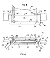
- each of rails 29, 30 is a pair of rails, for example pair 30, Fig. 6, to provide the supporting surface for gel plate assembly 40.
- the bottom of each rail features a supporting trough 32 with a front lip 34, that holds gel plate assembly 40 from falling off the rails-see also Figure 1.
- Trough 32 in turn comprises a vertical shoulder 36 and a bottom ledge 38.
- each rail includes a flange 39 that runs the length of the rail, as shown for rail 30 in Figs. 4 and 7, to cooperate with clamps for the buffer tanks, as described hereinafter, or with clamps for the gel plate assembly.
- Each of the pairs of rails 29 or 30 is associated with its own clam shell. As such, the device permits two electrophoresis gel plate assemblies to be run simultaneously. Alternatively, additional pairs (not shown) can be mounted from the same post, the support being rotated about post 24 until the desired gel plate assembly is facing the operator.
- the gel plate assembly supporting surfaces comprising the pair of rails is mounted to form an angle a, Figure 1, that is inclined from the vertical by an amount between about 5 and 100.
- Figure 1 that is inclined from the vertical by an amount between about 5 and 100.
- the bottom of the gel plate assembly and buffer tank 70 are closer to the operator, when the gel plate assembly faces the operator, than are the top of the gel plate assembly and buffer tank 100.
- the advantage is that, unlike perfectly vertical plate supports of conventional devices, no care is required to hold the plate on the support while clamps are mounted in place. Instead, the plate is simply inserted into troughs 32, and leaned back against rails 29 or 30. The troughs 32 are effective in preventing the plate from dropping lower, and angle a is effective in preventing plate 40 from tipping over, until buffer tanks 70 and 100 are installed.
- Angle a is preferably no less than 50, since otherwise the angle is insufficiently different from a vertical orientation, and tipping is more likely. It is preferably no greater than 100, since more than that tends to make the device too bulky at the bottom.
- Gel plate assembly 40 is the entire assembly shown, which comprises a front transparent plate 42, a rear transparent plate 44, both preferably made of glass, and spacers 46, 48 separating the two to allow gel (not shown) to be formed between them, as is conventional.
- rear plate 44 is improved to insure superior formation and observance of dye lines in electrophoresed samples. That is, plate 44 comprises a front surface 50 and a rear surface 52. Rear surface 52 is coated with a mirroring material 54, such as silver or aluminum, and a layer 56 is bonded over coating 54 substantially over the entire area in back of the flow surface area of plate assembly 40.
- the bonding of layer 56 over an area "in back of the flow surface area" of the gel plate assembly means, over an area having an extension that is coincident with, and behind, the flow surface area of the gel, wherein the electrophoresis lanes lie.
- This area is defined by length "I”, Figure 1, and width "w", Figure 3.
- Layer 56 is selected from a material that is effective in distributing or transferring heat, for example, aluminum.
- This layer is tightly bonded to coating 54 over substantially all of its surface, by using any suitable means, for example an adhesive such as an acrylic adhesive.
- the entire laminate so formed is then preferably overcoated with a non-conductive corrosion-resistant layer for protection.
- layer 56 is not used to dissipate heat from the gel plate assembly. Rather, the supporting surfaces formed by flanges 39 are deliberately held off from body 28 a distance effective to create a dead air space 58, Figures 4 and 8. This insulating air space insures that the heat generated by the process remains in place, thus reducing the time needed to achieve operating temperature.
- Layer 56 is thus effective to transfer heat from the hotter center regions, to the peripheral regions, thereby reducing temperature gradients.
- dye lines form in the gel that have the desired straightness, and the results are free of thermally induced artifacts.
- the overall temperature remains high, thus inducing the dye fronts to progress faster than is the case with water-backed units. That is, the water takes much longer to heat up to operating temperature.
- the ability of the dye fronts to be processed substantially free of artifacts remains even when supplying as much as 60 watts of power to achieve temperatures as high as 70 ° C, when measured at the front of plate 42, producing dye front speeds as high as 0.5 cm/min.
- a gel plate assembly is provided with the mirrored surface 54.
- This surface insures that the user can more readily tell the condition of surface 50, Figure 3. That is, the mirrored surface makes it easier to accurately introduce sample solution by pipette into the cavity between plates 42 and 44. It also helps reveal particles of dirt, if any, on surface 50 when plate 44 is being cleaned. The dye lines are also more easily detected with the mirror in place.
- the gel plate assembly can be clamped onto the electrophoresis device by any clamping means, including conventional ones. Most preferably, it is mounted by clamping means that not only clamp the gel plate assembly in position, but also clamp one or both buffer tanks to the support.
- such tank preferably comprises a cavity 74, Figures 6 and 7, open at top surface 76, Figure 5.
- the tank has manual grasping ears 78 at either end, and two clamps 80, 80' journalled on posts 82 to top surface 76.
- Each clamp has a handle portion 83.
- a torsion spring 84 is wrapped around each post 82 at one end, Figure 6, and secured at its other end to a screw 86 attached to surface 76.
- clamps 80 and 80' are biased to press inwardly-that is, clamp 80 is biased to rotate counterclockwise, Figure 6, and 80' to rotate clockwise.
- the effect is to not only clamp tank 70 to the support at rails 29, but preferably also to clamp gel plate assembly 40 between the buffer tank and the rails 29.
- Clamps 80 and 80' work by simply grasping the clamp with the thumb and one of the ears with the fingers, and pressing against the torsion spring to release the clamp from contact with the gel plate assembly. This in turn releases the buffer tank from engagement with rails 29 or 30, so that the buffer tank can be removed and cleaned.
- a banana plug 90 is mounted at the side of tank 70 for connection to power wires. Inside the tank, plug 90 connects with a wire electrode 92, Figure 5, that is supported by a rod or tube 94 that extends along the bottom of tank 70. Tube 94 and electrode 92 are preferably removable as a unit.
- the front face 96 of tank 70 can be transparent, to aid in viewing the contents thereof.
- tank 100 is releasably clamped to the other end of gel plate assembly 40, Figure 1. That is, its clamp, the details of which are not shown, preferably holds the upper end of the gel plate assembly against rails 29 and 30, by sandwiching the assembly between the rails and buffer tank 100.
- the frame by which device 20 rotates comprises, Figure 2, trapezoids 172 mounted vertically on two horizontal plates 174 and 176.
- Plate 174 is apertured at 178 to allow post 24 to freely extend through it.
- Plate 176 provides bushing 60, described hereafter.
- the outwardly facing edges 180, 182 of each trapezoid 172 provide the mounting support for the pairs of rails mounting on the clam shell bodies, shown in phantom.
- Bushing 60, Figure 2 rides on a point (not shown). In this fashion, the entire frame comprising plates 174, 176, bushing 60, trapezoids 172 and the attached clam shell bodies and rails, rotates on post 24.
- locking mechanism 170 temporarily prevents rotation of device 20 by the use of a two- position push latch, of a conventional construction, not shown, effective to cause a member to engage or disengage the teeth of a lock plate 186.
Landscapes
- Health & Medical Sciences (AREA)
- Life Sciences & Earth Sciences (AREA)
- Chemical & Material Sciences (AREA)
- Molecular Biology (AREA)
- Biochemistry (AREA)
- Immunology (AREA)
- Physics & Mathematics (AREA)
- Analytical Chemistry (AREA)
- Chemical Kinetics & Catalysis (AREA)
- General Health & Medical Sciences (AREA)
- General Physics & Mathematics (AREA)
- Electrochemistry (AREA)
- Pathology (AREA)
- Dispersion Chemistry (AREA)
- Peptides Or Proteins (AREA)
- Electrostatic Separation (AREA)
- Investigating, Analyzing Materials By Fluorescence Or Luminescence (AREA)
- Apparatus Associated With Microorganisms And Enzymes (AREA)
- Electrochromic Elements, Electrophoresis, Or Variable Reflection Or Absorption Elements (AREA)
Claims (2)
eine transparente Platte (44) mit einer Vorderfläche (50) und einer Rückfläche (52) sowie Mittel (42, 46, 48) aufweist, die ein Gel einschließen und über einen Strömungsflächenbereich mit der Vorderfläche (50) der Platte (44) in Kontakt halten,
dadurch gekennzeichnet, daß die Rückfläche (52) der Platte (44) mit einer Verspiegelung (54) versehen ist und daß
die Plattenanordnung (40, 42, 44, 46, 48, 50, 52, 54, 56) außerdem eine Temperatursteuereinrichtung (56) besitzt, die mit der Verspiegelung (54) in Berührung steht und für eine gleichmäßige Temperaturverteilung in dem Strömungsflächenbereich sorgt.
Applications Claiming Priority (2)
| Application Number | Priority Date | Filing Date | Title |
|---|---|---|---|
| US187668 | 1988-04-28 | ||
| US07/187,668 US4802969A (en) | 1988-04-28 | 1988-04-28 | Gel plate assembly for electrophoresis |
Publications (3)
| Publication Number | Publication Date |
|---|---|
| EP0339974A2 EP0339974A2 (de) | 1989-11-02 |
| EP0339974A3 EP0339974A3 (de) | 1991-08-28 |
| EP0339974B1 true EP0339974B1 (de) | 1993-08-04 |
Family
ID=22689946
Family Applications (1)
| Application Number | Title | Priority Date | Filing Date |
|---|---|---|---|
| EP89304164A Expired - Lifetime EP0339974B1 (de) | 1988-04-28 | 1989-04-26 | Plattenzusammensetzung für die Elektroforese |
Country Status (8)
| Country | Link |
|---|---|
| US (1) | US4802969A (de) |
| EP (1) | EP0339974B1 (de) |
| JP (1) | JPH0754853Y2 (de) |
| AU (1) | AU612826B2 (de) |
| CA (1) | CA1338173C (de) |
| DE (1) | DE68907990T2 (de) |
| DK (1) | DK170489B1 (de) |
| IL (1) | IL90118A (de) |
Families Citing this family (8)
| Publication number | Priority date | Publication date | Assignee | Title |
|---|---|---|---|---|
| US6004446A (en) * | 1984-03-29 | 1999-12-21 | Li-Cor, Inc. | DNA Sequencing |
| CA1341584C (en) * | 1988-04-06 | 2008-11-18 | Bruce Wallace | Method of amplifying and detecting nucleic acid sequences |
| CA1339832C (en) * | 1988-10-06 | 1998-04-21 | Philip A. Guadagno | Gel layer interface for electrophoresis chamber |
| US4975170A (en) * | 1990-03-29 | 1990-12-04 | Eastman Kodak Company | Back support for an electrophoresis gel plate assembly |
| US5112470A (en) * | 1990-12-07 | 1992-05-12 | Stratagene | Electrophoresis apparatus |
| US5543026A (en) * | 1994-02-07 | 1996-08-06 | The Perkin-Elmer Corporation | Real-time scanning fluorescence electrophoresis apparatus for the analysis of polynucleotide fragments |
| EP0684468A3 (de) * | 1994-05-27 | 1997-03-26 | Eastman Kodak Co | Kondensationsfreies Elektrophoresegerät. |
| US6379519B1 (en) * | 1999-09-01 | 2002-04-30 | Mirador Dna Design Inc. | Disposable thermoformed electrophoresis cassette |
Family Cites Families (7)
| Publication number | Priority date | Publication date | Assignee | Title |
|---|---|---|---|---|
| US3402118A (en) * | 1963-12-20 | 1968-09-17 | Camag Chemie | Apparatus for electrophoretic separation |
| US3994593A (en) * | 1974-10-07 | 1976-11-30 | Olympus Optical Co., Ltd. | Apparatus for automatic quantitative analysis of blood serum specimens by cataphoretic process |
| US3980540A (en) * | 1975-03-28 | 1976-09-14 | Hoefer Scientific Instruments | Vertical gel slab electrophoresis apparatus and method |
| JPS613045A (ja) * | 1984-06-18 | 1986-01-09 | Hitachi Ltd | 電気泳動装置 |
| JPS6113044A (ja) * | 1984-06-28 | 1986-01-21 | Masanobu Sakagami | フライホイ−ル |
| JPS62184343A (ja) * | 1986-02-07 | 1987-08-12 | Fuji Photo Film Co Ltd | 電気泳動装置 |
| JPS62220851A (ja) * | 1986-03-20 | 1987-09-29 | Fuji Photo Film Co Ltd | 電気泳動装置 |
-
1988
- 1988-04-28 US US07/187,668 patent/US4802969A/en not_active Expired - Fee Related
-
1989
- 1989-03-07 CA CA000592950A patent/CA1338173C/en not_active Expired - Fee Related
- 1989-04-25 JP JP1989048772U patent/JPH0754853Y2/ja not_active Expired - Lifetime
- 1989-04-26 EP EP89304164A patent/EP0339974B1/de not_active Expired - Lifetime
- 1989-04-26 AU AU33390/89A patent/AU612826B2/en not_active Ceased
- 1989-04-26 DE DE89304164T patent/DE68907990T2/de not_active Expired - Fee Related
- 1989-04-27 DK DK205089A patent/DK170489B1/da active
- 1989-04-28 IL IL90118A patent/IL90118A/xx not_active IP Right Cessation
Also Published As
| Publication number | Publication date |
|---|---|
| EP0339974A2 (de) | 1989-11-02 |
| AU3339089A (en) | 1989-11-02 |
| EP0339974A3 (de) | 1991-08-28 |
| DK205089D0 (da) | 1989-04-27 |
| IL90118A (en) | 1993-08-18 |
| DE68907990D1 (de) | 1993-09-09 |
| US4802969A (en) | 1989-02-07 |
| CA1338173C (en) | 1996-03-19 |
| DK170489B1 (da) | 1995-09-18 |
| AU612826B2 (en) | 1991-07-18 |
| JPH026254U (de) | 1990-01-16 |
| IL90118A0 (en) | 1989-12-15 |
| DK205089A (da) | 1989-10-29 |
| JPH0754853Y2 (ja) | 1995-12-18 |
| DE68907990T2 (de) | 1994-03-03 |
Similar Documents
| Publication | Publication Date | Title |
|---|---|---|
| EP0339974B1 (de) | Plattenzusammensetzung für die Elektroforese | |
| AU706048B2 (en) | Apparatus and method for electrophoresis | |
| DK0979146T3 (da) | Reaktionsbeholderapparat | |
| JPS62184343A (ja) | 電気泳動装置 | |
| GB2169703A (en) | Horizontal electroblotting | |
| US4828669A (en) | Electrophoresis device with removable buffer tank | |
| IT1205959B (it) | Urli elettrodi durevoli per elettrolisi e procedimento per prod | |
| IT1188636B (it) | Processo e apparecchio di pirolisi e di analisi di campioni contenenti materiale organico e cartuccia di stoccaggio e di riscaldamento di campioni utilizzabile nell'apparecchio che serve all'attuazione del processo | |
| EP0339975B1 (de) | Elektroforesevorrichtung mit fast senkrechten Gelplatten | |
| EP0339971B1 (de) | Elektroforesevorrichtung | |
| IT8219191A0 (it) | Tecnica elettroforetica perfezionata per separare isoenzimi di lattato deidrogenasi e gel elettroforetico perfezionato perl'impiego in essa. | |
| GB2114158A (en) | Electrode for use in cationic electrodeposition coating and coating method using the same | |
| JPS6370155A (ja) | 安全装置をそなえた電気泳動装置 | |
| CN223758407U (zh) | 一种温度均匀的发热装置 | |
| JP2004531705A (ja) | ゲル処理およびトランスファー装置 | |
| AU4122289A (en) | New electrolysis cell and electrolysis apparatus for its use | |
| IT8248840A0 (it) | Apparecchio elettrolitico con membrana scambiatrice di ioni e procedimento per produrlo | |
| JP2500120Y2 (ja) | スラブゲル電気泳動装置 | |
| JPH04232455A (ja) | 可変幅電気泳動装置 | |
| IT1282631B1 (it) | Tavolo di lavoro con sostegno braccia in particolare per laboratorio medico | |
| JPH0526137U (ja) | ゲルプレートアセンブリー装置用の改良された裏支持体 | |
| IT8219192A0 (it) | Tecnica elettroforetica migliorata per separare isoenzimi e gel elettroforetico migliorato perl'impiego in essa. | |
| Moskvitin et al. | The Effect of Cryolite Ratio on the Physical and Chemical Properties of the Electrolyte Used in Three-Layer Aluminum Refining | |
| GB9200778D0 (en) | Means of using electrical generating cell(s)in sub zero(celcius)temperatures | |
| IT9019523A1 (it) | Struttura di passerella, per il supporto ed il contenimento dei cavi elettrici di grossa e media sezione |
Legal Events
| Date | Code | Title | Description |
|---|---|---|---|
| PUAI | Public reference made under article 153(3) epc to a published international application that has entered the european phase |
Free format text: ORIGINAL CODE: 0009012 |
|
| AK | Designated contracting states |
Kind code of ref document: A2 Designated state(s): CH DE FR GB IT LI SE |
|
| PUAL | Search report despatched |
Free format text: ORIGINAL CODE: 0009013 |
|
| AK | Designated contracting states |
Kind code of ref document: A3 Designated state(s): CH DE FR GB IT LI SE |
|
| 17P | Request for examination filed |
Effective date: 19920206 |
|
| 17Q | First examination report despatched |
Effective date: 19920319 |
|
| GRAA | (expected) grant |
Free format text: ORIGINAL CODE: 0009210 |
|
| ITF | It: translation for a ep patent filed | ||
| AK | Designated contracting states |
Kind code of ref document: B1 Designated state(s): CH DE FR GB IT LI SE |
|
| REF | Corresponds to: |
Ref document number: 68907990 Country of ref document: DE Date of ref document: 19930909 |
|
| ET | Fr: translation filed | ||
| PLBE | No opposition filed within time limit |
Free format text: ORIGINAL CODE: 0009261 |
|
| STAA | Information on the status of an ep patent application or granted ep patent |
Free format text: STATUS: NO OPPOSITION FILED WITHIN TIME LIMIT |
|
| 26N | No opposition filed | ||
| EAL | Se: european patent in force in sweden |
Ref document number: 89304164.0 |
|
| PGFP | Annual fee paid to national office [announced via postgrant information from national office to epo] |
Ref country code: GB Payment date: 19980312 Year of fee payment: 10 |
|
| PGFP | Annual fee paid to national office [announced via postgrant information from national office to epo] |
Ref country code: SE Payment date: 19980407 Year of fee payment: 10 |
|
| PGFP | Annual fee paid to national office [announced via postgrant information from national office to epo] |
Ref country code: FR Payment date: 19980408 Year of fee payment: 10 |
|
| PGFP | Annual fee paid to national office [announced via postgrant information from national office to epo] |
Ref country code: DE Payment date: 19980429 Year of fee payment: 10 |
|
| PG25 | Lapsed in a contracting state [announced via postgrant information from national office to epo] |
Ref country code: GB Free format text: LAPSE BECAUSE OF NON-PAYMENT OF DUE FEES Effective date: 19990426 |
|
| PG25 | Lapsed in a contracting state [announced via postgrant information from national office to epo] |
Ref country code: SE Free format text: LAPSE BECAUSE OF NON-PAYMENT OF DUE FEES Effective date: 19990427 |
|
| PGFP | Annual fee paid to national office [announced via postgrant information from national office to epo] |
Ref country code: CH Payment date: 19991029 Year of fee payment: 11 |
|
| GBPC | Gb: european patent ceased through non-payment of renewal fee |
Effective date: 19990426 |
|
| PG25 | Lapsed in a contracting state [announced via postgrant information from national office to epo] |
Ref country code: FR Free format text: LAPSE BECAUSE OF NON-PAYMENT OF DUE FEES Effective date: 19991231 |
|
| EUG | Se: european patent has lapsed |
Ref document number: 89304164.0 |
|
| REG | Reference to a national code |
Ref country code: FR Ref legal event code: ST |
|
| PG25 | Lapsed in a contracting state [announced via postgrant information from national office to epo] |
Ref country code: DE Free format text: LAPSE BECAUSE OF NON-PAYMENT OF DUE FEES Effective date: 20000201 |
|
| PG25 | Lapsed in a contracting state [announced via postgrant information from national office to epo] |
Ref country code: LI Free format text: LAPSE BECAUSE OF NON-PAYMENT OF DUE FEES Effective date: 20000430 Ref country code: CH Free format text: LAPSE BECAUSE OF NON-PAYMENT OF DUE FEES Effective date: 20000430 |
|
| REG | Reference to a national code |
Ref country code: CH Ref legal event code: PL |
|
| PG25 | Lapsed in a contracting state [announced via postgrant information from national office to epo] |
Ref country code: IT Free format text: LAPSE BECAUSE OF NON-PAYMENT OF DUE FEES;WARNING: LAPSES OF ITALIAN PATENTS WITH EFFECTIVE DATE BEFORE 2007 MAY HAVE OCCURRED AT ANY TIME BEFORE 2007. THE CORRECT EFFECTIVE DATE MAY BE DIFFERENT FROM THE ONE RECORDED. Effective date: 20050426 |