EP0339936B1 - Appareil et procédé d'alimentation en feuilles - Google Patents
Appareil et procédé d'alimentation en feuilles Download PDFInfo
- Publication number
- EP0339936B1 EP0339936B1 EP89304110A EP89304110A EP0339936B1 EP 0339936 B1 EP0339936 B1 EP 0339936B1 EP 89304110 A EP89304110 A EP 89304110A EP 89304110 A EP89304110 A EP 89304110A EP 0339936 B1 EP0339936 B1 EP 0339936B1
- Authority
- EP
- European Patent Office
- Prior art keywords
- stripper
- sheets
- stacking
- transport
- rollers
- Prior art date
- Legal status (The legal status is an assumption and is not a legal conclusion. Google has not performed a legal analysis and makes no representation as to the accuracy of the status listed.)
- Expired - Lifetime
Links
Images


Classifications
-
- B—PERFORMING OPERATIONS; TRANSPORTING
- B65—CONVEYING; PACKING; STORING; HANDLING THIN OR FILAMENTARY MATERIAL
- B65H—HANDLING THIN OR FILAMENTARY MATERIAL, e.g. SHEETS, WEBS, CABLES
- B65H29/00—Delivering or advancing articles from machines; Advancing articles to or into piles
- B65H29/38—Delivering or advancing articles from machines; Advancing articles to or into piles by movable piling or advancing arms, frames, plates, or like members with which the articles are maintained in face contact
- B65H29/40—Members rotated about an axis perpendicular to direction of article movement, e.g. star-wheels formed by S-shaped members
-
- B—PERFORMING OPERATIONS; TRANSPORTING
- B65—CONVEYING; PACKING; STORING; HANDLING THIN OR FILAMENTARY MATERIAL
- B65H—HANDLING THIN OR FILAMENTARY MATERIAL, e.g. SHEETS, WEBS, CABLES
- B65H3/00—Separating articles from piles
- B65H3/02—Separating articles from piles using friction forces between articles and separator
- B65H3/06—Rollers or like rotary separators
- B65H3/063—Rollers or like rotary separators separating from the bottom of pile
-
- G—PHYSICS
- G07—CHECKING-DEVICES
- G07D—HANDLING OF COINS OR VALUABLE PAPERS, e.g. TESTING, SORTING BY DENOMINATIONS, COUNTING, DISPENSING, CHANGING OR DEPOSITING
- G07D11/00—Devices accepting coins; Devices accepting, dispensing, sorting or counting valuable papers
- G07D11/10—Mechanical details
- G07D11/16—Handling of valuable papers
- G07D11/165—Picking
-
- B—PERFORMING OPERATIONS; TRANSPORTING
- B65—CONVEYING; PACKING; STORING; HANDLING THIN OR FILAMENTARY MATERIAL
- B65H—HANDLING THIN OR FILAMENTARY MATERIAL, e.g. SHEETS, WEBS, CABLES
- B65H2301/00—Handling processes for sheets or webs
- B65H2301/40—Type of handling process
- B65H2301/42—Piling, depiling, handling piles
- B65H2301/421—Forming a pile
- B65H2301/4214—Forming a pile of articles on edge
- B65H2301/42146—Forming a pile of articles on edge by introducing articles from above
-
- B—PERFORMING OPERATIONS; TRANSPORTING
- B65—CONVEYING; PACKING; STORING; HANDLING THIN OR FILAMENTARY MATERIAL
- B65H—HANDLING THIN OR FILAMENTARY MATERIAL, e.g. SHEETS, WEBS, CABLES
- B65H2701/00—Handled material; Storage means
- B65H2701/10—Handled articles or webs
- B65H2701/19—Specific article or web
- B65H2701/1912—Banknotes, bills and cheques or the like
Definitions
- the invention relates to sheet feeding apparatus, for example sheet counting apparatus such as banknote counting apparatus.
- the invention also relates to methods for operating such apparatus.
- EP-A-0130825 we describe and illustrate sheet feeding apparatus in which stripper means rollers are mounted on a stripper shaft positioned about a transport shaft carrying one of each pair of sheet transport means rollers to allow the rollers of the sheet transport means and the stripper means to be separately driven by respective motors.
- the advantage of this is that when the apparatus is used for batch feeding and the like, the stripper means rollers can be stopped to prevent the feeding of further sheets to the sheet transport means but the sheet transport means rollers can continue to rotate to clear all previously fed sheets out of the apparatus. This ability is also useful when the passage of overlapped sheets and other misfeeds is detected.
- US-A-4474365 and WO-A-8402327 also describe a number of independantly driven rollers mounted about a common axis.
- sheet feeding apparatus for feeding sheets from a stack of sheets at an input store to a stacking position, comprises stripper means for drawing sheets out of the input store, the stripper means including at least one roller; transport means including at least one pair of rollers defining a nip into which single sheets are fed by the stripper means; rotatable stacking means at the stacking position to which sheets are delivered by the transport means; and drive means for driving the stripper means, transport means and stacking means whereby the stacking means is actuable to continue to stack sheets when the stripper and transport means are controlled to prevent further sheets being fed, characterized in that the at least one stripper means roller and one of each pair of transport means rollers are mounted non-rotatably to a common shaft, the arrangement being such that sheets are fed at substantially the same speed by the stripper rollers and the transport rollers.
- This apparatus simplifies the known sheet feeding apparatus by mounting the stripper means and one of each pair of transport means rollers to a common shaft. This reduces cost and complexity and hence reduces the risk of break-down as well as enabling a reduction in the overall size of the apparatus to be achieved.
- the apparatus further comprises sheet detection means operable to detect the passage of a sheet through the transport means nip by monitoring relative deflection of the rollers defining the nip.
- This sheet detection means may take the form described in EP-A-0130825.
- a method of operating such sheet feeding apparatus comprising monitoring the relative deflection of the transport means rollers before any sheets are fed by the stripper means and storing the monitored deflections to define a nip profile; and comparing subsequent deflections of the transport means rollers with corresponding parts of the stored profile.
- the profile may be updated at regular moments when no sheet is being fed through the nip.
- the sheet feeding apparatus When the sheet feeding apparatus is used to count batches of sheets (as opposed to a simple counting operation), it is necessary to prevent sheets from being withdrawn from the stack at the input store as soon as the required number has been withdrawn while allowing all the withdrawn sheets to be fed through the apparatus and be stacked at the stacking position. In our earlier apparatus, this is achieved by stopping the stripper means but allowing the transport means and stacking means to continue to rotate. In the present case, this is more difficult since stopping the stripper means will automatically cause the transport means also to stop.
- the second transmission comprises a drive belt coupled between the common drive means and the stacking means via a single direction freewheel clutch.
- the single direction freewheel clutch could couple a drive pulley with the common drive means or be provided to connect a shaft to which the stacking means is connected with a pulley about which the drive belt is entrained.
- the first transmission comprises a toothed drive belt connected between the drive means and the shaft to which the at least one stripper means roller and the one of each pair of transport means rollers are non-rotatably mounted.
- a plain 'O' ring could be used.
- the subsidiary transmission comprises a drive belt coupled between the shaft and the stacking means, the drive belt being adapted to slip when the stacking means is driven via the second transmission.
- the initial braking and halting of the whole mechanism prevents further sheets from being drawn from the store by the stripper means.
- common drive means is provided to drive the stripper means, transport means, and stacking means, the stacking means being mounted non-rotatably on a shaft coupled via a single direction free-wheel clutch to the common drive means, whereby the stacking means can continue to rotate after the stripper and transport means have stopped.
- the stripper and transport means rollers mounted to the shaft may be provided as separate roller members but conveniently are formed by a common cylindrical member which simplifies construction of this part of the apparatus.
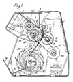
- the apparatus illustrated in the drawings is a banknote counting apparatus.
- the apparatus comprises two metal side plates 1 supporting a feed plate 2 and a face plate 3 of an input hopper 4.
- Three conventional picker wheels 5 are rotatably mounted to the side plates 1 and have radially outwardly projecting bosses 6 which, as the picker wheels rotate, periodically protrude through slots in the feed plate 2.
- a guide plate 7 having a curved guide surface 8 is pivotally mounted by an arm 7′ to a shaft 11 which is located via the face plate 3.
- Two separation rollers 10 (only one shown in the drawings) are mounted for rotation with the shaft 11 journalled via the face plate 3.
- Other separation means such as stationary shoes could also be used.
- a cantilevered arm 12 is connected to the guide plate 7 and includes a spring clip 13. When the guide plate 7 is in its first position shown, the spring clip 13 is located around a stationary shaft 14. If it is desired to cause the plate 7 to pivot away from its first position, the clip 13 is simply unclipped from the shaft 14 and pivoted in an anti-clockwise direction (as seen in Figure 1) allowing the operator access to the note feed path so that a note jam can be cleared.
- a pair of transport rollers 15 are non-rotatably mounted to a transport shaft 16 which is rotatably mounted to the side plates 1.
- Each transport roller 15 has an outer annular portion 17 of rubber.
- Each transport roller 15 contacts a respective auxiliary roller 18 rotatably mounted on the shaft 14.
- the transport rollers 15 (and auxiliary rollers 18) are axially spaced apart by a distance less than the width of sheets being counted.
- a pair of stripper rollers 19 having rubber inserts 19′ are non-rotatably mounted on the shaft 16.
- the stripper rollers 19 are positioned so as to define a small separation gap with the separation rollers 10 opposite which they are mounted. (A single wide stripper roller could be used in place of the rollers 19)
- the rollers 15, 19 have substantially the same outer diameter.
- a drive motor 30 drives the shaft 16 via a toothed drive belt 31 entrained about pulleys 20, 21 ( Figure 2).
- the picker wheels 5 are mounted non-rotatably on a shaft 23 which is driven from the shaft 16 via a toothed drive belt 32 entrained about pulleys 24, 25.
- a guide plate 34 extends from adjacent the nips formed between the rollers 15 and auxiliary rollers 18 to a pair of conventional stacker wheels 35 rotatably mounted between the side plates 1 on a shaft 38.
- the guide plate 34 together with an end plate 36 define an output hopper 37.
- a flywheel 44 is mounted non-rotatably to the shaft 38 while the shaft is driven from the shaft 16 via a crossed belt 45 entrained around a pulley 46, coupled with the shaft 16, and a pulley 47 coupled to the shaft 38 via a single direction free wheel clutch assembly 48, such as a Torrington clutch.
- FIG. 4 A modification of the apparatus shown in Figure 3 is illustrated in Figure 4 in which the shaft 38 is driven via a crossed belt 45′ and entrained around a pulley 46′ coupled with the shaft 23.
- rollers 15 and auxiliary rollers 18 define sheet sensing apparatus for detecting the passage of two or more notes simultaneously and for counting banknotes using the method described in EP-A-0130825 the disclosure of which is incorporated herein by reference.
- the shaft 14 is hollow, and is non-rotatably supported by the side plates 1, and carries the two auxiliary rollers 18. These are identical in construction and each contacts a respective one of the rollers 15.
- Each roller 18 comprises a roller bearing having an annular outer race 39, an annular inner race 40 and bearing balls 41 positioned between the inner and outer races.
- the bearing is mounted coaxially about the shaft 14 on an annular rubber portion 42.
- a pin (not shown) abuts the radially inner surface of the inner race 40 and extends through the rubber portion 42 and an aperture in the shaft 14 into the shaft.
- Two light emitter/sensor pairs (not shown) are mounted in the shaft 14 on each side of respective pins so as to monitor radial movement of the pins.
- the output signals from the sensors are digitised and fed to a microprocessor 43 which processes them in the manner to be described.
- the basic mode of operation is as follows. A stack of banknotes is placed in the hopper 4 and the drive motor 30 activated. Rotation of the drive motor so as to cause the rollers 15, 19 to rotate in a feed forward direction as indicated by an arrow 49 in Figure 3 will also cause rotation of the shaft 38 carrying the stacking wheels 35 due to engagement of the clutch assembly 48. After suitable rotation of the rollers 15, 19 has taken place for the purpose to be described below, the projecting bosses 6 of the picker wheels 5 will engage the lowermost note in the stack and nudge this forward into the separation gaps between the rollers 19 and separation rollers 10. Rotation of the rollers 19 will bring the rubber portions 19′ into contact with a surface of the fed sheet to carry that sheet alongside the guide 7 into the nips between the rollers 15 and 18.
- rollers 15, 19 have substantially the same diameter and they are all mounted non-rotatably on the same shaft 16, the note will be fed at substantially the same speed by both sets of rollers. After passing through the nips, the note will pass into slots of the stacking wheels 35 which will rotate in an anti-clockwise direction, as seen in Figure 1, so that the notes will be stripped from the slots by plate 34 and be stacked in the hopper 37.
- the rollers 15, 18 undergo at least one full rotation.
- This rotation is monitored via a timing disc 60 ( Figure 1) mounted for rotation with the shaft 16 (or alternatively shaft 23) and primary and secondary light sensor/emitter pairs 61, 62 ( Figure 3).
- the timing disc 60 has forty equally spaced slots extending around its circumference.
- the output signals generated by the sensors of the pairs 61, 62 are fed to conventional digitising means (such as analogue/digital converters) and the digitised signals are then fed to the processor 43.
- the processor 43 responds to the signals from the two detection system sensors previously described (related to the deflection of the rollers 18) and stores the values of those output signals each time the primary sensor/emitter pair 61 detects the passage of a slot.
- the sampled values from the detection system are stored so as to constitute a profile of each nip.
- the output signals from the detection system will change since the pins will be depressed further into the shaft 14. This will cause changes in the output signals from the detection system which can then be compared with the stored profiles by resampling the output signals at exactly the same angular positions as the original signals were sampled to generate the profile.
- the profile of the nips can be updated at any convenient time when no note is present in the nips. Typically, the profile will be updated at times when no notes are present in the input hopper 4 so that the roller system can be safely rotated without the risk of drawing a new note into the nips. In addition, the profile could be reviewed during the passage of a batch of notes whenever no note is present in the nips. Since the timing disc 60 provides an accurate indication at all times of the positions of the rollers 15 relative to the nips, it is always possible for the processor 43 to determine whether the profile at that position should be updated.
- This exact position of the rollers 15 at the nips could be monitored by monitoring the sensor outputs from the sensor of the primary pair 61 to obtain the magnitude of any rotation of movement whilst detecting the polarity of back emf from the permanent magnet of the drive motor 30 to obtain direction of rotation.
- the secondary sensor/emitter pair 62 is provided so that transitions from an obscured state to a clear state for one of the sensor/emitter pairs occurs midway between similar transitions for the other sensor/emitter pair.
- the signals from the two sensors thus provide an unambiguous truth table which indicates the direction of any movement of the timing disc 60.
- a note may be positioned within the nips. Since the rollers 15 are stopped at the same time as the drive motor 30, the note will remain in the nips.
- the counting process may continue since the exact position of the rollers 15 is continuously monitored by the processor 43 by way of the timing disc 60 enabling data already deduced for the first part of the note to be used together with data for the second part of the note which will be detected on restart. If the note remaining in the nip is the last note and it has gone in sufficiently for a feed hopper sensor to clear then an error indication will be signalled on a display. This ensures the note is not left in the machine and forgotten. Once again, the exact position of the rollers 15 will be continuously monitored via the disc 60 when the note is pulled out.
- the apparatus shown in Figures 1 to 4 can be used for a variety of purposes including the batching of notes so as to generate a series of batches of a known number of notes or in a straightforward counting mode to count the total number of notes positioned in the input hopper 4.
- the motor 30 will need to be stopped at the end of each batch. As soon as the motor 30 is stopped, rotation of the shaft 16 and the shaft 23 will also stop thus preventing further notes from being fed out of the input hopper 4.
- the stripper and transport rollers 15, 19 are rapidly accelerated during an initial phase 51 to a terminal velocity of about 1400 rpm. This velocity is maintained during a phase 52 during which a majority of the batch of sheets is fed from the input hopper 4 to the output hopper 37.
- the drive motor 30 is decelerated during a phase 53 to an intermediate speed of for example 500 rpm and then is rapidly braked during a final braking phase 54.
- the stripper rollers 19 can be stopped between the time that the last sheet in the batch leaves the transport rollers 15 and the time at which the next sheet in the input hopper 4 is picked up.
- the stacker wheels 35 will continue to rotate under the influence of the flywheel 44 for a sufficiently long time to enable all remaining sheets held by the stacker wheels 35 to be stacked in the output hopper 37.
- the exact choice of durations for the phases 53, 54 and of the intermediate speed are determined empirically.
- This arrangement is similar to that shown in Figure 3 except that the pulley 47 is directly connected to the stacker wheel shaft 38 instead of via a Torrington clutch.
- the drive belt 31 and pulleys 20, 21 constitute a first transmission while the belt 45 constitutes a subsidiary transmission for driving the stacker wheel shaft 38 from the transport/stripper shaft 16.
- a second transmission is provided constituted by a drive belt 160 entrained around pulleys 161, 162 coupled with the stacker wheel shaft 38 and the drive motor 30 respectively.
- the pulley 161 is coupled to the shaft 38 via a Torrington clutch 63.
- the drive motor 30 causes rotation in the direction of the arrow 64 and corresponding rotation of the shafts 16, 38 so that sheets will be stacked in the manner described above. During this rotation, no drive is imparted to the pulley 47 by virtue of the clutch 63.
- the drive motor 30 Upon detection of the passage of the Xth sheet towards the end of a batch, for example the 95th sheet out of a batch of 100, the drive motor 30 is caused to slow down as described earlier (phase 53, Figure 6) and then as the last note leaves the transport nip the brake is applied which halts the feed, transport and stacker shafts. During this decleration and braking period the optimum stacker/note speed relationship is maintained as the stacker is directly driven from the transport via belt 45.
- the motor is instantly reversed for a short time eg 60° of one rotation in the direction of arrow 65.
- This reverse movement is coupled to the drive belt 160 as well as to the toothed drive belt 31.
- the reverse movement will cause a small angular reverse rotation of the rollers 15, 19 which in the absence of the drive belt 160 would cause reverse movement of the stacker wheels 35.
- connection between the drive belt 160 and the pulley 161 is designed to override the connection between the drive belt 45 and the pulley 47 so that in its simplest form for example the drive belt 45 slips whilst the drive belt 160 acts to rotate the shaft 38.
- the drive belt 45 slips whilst the drive belt 160 acts to rotate the shaft 38.
- reverse rotation of the motor 30 will cause the stacker shaft 38 to continue to rotate in the same, stacking direction. This reverse movement is continued for such a time as to ensure all sheets in the batch have been stacked.
- no sheets will be withdrawn from the input hopper 4 due to the reverse movement of the stripper rollers 19.
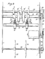
- stripper rollers 19 and transport rollers 15 have been shown as separate rollers mounted on a shaft 16.
- a modified form of this arrangement is shown in Figure 7 in which the stripper and transport rollers have been formed from a common member 66 having two axially inner circumferential portions 67 defining the stripper rollers (each having a rubber insert 68) and two axially outer, cylindrical portions 69 defining respective transport rollers.
- FIG. 10 Another example is shown in Figure 10.
- the transport motor 30 is coupled via a toothed belt 100 with a pulley 101 non-rotatably mounted on the transport and stripper shaft 102.
- the transport and stripper assembly is shown schematically at 103.
- a crossed belt 104 couples the shaft 102 with a pulley 105 mounted via a one-way clutch 106 to the stacker shaft 107.
- Stacking wheels 108 are shown schematically non-rotatably mounted to the shaft 107.
- the shaft 107 carries a second pulley 109 coupled via a one-way clutch (not shown) to the shaft and driven via a belt 110 from an auxiliary motor 111.
- the stacker shaft 107 is driven from the transport drive motor 20 via belts 104 and 100 with the auxiliary motor 111 switched off, the clutch system allowing the auxiliary motor belt 110 to remain stationary.
- the transport is stopped in the same manner as described above, at which point the auxiliary motor 111 is switched on.
- the auxiliary motor 111 now drives the stacker shaft 107 via the pulley 109 and its associated clutch, the clutch 106 allowing the belt 100 to remain stationary. After a predetermined length of time the auxiliary motor 111 is switched off. In this way, the final sheets fed by the transport system are stacked.
- the clutch system is such that the faster of the two drives, preferably the transport drive motor 20, will drive the stacker wheels 108, the other system idling.
- Figure 11 illustrates a modification of the Figure 10 example in which instead of the auxiliary motor 111, a solenoid 112 is provided connected to the shaft 107 via a double linkage 113 and a one-way clutch 114. In addition, a flywheel 115 is non-rotatably mounted to the stacker shaft 107.
- the stacker shaft 107 is driven from the transport drive motor 20 via belts 100 and 104 with the one-way clutch 114 free wheeling.
- the transport is stopped as before.
- the flywheel/clutch arrangement associated with the stacker shaft 107 ensures that the stacker shaft continues to rotate for a short period.
- the solenoid 112 is activated giving the shaft and flywheel a "kick" in the form of a short impulsive, rotational force which prolongs this run-on period to ensure that all notes are stacked correctly.
Landscapes
- Physics & Mathematics (AREA)
- General Physics & Mathematics (AREA)
- Engineering & Computer Science (AREA)
- Mechanical Engineering (AREA)
- Sheets, Magazines, And Separation Thereof (AREA)
- Pile Receivers (AREA)
- Discharge By Other Means (AREA)
Claims (13)
- Appareil d'amenée de feuilles amenant les feuilles à partir d'un empilage de feuilles au poste d'amenée (4) en position d'empilage (37), l'appareil comportant des moyens de dépouille (19) pour prélever les feuilles du poste d'amenée (4), les moyens de dépouille comportant un rouleau au minimum; des moyens de transport dont une paire de rouleaux (15,18) au minimum définissant un pincement auquel les feuilles simples sont amenées par les moyens de dépouille; et des moyens pivotante d'empilage (35) en position d'empilage (37) à laquelle les feuilles sont livrées par les moyens de transport; et des moyens de commande (15,18) entraînant les moyens de dépouille (19), moyens de transport (15,18) et moyens d'empilage (35), ces moyens d'empilage étant exploités pour continuer l'empilage des feuilles lorsque les moyens de dépouille et de transport sont commandés pour éviter une amenée supplémentaire de feuilles, caractérisé en ce que, le rouleau de dépouille (19) au minimum et l'un (15) de la paire de rouleaux de transport sont montés fixes sur un axe commun (16), l'agencement étant tel que les feuilles soient amenées essentiellement à la même vitesse par les rouleaux de dépouille et les rouleaux de transport.
- Appareil selon la revendication 1, dont les moyens commun de commande (30) sont prévus reliés par une première transmission (31) aux moyens de dépouille et de transport, la rotation des moyens d'empilage (35) étant effectuée par l'intermédiaire d'une transmission secondaire (45) entre les moyens d'empilage et les moyens de dépouille et de transport, les moyens de commande étant également reliés aux moyens d'empilage par une deuxième transmission à fonctionnement sélectif (60) provoquant à l'inversion des moyens de commande la rotation des moyens d'empilage de manière à empiler les feuilles, l'agencement étant tel qu'au démarrage de la deuxième transmission toute commande reliée aux moyens d'empilage par l'intermédiaire de la transmission première et secondaire cède la priorité.
- Appareil selon la revendication 2, dont la deuxième transmission comporte une courroie d'entraînement (60) accouplée entre les moyens de commande commune (30) et les moyens d'empilage par l'intermédiaire d'un embrayage unique unidirectionnel à roue libre (63).
- Appareil selon la revendication 2 ou la revendication 3, dont la première transmission comporte une courroie d'entraînement dentée (31) raccordant les moyens de commande (30) et l'axe (16) auquel le rouleau simple des moyens de dépouille et l'un de la paire de rouleaux de transport est monté fixe non-pivotant.
- Appareil selon la revendication 4, dont la transmission secondaire comporte une courroie de commande raccordant l'axe et les moyens d'empilage, la courroie de commande étant agencée de manière à glisser lorsque les moyens d'empilage sont commandés par l'intermédiaire de la deuxième transmission.
- Appareil selon la revendication 1, dont les moyens de commande commune (30) prévoient la commande des moyens de dépouille, les moyens de transport (103) et les moyens d'empilage (108), lesdits moyens d'empilage étant montés non-pivotants sur un axe (107) accouplé par l'intermédiaire d'un embrayage unique unidirectionnel à roue libre (106) aux moyens de commande commune (30), dont les moyens d'empilage peuvent continuer la rotation après l'immobilisation des moyens de dépouille et de transport.
- Appareil selon la revendication 6, comportant également une commande auxiliaire (111) accouplée à l'axe des moyens d'empilage (107), la commande auxiliaire étant actionnée lorsque les moyens de dépouille et de transport sont commandés de manière à condamner toute autre amenée de feuilles assurant l'empilage par les moyens d'empilage pour un délai prédéterminé.
- Appareil selon la revendication 6, comportant également un actionneur d'axe (112) accouplé à l'axe (107) des moyens d'empilage et fonctionnant pour assurer une impulsion de rotation à l'axe des moyens d'empilage lorsque les moyens de dépouille et de transport sont commandés pour condammer toute autre amenée de feuilles.
- Appareil selon l'une ou l'autre des revendications précédentes, dont les moyens d'empilage prévoient une roue pivotante d'empilage (35) ayant une série de fentes radiales de réception de feuilles ouvrant vers l'extérieur.
- Appareil selon l'une ou l'autre des revendications précédentes, prévoyant également des moyens de détection de feuille (43) exploitable pour la détection du passage de la feuille par le pincement des moyens de transport suite à la surveillance de la déflexion relative des rouleaux formant le pincement.
- Méthode d'exploitation d'un appareil d'amenée de feuille selon la revendication 10, la méthode comportant la surveillance de la déflexion relative des rouleaux de moyens de transport (15,18) avant l'amenée des feuilles par les moyens de dépouille (19) et la mise en mémoire des déflexions ainsi relevées pour définir un profil de pincement; et la comparaison de déflexions successives des rouleaux de moyens de transport (15,18) avec les éléments correspondants du profil en mémoire.
- Méthode d'exploitation d'un appareil d'amenée de feuille selon l'une ou l'autre des revendications 1 à 5, ou la revendication 9 ou la revendication 10 sous réserve d'une ou l'autre des revendications 1 à 5, de façon à former un empilage de N feuilles, la méthode comportant l'exploitation des moyens de dépouille et de transport et les moyens d'empilage à une première vitesse; le décompte des feuilles prélevées au poste d'amenée (4) et après avoir compté un nombre prédéterminé de feuilles X, lorsque N > X ont été comptées, provoquant la transition de l'exploitation des moyens de dépouille (19) et des moyens de transport (15,18) et des moyens d'empilage en une deuxième vitesse plus faible; et après avoir prélevé la n-ème feuille du poste d'amenée et l'avoir sortie du pincement de freinage des moyens de transport et immobilisé les moyens de dépouille, de transport et d'empilage et avoir inversé les moyens de commande de telle manière que les deuxièmes commandes de transmission entraînent les moyens d'empilage pour terminer l'empilage.
- Méthode d'exploitation d'un appareil d'amenée de feuille au minimum selon la revendication 6, de façon à former un empilage de N feuilles, la méthode comportant l'exploitation des moyens de dépouille et de transport et les moyens d'empilage à une première vitesse; le décompte des feuilles prélevées au poste d'amenée (4) et après avoir compté un nombre prédéterminé de feuilles 1, lorsque N > X ont été comptées, provoquant la transition de l'exploitation des moyens de dépouille (19) et des moyens de transport (15,18) et des moyens d'empilage en une deuxième vitesse plus faible; et après avoir prélevé la n-ème feuille du poste d'amenée le freinage des moyens de dépouille et de transport pour condamner tout autre prélèvement de feuilles du poste, les moyens d'empilage continuant leur rotation de façon à empiler les feuilles déjà sorties du poste d'amenée.
Applications Claiming Priority (2)
| Application Number | Priority Date | Filing Date | Title |
|---|---|---|---|
| GB888810244A GB8810244D0 (en) | 1988-04-29 | 1988-04-29 | Sheet feeding apparatus & method |
| GB8810244 | 1988-04-29 |
Publications (2)
| Publication Number | Publication Date |
|---|---|
| EP0339936A1 EP0339936A1 (fr) | 1989-11-02 |
| EP0339936B1 true EP0339936B1 (fr) | 1993-03-03 |
Family
ID=10636146
Family Applications (1)
| Application Number | Title | Priority Date | Filing Date |
|---|---|---|---|
| EP89304110A Expired - Lifetime EP0339936B1 (fr) | 1988-04-29 | 1989-04-25 | Appareil et procédé d'alimentation en feuilles |
Country Status (5)
| Country | Link |
|---|---|
| US (1) | US4968015A (fr) |
| EP (1) | EP0339936B1 (fr) |
| JP (1) | JPH0256330A (fr) |
| DE (1) | DE68905062D1 (fr) |
| GB (1) | GB8810244D0 (fr) |
Families Citing this family (12)
| Publication number | Priority date | Publication date | Assignee | Title |
|---|---|---|---|---|
| US5097273A (en) * | 1989-09-04 | 1992-03-17 | Minolta Camera Kabushiki Kaisha | Recording medium detecting apparatus |
| US5359929A (en) * | 1993-08-25 | 1994-11-01 | Rockwell International Corporation | Device for delivering signatures in a printing press |
| ES2133122B1 (es) * | 1996-11-28 | 2000-04-01 | Sallen Rosello Jaime | Adicion a la patente principal n. p9602515 por: sistema automatico manipulador de billetes. |
| ES2117587B1 (es) * | 1996-11-28 | 1999-04-16 | Sallen Rosello Jaime | Sistema automatico manipulador de billetes. |
| USD419183S (en) * | 1998-03-16 | 2000-01-18 | Stouffer Industries, Inc. | Locking hub |
| DE10008136A1 (de) * | 2000-02-22 | 2001-08-23 | Giesecke & Devrient Gmbh | Stapler für blattförmige Gegenstände |
| WO2005118443A2 (fr) * | 2004-06-04 | 2005-12-15 | De La Rue International Limited | Trieuse de documents |
| SE528000C2 (sv) * | 2004-12-22 | 2006-08-01 | Axlon Int Ab | Separeringsenhet för arkformiga värdedokument |
| US20060151941A1 (en) * | 2005-01-12 | 2006-07-13 | Pitney Bowes Limited | Speed control for sheet handling apparatus |
| US8733751B2 (en) * | 2011-04-13 | 2014-05-27 | Nisca Corporation | Sheet stacking device and sheet folding device |
| CN104183051A (zh) * | 2013-05-28 | 2014-12-03 | 李秋菊 | 新型单轴全红外验钞机 |
| JP2017173863A (ja) * | 2016-03-18 | 2017-09-28 | グローリー株式会社 | 貨幣処理装置および貨幣処理方法 |
Family Cites Families (14)
| Publication number | Priority date | Publication date | Assignee | Title |
|---|---|---|---|---|
| US2116613A (en) * | 1936-03-24 | 1938-05-10 | Bedford Robert Hardy | Gravity electrostatic separation process |
| US2294086A (en) * | 1938-07-08 | 1942-08-25 | Mcconnel Hinds Ltd | Pneumatic separating apparatus |
| US2310894A (en) * | 1941-01-22 | 1943-02-09 | Brusset Jean Albert | Dry flotation, and media and apparatus therefor |
| GB1152611A (en) * | 1966-09-13 | 1969-05-21 | Head Wrightson & Co Ltd | Improvements in or relating to Fluidised-Bed Apparatus |
| US3642271A (en) * | 1970-05-27 | 1972-02-15 | Bridge Data Products Inc | Card feeder |
| US4105199A (en) * | 1975-12-22 | 1978-08-08 | Nippon Electric Co., Ltd. | Paper feeder comprising a selectively drivable resilient body in frictional contact with a feed roller |
| US4279740A (en) * | 1979-02-19 | 1981-07-21 | Marusho Industrial Co., Ltd. | Light-material segregating method and apparatus |
| JPS57138847U (fr) * | 1981-02-24 | 1982-08-30 | ||
| US4474365A (en) * | 1981-07-30 | 1984-10-02 | Brandt, Inc. | Document feeding, handling and counting apparatus |
| US4451357A (en) * | 1982-05-17 | 1984-05-29 | Lavigne Gordon | Apparatus for dry placer mining and method of operating same |
| US4615518A (en) * | 1982-12-14 | 1986-10-07 | Brandt, Incorporated | Document handling and counting apparatus |
| US4650991A (en) * | 1983-07-01 | 1987-03-17 | De La Rue Systems Limited | Method and apparatus for sensing sheets |
| GB8319972D0 (en) * | 1983-07-25 | 1983-08-24 | De La Rue Syst | Sheet feeding apparatus |
| US4796878A (en) * | 1985-11-08 | 1989-01-10 | Brandt, Incorporated | Document handling counting apparatus |
-
1988
- 1988-04-29 GB GB888810244A patent/GB8810244D0/en active Pending
-
1989
- 1989-04-25 DE DE8989304110T patent/DE68905062D1/de not_active Expired - Lifetime
- 1989-04-25 EP EP89304110A patent/EP0339936B1/fr not_active Expired - Lifetime
- 1989-04-28 JP JP1107938A patent/JPH0256330A/ja active Pending
- 1989-04-28 US US07/345,216 patent/US4968015A/en not_active Expired - Fee Related
Also Published As
| Publication number | Publication date |
|---|---|
| EP0339936A1 (fr) | 1989-11-02 |
| JPH0256330A (ja) | 1990-02-26 |
| DE68905062D1 (de) | 1993-04-08 |
| US4968015A (en) | 1990-11-06 |
| GB8810244D0 (en) | 1988-06-02 |
Similar Documents
| Publication | Publication Date | Title |
|---|---|---|
| EP0339936B1 (fr) | Appareil et procédé d'alimentation en feuilles | |
| CN1315708C (zh) | 纸张分离和传送设备 | |
| US4470590A (en) | Stacking device for paper sheets | |
| JP2562981B2 (ja) | シート繰り出し装置 | |
| AU706031B2 (en) | Sheet feeding apparatus and method | |
| AU694660B2 (en) | Improvements relating to sheet feeding | |
| GB2094766A (en) | Stacking mechanism for paper notes | |
| JPH0739291B2 (ja) | 紙葉類分離繰出装置 | |
| US5769408A (en) | Apparatus for feeding sheets | |
| SE455896B (sv) | Anordning for separation av ark och framforing av arken ett och ett pa avstand fran varandra for underlettande av noggrann rekning av arken | |
| EP0260015B1 (fr) | Appareil d'alimentation en feuille | |
| US4482057A (en) | Record media dispensing apparatus | |
| EP0611034B1 (fr) | Système de comptage de feuilles | |
| EP0611718B1 (fr) | Dispositif pour empiler des feuilles | |
| JPH10338367A (ja) | シート送り装置 | |
| JP3968399B2 (ja) | 紙葉送り出し装置 | |
| GB2301092A (en) | Sheet transfer system | |
| JPH03259830A (ja) | 紙葉類取扱い装置 | |
| JPH0221038B2 (fr) | ||
| JPS61111245A (ja) | 紙葉類繰出装置 | |
| JP2573280B2 (ja) | 紙葉類の重送検出器 | |
| JPH03162332A (ja) | 紙葉類分離装置 | |
| EP0486252B1 (fr) | Mécanisme de limitation du moment de rotation, en usage dans un système d'entraînement | |
| SE522324C2 (sv) | Anordning för styckevis utmatning av dokument från en bunt av dokument | |
| JP2573691B2 (ja) | 紙葉類分離繰り出し装置 |
Legal Events
| Date | Code | Title | Description |
|---|---|---|---|
| PUAI | Public reference made under article 153(3) epc to a published international application that has entered the european phase |
Free format text: ORIGINAL CODE: 0009012 |
|
| AK | Designated contracting states |
Kind code of ref document: A1 Designated state(s): DE ES FR GB IT SE |
|
| 17P | Request for examination filed |
Effective date: 19900315 |
|
| 17Q | First examination report despatched |
Effective date: 19910722 |
|
| RAP1 | Party data changed (applicant data changed or rights of an application transferred) |
Owner name: DE LA RUE SYSTEMS LIMITED |
|
| GRAA | (expected) grant |
Free format text: ORIGINAL CODE: 0009210 |
|
| AK | Designated contracting states |
Kind code of ref document: B1 Designated state(s): DE ES FR GB IT SE |
|
| PG25 | Lapsed in a contracting state [announced via postgrant information from national office to epo] |
Ref country code: IT Free format text: LAPSE BECAUSE OF FAILURE TO SUBMIT A TRANSLATION OF THE DESCRIPTION OR TO PAY THE FEE WITHIN THE PRE;WARNING: LAPSES OF ITALIAN PATENTS WITH EFFECTIVE DATE BEFORE 2007 MAY HAVE OCCURRED AT ANY TIME BEFORE 2007. THE CORRECT EFFECTIVE DATE MAY BE DIFFERENT FROM THE ONE RECORDED.SCRIBED TIME-LIMIT Effective date: 19930303 Ref country code: ES Free format text: THE PATENT HAS BEEN ANNULLED BY A DECISION OF A NATIONAL AUTHORITY Effective date: 19930303 Ref country code: SE Effective date: 19930303 Ref country code: DE Effective date: 19930303 Ref country code: FR Effective date: 19930303 |
|
| REF | Corresponds to: |
Ref document number: 68905062 Country of ref document: DE Date of ref document: 19930408 |
|
| PGFP | Annual fee paid to national office [announced via postgrant information from national office to epo] |
Ref country code: GB Payment date: 19930419 Year of fee payment: 5 |
|
| EN | Fr: translation not filed | ||
| PLBE | No opposition filed within time limit |
Free format text: ORIGINAL CODE: 0009261 |
|
| STAA | Information on the status of an ep patent application or granted ep patent |
Free format text: STATUS: NO OPPOSITION FILED WITHIN TIME LIMIT |
|
| 26N | No opposition filed | ||
| PG25 | Lapsed in a contracting state [announced via postgrant information from national office to epo] |
Ref country code: GB Effective date: 19940425 |
|
| GBPC | Gb: european patent ceased through non-payment of renewal fee |
Effective date: 19940425 |