EP0339837B1 - Elektromagnetisches Ventil - Google Patents
Elektromagnetisches Ventil Download PDFInfo
- Publication number
- EP0339837B1 EP0339837B1 EP19890303666 EP89303666A EP0339837B1 EP 0339837 B1 EP0339837 B1 EP 0339837B1 EP 19890303666 EP19890303666 EP 19890303666 EP 89303666 A EP89303666 A EP 89303666A EP 0339837 B1 EP0339837 B1 EP 0339837B1
- Authority
- EP
- European Patent Office
- Prior art keywords
- passage
- molten metal
- frequency
- coil
- discharge
- Prior art date
- Legal status (The legal status is an assumption and is not a legal conclusion. Google has not performed a legal analysis and makes no representation as to the accuracy of the status listed.)
- Expired - Lifetime
Links
Images

Classifications
-
- B—PERFORMING OPERATIONS; TRANSPORTING
- B22—CASTING; POWDER METALLURGY
- B22D—CASTING OF METALS; CASTING OF OTHER SUBSTANCES BY THE SAME PROCESSES OR DEVICES
- B22D39/00—Equipment for supplying molten metal in rations
- B22D39/003—Equipment for supplying molten metal in rations using electromagnetic field
-
- Y—GENERAL TAGGING OF NEW TECHNOLOGICAL DEVELOPMENTS; GENERAL TAGGING OF CROSS-SECTIONAL TECHNOLOGIES SPANNING OVER SEVERAL SECTIONS OF THE IPC; TECHNICAL SUBJECTS COVERED BY FORMER USPC CROSS-REFERENCE ART COLLECTIONS [XRACs] AND DIGESTS
- Y10—TECHNICAL SUBJECTS COVERED BY FORMER USPC
- Y10T—TECHNICAL SUBJECTS COVERED BY FORMER US CLASSIFICATION
- Y10T137/00—Fluid handling
- Y10T137/206—Flow affected by fluid contact, energy field or coanda effect [e.g., pure fluid device or system]
- Y10T137/2082—Utilizing particular fluid
-
- Y—GENERAL TAGGING OF NEW TECHNOLOGICAL DEVELOPMENTS; GENERAL TAGGING OF CROSS-SECTIONAL TECHNOLOGIES SPANNING OVER SEVERAL SECTIONS OF THE IPC; TECHNICAL SUBJECTS COVERED BY FORMER USPC CROSS-REFERENCE ART COLLECTIONS [XRACs] AND DIGESTS
- Y10—TECHNICAL SUBJECTS COVERED BY FORMER USPC
- Y10T—TECHNICAL SUBJECTS COVERED BY FORMER US CLASSIFICATION
- Y10T137/00—Fluid handling
- Y10T137/206—Flow affected by fluid contact, energy field or coanda effect [e.g., pure fluid device or system]
- Y10T137/2087—Means to cause rotational flow of fluid [e.g., vortex generator]
- Y10T137/2104—Vortex generator in interaction chamber of device
-
- Y—GENERAL TAGGING OF NEW TECHNOLOGICAL DEVELOPMENTS; GENERAL TAGGING OF CROSS-SECTIONAL TECHNOLOGIES SPANNING OVER SEVERAL SECTIONS OF THE IPC; TECHNICAL SUBJECTS COVERED BY FORMER USPC CROSS-REFERENCE ART COLLECTIONS [XRACs] AND DIGESTS
- Y10—TECHNICAL SUBJECTS COVERED BY FORMER USPC
- Y10T—TECHNICAL SUBJECTS COVERED BY FORMER US CLASSIFICATION
- Y10T137/00—Fluid handling
- Y10T137/206—Flow affected by fluid contact, energy field or coanda effect [e.g., pure fluid device or system]
- Y10T137/218—Means to regulate or vary operation of device
- Y10T137/2191—By non-fluid energy field affecting input [e.g., transducer]
Definitions
- This invention relates to an electromagnetic valve, and particularly to an electromagnetic valve for use for discharge of molten metal from a container according to the preamble of claim 1.
- a method of controlling or preventing discharge of molten metal from a container through a discharge passage in the container below the level of the molten metal therein which comprises utilizing electromagnetic forces induced in the molten metal by an induction coil disposed around the container to move the molten metal away from the discharge passage in the container.
- an induction coil disposed around the container to move the molten metal away from the discharge passage in the container.
- a valve comprising a body providing a discharge passage through which, in use, molten metal will flow from a container under the action of gravity; an electrical induction coil located about the passage; and means to supply a high frequency electric current to the coil whereby the coil provides an alternating magnetic field which induces electric currents in molten metal in the passage, interaction between the field and the currents providing a force which urges the molten metal away from the wall of the passage towards the axis thereof.
- An electromagnetic overpressure is thus created in the molten metal in the passage, which overpressure can be used to regulate the flow of the molten metal from the container.
- the frequency f of the electric current supplied to the coil must be sufficiently high for the depth of penetration ⁇ of the magnetic field into the molten metal to satisfy the condition:- ⁇ R where R is the radius of the molten metal stream in the passage before it is caused to contract by the application of the electromagnetic field.
- ⁇ 1/f ⁇ from which it follows that:- f > 1 ⁇ R2
- ⁇ the magnetic permeability of the molten metal
- ⁇ the electrical conductivity of the molten metal
- the current state of the art teaches that the frequency of the electric current should be sufficiently high for the skin depth to be small compared with the radius of the molten metal stream in the passage.
- the metal stream diameter lies between 13 and 20 mm.
- the frequencies to satisfy the equality expressed in (3) therefore lie in the range 80 to 30 kHz.
- the frequency range is 15 to 6 kHz.
- the main interest in electromagnetic flow control valves is for the high melting point alloys, of which the ferrous alloys are the most important.
- field strengths as high as 1/3 Tesla might be needed to obtain the required degree of flow control. Currents of a few thousand amps will generally be needed to generate such field strengths. This combination of high current and high frequency poses a difficult electrical engineering problem.
- the induction coils used are small and have inductances of only a few microhenries, while matching transformers cannot be placed close to the molten metal stream. Thus, a low inductance bus-bar must generally be used to supply the electric current to the coil.
- a further problem, resulting from the high frequencies required, is that the power dissipated in the coil and the molten metal stream can become very large.
- the passage has a first portion of radius R B adjacent the container and a second portion of smaller radius R E extending from the first portion to the free end of the passage.
- the invention provides an electromagnetic valve which allows the frequency of the electric current supplied to the coil to be chosen independently of the passage exit diameter.
- the valve shown in Figures 1 and 2 has a body 1 of refractory material providing a discharge passage 2, 3 through which in use, molten metal will flow from a container (not shown) under the action of gravity.
- the passage has a first portion 2 of radius R B adjacent the container, and a second portion 3 of smaller radius R E extending from the first portion 2 to the free discharge end of the passage.
- a water cooled copper coil 4 surrounds the passage 2, 3, the mid plane of the coil 4 being level with the junction between passage portions 2 and 3.
- an alternating magnetic field of peak amplitude B is set up at the circumference of the molten metal in the passage portion 2.
- the field decays as the centre of the molten metal stream is approached, and for sufficiently high frequencies is essentially zero over the central portion of the stream.
- the induced circumferential currents have a similar distribution with the maximum current density around the outer circumference of the molten metal stream in the passage portion 2.
- Interaction between the induced current and the field B gives rise to an electromagnetic force directed radially towards the centre of the stream, which is a maximum at the outer circumference of the passage portion 2, and decays to zero over the central portion.
- An overpressure is therefore created in the central portion of the stream which is equal to the integral of the electromagnetic force along a radius. For the conditions prevailing in the present embodiment this overpressure is approximately B2/2 ⁇ .
- condition (5) can be simplified to: f ⁇ 9 ⁇ R B 2
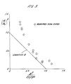
- the radius R B of the passage portion 2 was 17 mm and the radius R E of the passage portion 3 was 6.5 mm.
- Flow rates ⁇ were measured for different metal depths h and values of the field B. These values were non-dimensionalised by the flow rate ⁇ o for zero field and the same metal depth. The square of this ratio ( ⁇ / ⁇ o )2 is plotted against B2/2 ⁇ gh in Figure 3. For values of B2/2 ⁇ gh up to 0.3 the flow rate increases by approximately 10% and the stream is observed to increase in diameter.
Landscapes
- Physics & Mathematics (AREA)
- Electromagnetism (AREA)
- Engineering & Computer Science (AREA)
- Mechanical Engineering (AREA)
- Magnetically Actuated Valves (AREA)
- Continuous Casting (AREA)
- Valve Device For Special Equipments (AREA)
- Crucibles And Fluidized-Bed Furnaces (AREA)
- Reciprocating, Oscillating Or Vibrating Motors (AREA)
Claims (4)
- Elektromagnetisches Ventil für die Benutzung beim Abziehen von geschmolzenem Metall aus einem Behälter, mit einem Körper (1), welcher einen Abzugsdurchlaß (2, 3) aufweist, durch welchen bei der Benutzung geschmolzenes Metall aus dem Behälter unter der Einwirkung der Schwerkraft abfließt; einer elektrischen Induktionsspule 4, die um den Durchlaß (2, 3) angeordnet ist; und einer Vorrichtung zum Zuführen eines hochfrequenten elektrischen Stromes zur Spule 4, wodurch die Spule 4 ein alternierendes Magnetfeld schafft, welches elektrische Ströme im geschmolzenen Metall im Durchlaß (2, 3) induzierte, wobei die Wechselwirkung zwischen dem Feld und den Strömen eine Kraft erzeugt, die das geschmolzene Metall weg von der Wandung des Durchlasses (2, 3) zu dessen Achse drängt,
dadurch gekennzeichnet, daß der Durchlaß einen ersten Teil 2 mit einem Radius RB neben dem Behälter und einen zweiten Teil (3) mit einem geringeren Radius RE, der sich vom ersten Teil (2) zum freien Ende des Durchlasses (2, 3) erstreckt, aufweist. - Ventil nach Anspruch 1,
dadurch gekennzeichnet, daß die Zuführvorrichtung einen elektrischen Strom mit einer solchen Frequenz zuführt, daß die Durchdringung des Feldes in das geschmolzene Metall in dem Durchlaß (2, 3), gemessen durch die Hautdichte δ ein Bruchteil von RB - RE ist. - Ventil nach einem der Ansprüche 1 oder 2,
dadurch gekennzeichnet, daß die Frequenz (f) des Stromes die folgende Gleichung erfüllt: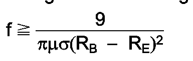
- Ventil nach Anspruch 3,
dadurch gekennzeichnet, daß die Frequenz des Stromes die folgende Gleichung erfüllt:
Priority Applications (1)
| Application Number | Priority Date | Filing Date | Title |
|---|---|---|---|
| AT89303666T ATE85918T1 (de) | 1988-04-25 | 1989-04-13 | Elektromagnetisches ventil. |
Applications Claiming Priority (2)
| Application Number | Priority Date | Filing Date | Title |
|---|---|---|---|
| GB8809693A GB2218019B (en) | 1988-04-25 | 1988-04-25 | Electromagnetic valve |
| GB8809693 | 1988-04-25 |
Publications (3)
| Publication Number | Publication Date |
|---|---|
| EP0339837A2 EP0339837A2 (de) | 1989-11-02 |
| EP0339837A3 EP0339837A3 (en) | 1990-12-05 |
| EP0339837B1 true EP0339837B1 (de) | 1993-02-24 |
Family
ID=10635771
Family Applications (1)
| Application Number | Title | Priority Date | Filing Date |
|---|---|---|---|
| EP19890303666 Expired - Lifetime EP0339837B1 (de) | 1988-04-25 | 1989-04-13 | Elektromagnetisches Ventil |
Country Status (7)
| Country | Link |
|---|---|
| US (1) | US4947895A (de) |
| EP (1) | EP0339837B1 (de) |
| JP (1) | JPH0221084A (de) |
| AT (1) | ATE85918T1 (de) |
| DE (1) | DE68904977T2 (de) |
| ES (1) | ES2038407T3 (de) |
| GB (1) | GB2218019B (de) |
Cited By (3)
| Publication number | Priority date | Publication date | Assignee | Title |
|---|---|---|---|---|
| DE19603317A1 (de) * | 1995-08-28 | 1997-03-06 | Didier Werke Ag | Verfahren zum Betreiben eines Induktors und Induktor zur Durchführung des Verfahrens |
| EP0761347A1 (de) * | 1995-08-28 | 1997-03-12 | Didier-Werke Ag | Verfahren zum Betreiben eines Induktors und Induktor zur Durchführung des Verfahrens |
| US6226314B1 (en) | 1995-08-28 | 2001-05-01 | Didier-Werke Ag | Assembly of a tapping device and a cooled inductor |
Families Citing this family (10)
| Publication number | Priority date | Publication date | Assignee | Title |
|---|---|---|---|---|
| FR2647874B1 (fr) * | 1989-06-02 | 1991-09-20 | Galva Lorraine | Vanne electromagnetique pour controler l'ecoulement d'un metal ou alliage metallique en phase liquide dans une canalisation en charge |
| DZ1422A1 (fr) * | 1989-06-09 | 2004-09-13 | Galva Lorraine | Procédé, enciente et installation pour le revêtement continu/intermittent d'objets par passage desdits objets à travers une masse liquide d'un produitde revêtement. |
| US5137045A (en) * | 1991-10-31 | 1992-08-11 | Inland Steel Company | Electromagnetic metering of molten metal |
| US5235954A (en) * | 1992-07-09 | 1993-08-17 | Anatoly Sverdlin | Integrated automated fuel system for internal combustion engines |
| US5350159A (en) * | 1993-02-18 | 1994-09-27 | Westinghouse Electric Corporation | On/off valve apparatus for use in conjunction with electromagnetic flow control device controlling the flow of liquid metal through an orifice |
| US5398726A (en) * | 1993-03-05 | 1995-03-21 | Sussman; Arthur | Pressure noise suppression valve |
| GB2312861B (en) * | 1996-05-08 | 1999-08-04 | Keith Richard Whittington | Valves |
| US6321766B1 (en) | 1997-02-11 | 2001-11-27 | Richard D. Nathenson | Electromagnetic flow control valve for a liquid metal with built-in flow measurement |
| US6044858A (en) * | 1997-02-11 | 2000-04-04 | Concept Engineering Group, Inc. | Electromagnetic flow control valve for a liquid metal |
| DE102008037259A1 (de) * | 2008-08-08 | 2010-02-25 | Doncasters Precision Castings-Bochum Gmbh | Elektromagnetischer Stopfen |
Family Cites Families (9)
| Publication number | Priority date | Publication date | Assignee | Title |
|---|---|---|---|---|
| GB777213A (en) * | 1952-04-09 | 1957-06-19 | Birlec Ltd | A new or improved method of, and apparatus for, controlling or preventing the discharge of molten metal from containers |
| US3520316A (en) * | 1963-12-12 | 1970-07-14 | Bowles Eng Corp | Pressure-to-pressure transducer |
| US3701357A (en) * | 1968-09-30 | 1972-10-31 | Asea Ab | Electromagnetic valve means for tapping molten metal |
| GB1348331A (en) * | 1972-01-24 | 1974-03-13 | Ass Elect Ind | Production of a stream of molten metal |
| GB1481301A (en) * | 1973-07-16 | 1977-07-27 | Bicc Ltd | Method of and apparatus for casting metals |
| FR2316026A1 (fr) * | 1975-07-04 | 1977-01-28 | Anvar | Dispositif electromagnetique de confinement des metaux liquides |
| FR2457730A1 (fr) * | 1979-05-31 | 1980-12-26 | Anvar | Procede et dispositif pour realiser le confinement des metaux liquides par mise en oeuvre d'un champ electromagnetique |
| CH665369A5 (de) * | 1984-03-07 | 1988-05-13 | Concast Standard Ag | Verfahren zur regelung des durchflusses einer metallschmelze beim stranggiessen, und eine vorrichtung zur durchfuehrung des verfahrens. |
| GB8711041D0 (en) * | 1987-05-11 | 1987-06-17 | Electricity Council | Electromagnetic valve |
-
1988
- 1988-04-25 GB GB8809693A patent/GB2218019B/en not_active Expired - Fee Related
-
1989
- 1989-04-13 AT AT89303666T patent/ATE85918T1/de not_active IP Right Cessation
- 1989-04-13 ES ES89303666T patent/ES2038407T3/es not_active Expired - Lifetime
- 1989-04-13 EP EP19890303666 patent/EP0339837B1/de not_active Expired - Lifetime
- 1989-04-13 DE DE8989303666T patent/DE68904977T2/de not_active Expired - Fee Related
- 1989-04-21 US US07/341,780 patent/US4947895A/en not_active Expired - Fee Related
- 1989-04-25 JP JP1105721A patent/JPH0221084A/ja active Pending
Cited By (5)
| Publication number | Priority date | Publication date | Assignee | Title |
|---|---|---|---|---|
| DE19603317A1 (de) * | 1995-08-28 | 1997-03-06 | Didier Werke Ag | Verfahren zum Betreiben eines Induktors und Induktor zur Durchführung des Verfahrens |
| EP0761347A1 (de) * | 1995-08-28 | 1997-03-12 | Didier-Werke Ag | Verfahren zum Betreiben eines Induktors und Induktor zur Durchführung des Verfahrens |
| US6051822A (en) * | 1995-08-28 | 2000-04-18 | Didier-Werke Ag | Method of operating an inductor |
| US6072166A (en) * | 1995-08-28 | 2000-06-06 | Didier-Werke Ag | Method of operating an inductor |
| US6226314B1 (en) | 1995-08-28 | 2001-05-01 | Didier-Werke Ag | Assembly of a tapping device and a cooled inductor |
Also Published As
| Publication number | Publication date |
|---|---|
| EP0339837A2 (de) | 1989-11-02 |
| US4947895A (en) | 1990-08-14 |
| DE68904977T2 (de) | 1993-09-09 |
| ATE85918T1 (de) | 1993-03-15 |
| EP0339837A3 (en) | 1990-12-05 |
| GB8809693D0 (en) | 1988-06-02 |
| JPH0221084A (ja) | 1990-01-24 |
| DE68904977D1 (de) | 1993-04-01 |
| GB2218019A (en) | 1989-11-08 |
| GB2218019B (en) | 1992-01-08 |
| ES2038407T3 (es) | 1993-07-16 |
Similar Documents
| Publication | Publication Date | Title |
|---|---|---|
| EP0339837B1 (de) | Elektromagnetisches Ventil | |
| EP0291289B1 (de) | Elektromagnetisches Ventil | |
| ATE32500T1 (de) | Verfahren zur regelung des durchflusses einer elektrisch leitenden fluessigkeit, insbesondere einer metallschmelze beim stranggiessen, und eine vorrichtung zur durchfuehrung des verfahrens. | |
| EP0298373A2 (de) | Elektromagnetische Fliess-Kontrolleinrichtung für flüssiges Metall in Verbindung mit einem Pumpvorgang | |
| US5074532A (en) | Electro-magnetic nozzle device for controlling a stream of liquid metal tapped from a crucible | |
| US5003551A (en) | Induction melting of metals without a crucible | |
| EP2218528B1 (de) | Elektromagnetische spulenvorrichtung zur verwendung bei in der form geschmolzenem stahl, die sowohl als elektromagnetische rührvorrichtung als auch als elektromagnetische bremse dienen kann | |
| EP1021574B1 (de) | Vorrichtung und verfahren zum rühren von geschmolzenen metall mittels eines elektromagnetischen feldes | |
| KR100193088B1 (ko) | 수직자장을 이용하여 용융금속을 가두는 장치 및 방법 | |
| US5528620A (en) | Levitating and melting apparatus and method of operating the same | |
| US4561489A (en) | Flux concentrator | |
| EP0445328A1 (de) | Verfahren für das Stranggiessen von Stahl | |
| Kim et al. | A Numerical Prediction of Electromagnetically Driven Flow in ASES-SKF Ladle Refining by Straight Induction Stirrer | |
| US4446909A (en) | Process and apparatus for electromagnetic casting of multiple strands having individual head control | |
| JPH0428460A (ja) | 溶融金属渦流の防止装置とその防止方法 | |
| WO1997041985A1 (en) | Electromagnetic valve | |
| EP0058899B1 (de) | Verfahren und Einrichtung zum elektromagnetischen Giessen von mehreren Strängen mit individueller Formsteuerung | |
| WO2000071761A8 (en) | Electromagnetic braking process in the outlet channel of a furnace | |
| Suh et al. | Suppression of the vortex in ladle by static magnetic field | |
| US4319625A (en) | Electromagnetic casting process utilizing an active transformer-driven copper shield | |
| US4452297A (en) | Process and apparatus for selecting the drive frequencies for individual electromagnetic containment inductors | |
| KR970007154B1 (ko) | 전자기력을 이용한 진공 탈가스장치의 용강가속 환류장치 | |
| SU782951A1 (ru) | Способ непрерывной разливки металлов | |
| US4518030A (en) | Multi-turn coils of controlled pitch for electromagnetic casting | |
| US5601140A (en) | Apparatus for efficient sidewall containment of molten metal with horizontal alternating magnetic fields utilizing a ferromagnetic dam |
Legal Events
| Date | Code | Title | Description |
|---|---|---|---|
| PUAI | Public reference made under article 153(3) epc to a published international application that has entered the european phase |
Free format text: ORIGINAL CODE: 0009012 |
|
| AK | Designated contracting states |
Kind code of ref document: A2 Designated state(s): AT BE CH DE ES FR GB GR IT LI LU NL SE |
|
| PUAL | Search report despatched |
Free format text: ORIGINAL CODE: 0009013 |
|
| AK | Designated contracting states |
Kind code of ref document: A3 Designated state(s): AT BE CH DE ES FR GB GR IT LI LU NL SE |
|
| 17P | Request for examination filed |
Effective date: 19910104 |
|
| 17Q | First examination report despatched |
Effective date: 19920513 |
|
| RAP1 | Party data changed (applicant data changed or rights of an application transferred) |
Owner name: ELECTRICITY ASSOCIATION SERVICES LIMITED |
|
| GRAA | (expected) grant |
Free format text: ORIGINAL CODE: 0009210 |
|
| AK | Designated contracting states |
Kind code of ref document: B1 Designated state(s): AT BE CH DE ES FR GR IT LI LU NL SE |
|
| PG25 | Lapsed in a contracting state [announced via postgrant information from national office to epo] |
Ref country code: SE Effective date: 19930224 Ref country code: LI Effective date: 19930224 Ref country code: GR Free format text: LAPSE BECAUSE OF FAILURE TO SUBMIT A TRANSLATION OF THE DESCRIPTION OR TO PAY THE FEE WITHIN THE PRESCRIBED TIME-LIMIT Effective date: 19930224 Ref country code: CH Effective date: 19930224 Ref country code: AT Effective date: 19930224 |
|
| REF | Corresponds to: |
Ref document number: 85918 Country of ref document: AT Date of ref document: 19930315 Kind code of ref document: T |
|
| ITF | It: translation for a ep patent filed | ||
| PGFP | Annual fee paid to national office [announced via postgrant information from national office to epo] |
Ref country code: BE Payment date: 19930323 Year of fee payment: 5 |
|
| REF | Corresponds to: |
Ref document number: 68904977 Country of ref document: DE Date of ref document: 19930401 |
|
| PGFP | Annual fee paid to national office [announced via postgrant information from national office to epo] |
Ref country code: ES Payment date: 19930407 Year of fee payment: 5 |
|
| PGFP | Annual fee paid to national office [announced via postgrant information from national office to epo] |
Ref country code: FR Payment date: 19930429 Year of fee payment: 5 |
|
| ET | Fr: translation filed | ||
| PG25 | Lapsed in a contracting state [announced via postgrant information from national office to epo] |
Ref country code: LU Free format text: LAPSE BECAUSE OF NON-PAYMENT OF DUE FEES Effective date: 19930430 |
|
| PGFP | Annual fee paid to national office [announced via postgrant information from national office to epo] |
Ref country code: NL Payment date: 19930430 Year of fee payment: 5 |
|
| REG | Reference to a national code |
Ref country code: CH Ref legal event code: PL |
|
| PGFP | Annual fee paid to national office [announced via postgrant information from national office to epo] |
Ref country code: DE Payment date: 19930623 Year of fee payment: 5 |
|
| REG | Reference to a national code |
Ref country code: ES Ref legal event code: FG2A Ref document number: 2038407 Country of ref document: ES Kind code of ref document: T3 |
|
| PLBE | No opposition filed within time limit |
Free format text: ORIGINAL CODE: 0009261 |
|
| STAA | Information on the status of an ep patent application or granted ep patent |
Free format text: STATUS: NO OPPOSITION FILED WITHIN TIME LIMIT |
|
| 26N | No opposition filed | ||
| PG25 | Lapsed in a contracting state [announced via postgrant information from national office to epo] |
Ref country code: ES Free format text: LAPSE BECAUSE OF NON-PAYMENT OF DUE FEES Effective date: 19940414 |
|
| PG25 | Lapsed in a contracting state [announced via postgrant information from national office to epo] |
Ref country code: BE Effective date: 19940430 |
|
| BERE | Be: lapsed |
Owner name: ELECTRICITY ASSOCIATION SERVICES LTD Effective date: 19940430 |
|
| PG25 | Lapsed in a contracting state [announced via postgrant information from national office to epo] |
Ref country code: NL Effective date: 19941101 |
|
| NLV4 | Nl: lapsed or anulled due to non-payment of the annual fee | ||
| PG25 | Lapsed in a contracting state [announced via postgrant information from national office to epo] |
Ref country code: FR Effective date: 19941229 |
|
| PG25 | Lapsed in a contracting state [announced via postgrant information from national office to epo] |
Ref country code: DE Effective date: 19950103 |
|
| REG | Reference to a national code |
Ref country code: FR Ref legal event code: ST |
|
| REG | Reference to a national code |
Ref country code: ES Ref legal event code: FD2A Effective date: 19990301 |
|
| PG25 | Lapsed in a contracting state [announced via postgrant information from national office to epo] |
Ref country code: IT Free format text: LAPSE BECAUSE OF NON-PAYMENT OF DUE FEES;WARNING: LAPSES OF ITALIAN PATENTS WITH EFFECTIVE DATE BEFORE 2007 MAY HAVE OCCURRED AT ANY TIME BEFORE 2007. THE CORRECT EFFECTIVE DATE MAY BE DIFFERENT FROM THE ONE RECORDED. Effective date: 20050413 |