EP0339329A2 - Rundfunkempfänger mit einem Decoder - Google Patents
Rundfunkempfänger mit einem Decoder Download PDFInfo
- Publication number
- EP0339329A2 EP0339329A2 EP89106116A EP89106116A EP0339329A2 EP 0339329 A2 EP0339329 A2 EP 0339329A2 EP 89106116 A EP89106116 A EP 89106116A EP 89106116 A EP89106116 A EP 89106116A EP 0339329 A2 EP0339329 A2 EP 0339329A2
- Authority
- EP
- European Patent Office
- Prior art keywords
- identifier
- signal
- decoder
- radio
- radio receiver
- Prior art date
- Legal status (The legal status is an assumption and is not a legal conclusion. Google has not performed a legal analysis and makes no representation as to the accuracy of the status listed.)
- Granted
Links
- 238000001514 detection method Methods 0.000 claims description 4
- 230000005540 biological transmission Effects 0.000 description 3
- 238000010586 diagram Methods 0.000 description 1
- 238000000034 method Methods 0.000 description 1
- 230000000717 retained effect Effects 0.000 description 1
- 230000008054 signal transmission Effects 0.000 description 1
- 230000001960 triggered effect Effects 0.000 description 1
Images
Classifications
-
- H—ELECTRICITY
- H03—ELECTRONIC CIRCUITRY
- H03J—TUNING RESONANT CIRCUITS; SELECTING RESONANT CIRCUITS
- H03J1/00—Details of adjusting, driving, indicating, or mechanical control arrangements for resonant circuits in general
- H03J1/0008—Details of adjusting, driving, indicating, or mechanical control arrangements for resonant circuits in general using a central processing unit, e.g. a microprocessor
- H03J1/0058—Details of adjusting, driving, indicating, or mechanical control arrangements for resonant circuits in general using a central processing unit, e.g. a microprocessor provided with channel identification means
-
- H—ELECTRICITY
- H04—ELECTRIC COMMUNICATION TECHNIQUE
- H04H—BROADCAST COMMUNICATION
- H04H20/00—Arrangements for broadcast or for distribution combined with broadcast
- H04H20/53—Arrangements specially adapted for specific applications, e.g. for traffic information or for mobile receivers
- H04H20/55—Arrangements specially adapted for specific applications, e.g. for traffic information or for mobile receivers for traffic information
-
- H—ELECTRICITY
- H04—ELECTRIC COMMUNICATION TECHNIQUE
- H04H—BROADCAST COMMUNICATION
- H04H20/00—Arrangements for broadcast or for distribution combined with broadcast
- H04H20/28—Arrangements for simultaneous broadcast of plural pieces of information
- H04H20/33—Arrangements for simultaneous broadcast of plural pieces of information by plural channels
- H04H20/34—Arrangements for simultaneous broadcast of plural pieces of information by plural channels using an out-of-band subcarrier signal
-
- H—ELECTRICITY
- H04—ELECTRIC COMMUNICATION TECHNIQUE
- H04H—BROADCAST COMMUNICATION
- H04H2201/00—Aspects of broadcast communication
- H04H2201/10—Aspects of broadcast communication characterised by the type of broadcast system
- H04H2201/13—Aspects of broadcast communication characterised by the type of broadcast system radio data system/radio broadcast data system [RDS/RBDS]
-
- H—ELECTRICITY
- H04—ELECTRIC COMMUNICATION TECHNIQUE
- H04H—BROADCAST COMMUNICATION
- H04H40/00—Arrangements specially adapted for receiving broadcast information
- H04H40/18—Arrangements characterised by circuits or components specially adapted for receiving
Definitions
- the subject of property rights belongs to the field of radio receivers, which is defined in claim 1.
- Radio receivers of this type are known from DE PS 22 29 796.
- the circuit specified there works with a time delay element, which consists of an RC network. A certain time delay is predetermined by the dimensioning of this network.
- a pilot signal When designing the circuit, it is assumed that certain transmitters are identified by a pilot signal.
- the pilot signal In the course of the further development of the signal transmission in the FM radio area, the pilot signal, the 57 kHz subcarrier of the traffic radio stations, is now modulated in amplitude with an area identifier and sometimes with an announcement identifier and, according to recent proposals, also with the RDS signal.
- the transmission of the traffic radio code takes place according to the teaching of claim 1 of DBP 20 51 034, the transmission of the RDS signal according to claim 2 of the same patent.
- announcements from traffic reports In addition to the marking of announcements from traffic reports, it has already been discussed to mark the announcements of other reports, in particular general warning reports. For system-related reasons, the distinction between the different announcement identifiers requires a longer recognition time than the recognition of an area identifier.
- identification signals for various properties of the transmitter or the program that a search could search for are transmitted one after the other and repeated a different number of times, depending on the group of the RDS signal in which the identification signal is transmitted.
- the object of the invention was to solve the known circuit from the dimensioning to the very rarely transmitted identification signals or to the recognition of different announcement identifications and to accelerate the station search process.
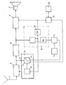
- FIG. 1 This solution is explained in more detail with the aid of a block diagram, FIG. 1.
- the antenna 1 When the radio transmitter is received, the antenna 1 generates an input signal for the radio receiver, which comprises an HF part 2, an IF part 3 and an LF part 4, to which the loudspeaker 5 is connected.
- a 57 kHz subcarrier can also be tapped at the output of the IF part 3, which in the exemplary embodiment has a range identifier in the frequency range of approximately 20-50 Hz and from time to time Announcement identifiers of 125 Hz and above are modulated in amplitude.
- the 57 kHz subcarrier is demodulated in a traffic radio decoder 6 and the area identifier is at one of the two outputs and the announcement identifier is at the other.
- the radio receiver has a so-called active area identification circuit. This consists of a keyboard 7, which can be used to preselect the area identifier that a driver is currently preferring.
- the subcarriers of the transmitters in a certain geographical area are modulated with the same area identifier, in order to indicate that the traffic announcements which these transmitters relate to the same narrow road network.
- the driver can use the keyboard to determine the area identifier and thus the transmitters that transmit traffic messages for the road network in which he is currently traveling.
- the search mode is currently switched on in the receiver.
- the loudspeaker 5 is generally muted.
- the search is first interrupted via a line 15 between the RF stage output and the search control.
- the comparison circuit 9 the preselected area identifier is compared with the area identifier transmitted by the transmitter currently set in the HF part 2, which is pending at the output of the traffic radio decoder 6. If the two match, then in this coincidence the comparison stage 9 triggers an impulse with which the search mode is switched off and the tuning to the transmitter is retained.
- the area identifier modulates the 57 kHz subcarrier in accordance with the standards for traffic radio with 60% in amplitude, while the announcement identifier modulates the subcarrier amplitude only with 30%. This fact leads to the fact that, as a rule, a longer time is required for the recognition of the announcement identifier than for the identification of an area identifier, and even more so for the distinction between two announcement identifiers.
- the fact is used that at the entrance of the announcement recognition stage 61 in the traffic radio decoder 6 the signal which has not yet been recognized is present during the entire recognition time.
- the time constant for the automatic advance 11 is extended.
- the input signal of the announcement detection stage 61 of the traffic radio decoder 6 is also present at a timer 10 of the automatic advance 11 and causes an extension of the waiting time which is available for the detection of the identification signal.
- the search run is started again automatically, provided that the automatic advance 11 in the search run control 8 is not blocked by the coincidence signal of the comparison stage 9 or by the recognized announcement identifier.
- the output of the announcement detection stage 61 is connected in parallel with the output of the comparison stage 9 to an OR stage 12 located before the input of the automatic switching mechanism 11.
- a different announcement identifier deviating from 125 Hz, is used to identify the transmission of such a hazard message, which modulates the amplitude of the 57 kHz subcarrier by 30%.
- this second announcement identifier is preselected in a second keyboard 13 (or in a second mode of the first keyboard 7), the signal at the output of the announcement recognition stage 61 is compared in a comparison stage 14 with the preselected announcement identifier. In the event of a coincidence, the search will then certainly stop on a station that is currently broadcasting a warning message and for as long as the warning message is being broadcast.
Landscapes
- Engineering & Computer Science (AREA)
- Computer Hardware Design (AREA)
- Microelectronics & Electronic Packaging (AREA)
- Signal Processing (AREA)
- Circuits Of Receivers In General (AREA)
- Television Systems (AREA)
- Input Circuits Of Receivers And Coupling Of Receivers And Audio Equipment (AREA)
- Selective Calling Equipment (AREA)
- Mobile Radio Communication Systems (AREA)
Abstract
Description
- Der Gegenstand des Schutzrechts gehört zu dem Bereich der Rundfunkempfänger, der im Patentanspruch 1 näher bestimmt ist.
- Rundfunkempfänger dieser Art sind aus der DE PS 22 29 796 bekannt. Die dort angegebene Schaltung arbeitet mit einem Zeitverzögerungsglied, das aus einem RC-Netzwerk besteht. Durch die Dimensionierung dieses Netzwerkes ist eine bestimmte Zeitverzögerung vorgegeben. Bei der Konzeption der Schaltung geht man davon aus, daß bestimmte Sender durch ein Pilotsignal gekennzeichnet sind.
- Im Zuge der Weiterentwicklung der Signalübertragung im UKW-Rundfunkbereich wird inzwischen das Pilotsignal, der 57-kHz-Hilfsträger der Verkehrsfunksender, mit einer Bereichskennung und zeitweise mit einer Durchsagekennung in der Amplitude moduliert und nach neueren Vorschlägen auch mit dem RDS-Signal. Die Übertragung der Verkehrsfunkkennung erfolgt nach der Lehre des Anspruchs 1 des DBP 20 51 034, die Übertragung des RDS-Signals nach Anspruch 2 desselben Patents.
- Es wurde bereits diskutiert, neben der Kennzeichnung von Durchsagen von Verkehrsmeldungen, die Durchsagen anderer Meldungen, insbesondere allgemeiner Warnmeldungen zu kennzeichnen. Die Unterscheidung zwischen den verschiedenen Durchsagekennungen benötigt aus systembedingten Gründen eine längere Erkennungszeit als die Erkennung einer Bereichskennung.
- Im RDS-Signal werden Kennsignale für verschiedene Eigenschaften des Senders bzw. der Sendung, nach denen ein Suchlauf suchen könnte, nacheinander übertragen und unterschiedlich häufig wiederholt, je nachdem, in welcher Gruppe des RDS-Signals das Kennsignal übertragen wird.
- Der Erfindung lag nun die Aufgabe zugrunde, die bekannte Schaltung von der Dimensionierung auf die sehr selten übertragenen Kennsignalen oder auf die Erkennung unterschiedlicher Durchsagekennungen zu lösen und den Sendersuchlaufvorgang zu beschleunigen.
- Die Lösung dieser Aufgabe gemäß der Erfindung ist im kennzeichnenden Teil des Anspruchs 1 näher angegeben.
- Anhand eines Blockschaltbildes, Figur 1, wird diese Lösung ausführlicher erläutert.
- Die Antenne 1 erzeugt bei dem Empfang der Rundfunksender ein Eingangssignal für den Rundfunkempfänger, der ein HF-Teil 2, ein ZF-Teil 3 und ein NF-Teil 4 umfaßt, an den der Lautsprecher 5 angeschlossen ist.
- Am Ausgang des ZF-Teils 3 ist bei Verkehrsfunk- oder RDS-Sendern neben dem NF-Signal auch ein 57-kHz-Hilfsträger abgreifbar, der im Ausführungsbeispiel dauernd mit einer Bereichskennung im Frequenzbereich von etwa 20 - 50 Hz und von Zeit zu Zeit mit Durchsagekennungen von 125 Hz und darüber in der Amplitude moduliert ist.
- In einem Verkehrsfunkdecoder 6 wird der 57-kHz-Hilfsträger demoduliert und an dem einen der beiden Ausgänge steht die Bereichskennung, am anderen die Durchsagekennung an.
- Der Rundfunkempfänger verfügt über eine sogenannte aktive Bereichskennungsschaltung. Diese besteht aus einer Tastatur 7, mit der die Bereichskennung vorgewählt werden kann, die ein Autofahrer gerade bevorzugt.
- Zum leichteren Verständnis sei kurz erläutert, daß die Hilfsträger der Sender in einem bestimmten geografischen Bereich mit der gleichen Bereichskennung moduliert sind, um damit kenntlich zu machen, daß die Verkehrsmeldungen, die diese Sender übertragen, sich auf dasselbe engere Straßennetz beziehen. Der Autofahrer kann mit der Tastatur die Bereichskennung und damit die Sender bestimmen, die ihm Verkehrsnachrichten für das Straßennetz übermitteln, in dem er sich gerade bewegt.
- Für die weitere Erläuterung wird davon ausgegangen, daß im Empfänger gerade der Suchlaufmode eingeschaltet ist. In diesem Suchlaufmode ist der Lautsprecher 5 in der Regel stummgeschaltet. Hat der Empfänger während des von der Suchlaufsteuerung 8 ausgelösten Suchlaufs den Empfang eines Trägers eines Rundfunksenders festgestellt, so wird der Suchlauf zunächst über eine Leitung 15 zwischen dem HF-Stufenausgang und der Suchlaufsteuerung unterbrochen. In der Vergleichsschaltung 9 wird die vorgewählte Bereichskennung mit dem vom gerade im HF-Teil 2 eingestellten Sender übermittelten Bereichskennung, die am Ausgang des Verkehrsfunkdecoders 6 ansteht, verglichen. Stimmen beide überein, so löst in diesem Koinzidenzfall die Vergleichsstufe 9 einen Impuls aus, mit dem der Suchlaufmode abgeschaltet wird und die Abstimmung auf den Sender erhalten bleibt.
- Die Bereichskennung moduliert bekanntlich den 57-kHz-Hilfsträger entsprechend den Normen für den Verkehrsfunk mit 60 % in der Amplitude, die Durchsagekennung die Hilfsträgeramplitude dagegen nur mit 30 %. Diese Tatsache führt dazu, daß schon in alier Regel für die Erkennung der Durchsagekennung eine längere Zeit erforderlich ist als für die Erkennung einer Bereichskennung, erst recht jedoch für die Unterscheidung zweier Durchsagekennungen.
- In dem erfindungsgemäßen Rundfunkempfänger wird die Tatsache ausgenutzt, daß am Eingang der Durchsageerkennungsstufe 61 im Verkehrsfunkdecoder 6 während der ganzen Erkennungszeit das noch nicht erkannte Signal bereits ansteht. Beim Auftreten dieses Signals wird die Zeitkonstante für die Fortschaltautomatik 11 verlängert. Dazu liegt das Eingangssignal der Durchsageerkennungstufe 61 des Verkehrsfunkdecoders 6 auch an einem Zeitglied 10 der Fortschaltautomatik 11 an und bewirkt eine Verlängerung der Wartezeit, die für die Erkennung des Kennsignals zur Verfügung steht.
- Nach Ablauf dieser Wartezeit wird der Suchlauf wieder automatisch gestartet, sofern die Fortschaltautomatik 11 in der Suchlaufsteuerung 8 nicht durch das Koinzidenzsignal der Vergleichsstufe 9 oder durch die erkannte Durchsagekennung blockiert bleibt. Dazu ist der Ausgang der Durchsageerkennungsstufe 61 parallel zum Ausgang der Vergleichsstufe 9 mit einer vor dem Eingang der Fortschaltautomatik 11 liegenden Oderstufe 12 verbunden.
- Wenn die Rundfunksender nicht nur Verkehrsmeldungen übermitteln, sondern auch andere Gefahrenmeldungen, dann sollte deren Empfang unter allen Umständen gewährleistet sein, auch im Suchlaufmode. Für die Kennzeichnung der Übertragung einer solchen Gefahrenmeldung dient eine andere, von 125 Hz abweichende, Durchsagekennung, die den 57-kHz-Hilfsträger zu 30 % in der Amplitude moduliert.
- Wird diese zweite Durchsagekennung in einer zweiten Tastatur 13 (oder in einem zweiten Mode der ersten Tastatur 7) vorgewählt, so wird das Signal am Ausgang der Durchsageerkennungsstufe 61 in einer Vergleichsstufe 14 mit der vorgewählten Durchsagekennung verglichen. Im Koinzidenzfall hält dann der Suchlauf mit Sicherheit auf einem Sender, der gerade eine Warnmeldung verbreitet und solange die Warnmeldung ausgestrahlt wird.
Claims (2)
dadurch gekennzeichnet,
daß das Zeitglied (10) der Fortschaltautomatik (11) in Abhängigkeit von der empfangenen Kennung zwischen verschiedenen Werten der Zeitkonstanten umschaltbar ist.
dadurch gekennzeichnet,
daß in Abhängigkeit von einem Signal am Eingang der Durchsageerkennungsstufe (61) im Verkehrsfunkdecoder (6) die Zeitkonstante im Zeitglied (10) in der Fortschaltautomatik (8) vergrößert ist.
Applications Claiming Priority (2)
| Application Number | Priority Date | Filing Date | Title |
|---|---|---|---|
| DE3813783 | 1988-04-23 | ||
| DE3813783A DE3813783A1 (de) | 1988-04-23 | 1988-04-23 | Rundfunkempfaenger |
Publications (3)
| Publication Number | Publication Date |
|---|---|
| EP0339329A2 true EP0339329A2 (de) | 1989-11-02 |
| EP0339329A3 EP0339329A3 (de) | 1990-09-26 |
| EP0339329B1 EP0339329B1 (de) | 1997-02-05 |
Family
ID=6352750
Family Applications (1)
| Application Number | Title | Priority Date | Filing Date |
|---|---|---|---|
| EP89106116A Expired - Lifetime EP0339329B1 (de) | 1988-04-23 | 1989-04-07 | Rundfunkempfänger mit einem Decoder |
Country Status (4)
| Country | Link |
|---|---|
| EP (1) | EP0339329B1 (de) |
| AT (1) | ATE148814T1 (de) |
| DE (2) | DE3813783A1 (de) |
| ES (1) | ES2097737T3 (de) |
Family Cites Families (4)
| Publication number | Priority date | Publication date | Assignee | Title |
|---|---|---|---|---|
| DE2051034C3 (de) * | 1970-10-17 | 1978-11-02 | Hessischer Rundfunk, 6000 Frankfurt | UKW-Rundfunk-Stereophonie-Übertragungssystem |
| DE3019770A1 (de) * | 1980-05-23 | 1981-12-03 | Blaupunkt-Werke Gmbh, 3200 Hildesheim | Suchlaufempfaenger fuer verkehrsfunksender |
| DE3517736A1 (de) * | 1985-05-17 | 1986-12-18 | Grundig E.M.V. Elektro-Mechanische Versuchsanstalt Max Grundig holländ. Stiftung & Co KG, 8510 Fürth | Mobil einsetzbarer rundfunkempfaenger mit verzoegertem suchlaufstart |
| DE3616592A1 (de) * | 1986-05-16 | 1987-11-19 | Blaupunkt Werke Gmbh | Verfahren und schaltungsanordnung zur abstimmung eines autoradios |
-
1988
- 1988-04-23 DE DE3813783A patent/DE3813783A1/de not_active Ceased
-
1989
- 1989-04-07 AT AT89106116T patent/ATE148814T1/de not_active IP Right Cessation
- 1989-04-07 ES ES89106116T patent/ES2097737T3/es not_active Expired - Lifetime
- 1989-04-07 DE DE58909776T patent/DE58909776D1/de not_active Expired - Fee Related
- 1989-04-07 EP EP89106116A patent/EP0339329B1/de not_active Expired - Lifetime
Also Published As
| Publication number | Publication date |
|---|---|
| ATE148814T1 (de) | 1997-02-15 |
| EP0339329B1 (de) | 1997-02-05 |
| DE3813783A1 (de) | 1989-11-02 |
| DE58909776D1 (de) | 1997-03-20 |
| EP0339329A3 (de) | 1990-09-26 |
| ES2097737T3 (es) | 1997-04-16 |
Similar Documents
| Publication | Publication Date | Title |
|---|---|---|
| DE3121088C2 (de) | UKW-Empfänger | |
| DE3121034C2 (de) | UKW-Empfänger | |
| EP0497116B1 (de) | RDS-Rundfunkempfänger | |
| DE2746282A1 (de) | Verkehrsfunkempfaenger | |
| DE3144289C2 (de) | ||
| DE3211813C2 (de) | ||
| DE2240941C3 (de) | Verfahren zur Kennzeichnung von Verkehrsfunkbereichen | |
| DE3143468C2 (de) | ||
| DE3942339C2 (de) | ||
| EP0339329B1 (de) | Rundfunkempfänger mit einem Decoder | |
| DE2460983A1 (de) | Rundfunkempfangsgeraet | |
| DE3906780C1 (de) | ||
| DE2651817A1 (de) | Verkehrsfunkempfaenger | |
| DE2533946C3 (de) | Zusatzschaltung zum Erkennen eines Pilotsignals | |
| DE4125433C1 (en) | VHF car radio with RDS and traffic news decoders - has memories for diversity reception with automatic switch=over to other transmitting station chain when leaving geographical region | |
| DE2350034C3 (de) | Pilotsignalerkennungsschaltung | |
| DE2453354C3 (de) | Verkehrsrundfunksystem | |
| DE2518101A1 (de) | Verfahren zur senderseitigen fernsteuerung der lautstaerke in empfaengern eines rundfunkuebertragungssystems | |
| DE3915101C1 (en) | Superimposing radio signals in selected region by announcements - determining transmission levels of priority signals needed to cover actual reception levels | |
| DE1957987C (de) | Mono-Stereo-Radioempfänger mit Sendersuchlauf | |
| DE2518104C3 (de) | Nachrichtentechnisches Empfangsgerät mit einem Verkehrsfunkdecoder und einem Gebietskennungsdecoder | |
| DE2447407A1 (de) | Schaltungsanordnung zur erkennung und anzeige eines von einem rundfunksender ausgestrahlten pilotsignals | |
| DE2142310A1 (de) | Verfahren zur kennzeichnung der fahrbahnrichtungszuordnung einer verkehrsmeldung | |
| DE3139869A1 (de) | Autorundfunkempfaenger mit automatischer senderfuehrung fuer verkehrsfunkempfang und automatischer prioritaetsschaltung fuer verkehrsfunkdurchsagen | |
| DE2327214A1 (de) | Verfahren zur nachrichtenuebertragung |
Legal Events
| Date | Code | Title | Description |
|---|---|---|---|
| PUAI | Public reference made under article 153(3) epc to a published international application that has entered the european phase |
Free format text: ORIGINAL CODE: 0009012 |
|
| AK | Designated contracting states |
Kind code of ref document: A2 Designated state(s): AT CH DE ES FR GB IT LI SE |
|
| PUAL | Search report despatched |
Free format text: ORIGINAL CODE: 0009013 |
|
| AK | Designated contracting states |
Kind code of ref document: A3 Designated state(s): AT CH DE ES FR GB IT LI SE |
|
| 17P | Request for examination filed |
Effective date: 19900814 |
|
| 17Q | First examination report despatched |
Effective date: 19921119 |
|
| GRAG | Despatch of communication of intention to grant |
Free format text: ORIGINAL CODE: EPIDOS AGRA |
|
| GRAH | Despatch of communication of intention to grant a patent |
Free format text: ORIGINAL CODE: EPIDOS IGRA |
|
| GRAH | Despatch of communication of intention to grant a patent |
Free format text: ORIGINAL CODE: EPIDOS IGRA |
|
| GRAA | (expected) grant |
Free format text: ORIGINAL CODE: 0009210 |
|
| AK | Designated contracting states |
Kind code of ref document: B1 Designated state(s): AT CH DE ES FR GB IT LI SE |
|
| REF | Corresponds to: |
Ref document number: 148814 Country of ref document: AT Date of ref document: 19970215 Kind code of ref document: T |
|
| REG | Reference to a national code |
Ref country code: CH Ref legal event code: NV Representative=s name: SCINTILLA AG, DIREKTION Ref country code: CH Ref legal event code: EP |
|
| ET | Fr: translation filed | ||
| REF | Corresponds to: |
Ref document number: 58909776 Country of ref document: DE Date of ref document: 19970320 |
|
| REG | Reference to a national code |
Ref country code: ES Ref legal event code: FG2A Ref document number: 2097737 Country of ref document: ES Kind code of ref document: T3 |
|
| ITF | It: translation for a ep patent filed | ||
| GBT | Gb: translation of ep patent filed (gb section 77(6)(a)/1977) |
Effective date: 19970411 |
|
| PLBE | No opposition filed within time limit |
Free format text: ORIGINAL CODE: 0009261 |
|
| STAA | Information on the status of an ep patent application or granted ep patent |
Free format text: STATUS: NO OPPOSITION FILED WITHIN TIME LIMIT |
|
| 26N | No opposition filed | ||
| PGFP | Annual fee paid to national office [announced via postgrant information from national office to epo] |
Ref country code: DE Payment date: 20010625 Year of fee payment: 13 |
|
| REG | Reference to a national code |
Ref country code: GB Ref legal event code: IF02 |
|
| PGFP | Annual fee paid to national office [announced via postgrant information from national office to epo] |
Ref country code: GB Payment date: 20020325 Year of fee payment: 14 |
|
| PGFP | Annual fee paid to national office [announced via postgrant information from national office to epo] |
Ref country code: FR Payment date: 20020417 Year of fee payment: 14 |
|
| PGFP | Annual fee paid to national office [announced via postgrant information from national office to epo] |
Ref country code: CH Payment date: 20020422 Year of fee payment: 14 Ref country code: AT Payment date: 20020422 Year of fee payment: 14 |
|
| PGFP | Annual fee paid to national office [announced via postgrant information from national office to epo] |
Ref country code: SE Payment date: 20020424 Year of fee payment: 14 Ref country code: ES Payment date: 20020424 Year of fee payment: 14 |
|
| PG25 | Lapsed in a contracting state [announced via postgrant information from national office to epo] |
Ref country code: DE Free format text: LAPSE BECAUSE OF NON-PAYMENT OF DUE FEES Effective date: 20021101 |
|
| PG25 | Lapsed in a contracting state [announced via postgrant information from national office to epo] |
Ref country code: GB Free format text: LAPSE BECAUSE OF NON-PAYMENT OF DUE FEES Effective date: 20030407 Ref country code: AT Free format text: LAPSE BECAUSE OF NON-PAYMENT OF DUE FEES Effective date: 20030407 |
|
| PG25 | Lapsed in a contracting state [announced via postgrant information from national office to epo] |
Ref country code: SE Free format text: LAPSE BECAUSE OF NON-PAYMENT OF DUE FEES Effective date: 20030408 Ref country code: ES Free format text: LAPSE BECAUSE OF NON-PAYMENT OF DUE FEES Effective date: 20030408 |
|
| PG25 | Lapsed in a contracting state [announced via postgrant information from national office to epo] |
Ref country code: LI Free format text: LAPSE BECAUSE OF NON-PAYMENT OF DUE FEES Effective date: 20030430 Ref country code: CH Free format text: LAPSE BECAUSE OF NON-PAYMENT OF DUE FEES Effective date: 20030430 |
|
| GBPC | Gb: european patent ceased through non-payment of renewal fee |
Effective date: 20030407 |
|
| EUG | Se: european patent has lapsed | ||
| REG | Reference to a national code |
Ref country code: CH Ref legal event code: PL |
|
| PG25 | Lapsed in a contracting state [announced via postgrant information from national office to epo] |
Ref country code: FR Free format text: LAPSE BECAUSE OF NON-PAYMENT OF DUE FEES Effective date: 20031231 |
|
| REG | Reference to a national code |
Ref country code: FR Ref legal event code: ST |
|
| REG | Reference to a national code |
Ref country code: ES Ref legal event code: FD2A Effective date: 20030408 |
|
| PG25 | Lapsed in a contracting state [announced via postgrant information from national office to epo] |
Ref country code: IT Free format text: LAPSE BECAUSE OF NON-PAYMENT OF DUE FEES;WARNING: LAPSES OF ITALIAN PATENTS WITH EFFECTIVE DATE BEFORE 2007 MAY HAVE OCCURRED AT ANY TIME BEFORE 2007. THE CORRECT EFFECTIVE DATE MAY BE DIFFERENT FROM THE ONE RECORDED. Effective date: 20050407 |