EP0339049B1 - Countershaft transmission - Google Patents
Countershaft transmission Download PDFInfo
- Publication number
- EP0339049B1 EP0339049B1 EP88901512A EP88901512A EP0339049B1 EP 0339049 B1 EP0339049 B1 EP 0339049B1 EP 88901512 A EP88901512 A EP 88901512A EP 88901512 A EP88901512 A EP 88901512A EP 0339049 B1 EP0339049 B1 EP 0339049B1
- Authority
- EP
- European Patent Office
- Prior art keywords
- gear
- gears
- countershaft
- speed
- output shaft
- Prior art date
- Legal status (The legal status is an assumption and is not a legal conclusion. Google has not performed a legal analysis and makes no representation as to the accuracy of the status listed.)
- Expired - Lifetime
Links
Images

Classifications
-
- F—MECHANICAL ENGINEERING; LIGHTING; HEATING; WEAPONS; BLASTING
- F16—ENGINEERING ELEMENTS AND UNITS; GENERAL MEASURES FOR PRODUCING AND MAINTAINING EFFECTIVE FUNCTIONING OF MACHINES OR INSTALLATIONS; THERMAL INSULATION IN GENERAL
- F16H—GEARING
- F16H3/00—Toothed gearings for conveying rotary motion with variable gear ratio or for reversing rotary motion
- F16H3/02—Toothed gearings for conveying rotary motion with variable gear ratio or for reversing rotary motion without gears having orbital motion
- F16H3/08—Toothed gearings for conveying rotary motion with variable gear ratio or for reversing rotary motion without gears having orbital motion exclusively or essentially with continuously meshing gears, that can be disengaged from their shafts
- F16H3/087—Toothed gearings for conveying rotary motion with variable gear ratio or for reversing rotary motion without gears having orbital motion exclusively or essentially with continuously meshing gears, that can be disengaged from their shafts characterised by the disposition of the gears
- F16H3/091—Toothed gearings for conveying rotary motion with variable gear ratio or for reversing rotary motion without gears having orbital motion exclusively or essentially with continuously meshing gears, that can be disengaged from their shafts characterised by the disposition of the gears including a single countershaft
-
- F—MECHANICAL ENGINEERING; LIGHTING; HEATING; WEAPONS; BLASTING
- F16—ENGINEERING ELEMENTS AND UNITS; GENERAL MEASURES FOR PRODUCING AND MAINTAINING EFFECTIVE FUNCTIONING OF MACHINES OR INSTALLATIONS; THERMAL INSULATION IN GENERAL
- F16H—GEARING
- F16H3/00—Toothed gearings for conveying rotary motion with variable gear ratio or for reversing rotary motion
- F16H3/02—Toothed gearings for conveying rotary motion with variable gear ratio or for reversing rotary motion without gears having orbital motion
- F16H3/08—Toothed gearings for conveying rotary motion with variable gear ratio or for reversing rotary motion without gears having orbital motion exclusively or essentially with continuously meshing gears, that can be disengaged from their shafts
- F16H3/087—Toothed gearings for conveying rotary motion with variable gear ratio or for reversing rotary motion without gears having orbital motion exclusively or essentially with continuously meshing gears, that can be disengaged from their shafts characterised by the disposition of the gears
- F16H3/093—Toothed gearings for conveying rotary motion with variable gear ratio or for reversing rotary motion without gears having orbital motion exclusively or essentially with continuously meshing gears, that can be disengaged from their shafts characterised by the disposition of the gears with two or more countershafts
- F16H2003/0936—Toothed gearings for conveying rotary motion with variable gear ratio or for reversing rotary motion without gears having orbital motion exclusively or essentially with continuously meshing gears, that can be disengaged from their shafts characterised by the disposition of the gears with two or more countershafts with multiple countershafts comprising only two idle gears and one gear fixed to the countershaft
-
- Y—GENERAL TAGGING OF NEW TECHNOLOGICAL DEVELOPMENTS; GENERAL TAGGING OF CROSS-SECTIONAL TECHNOLOGIES SPANNING OVER SEVERAL SECTIONS OF THE IPC; TECHNICAL SUBJECTS COVERED BY FORMER USPC CROSS-REFERENCE ART COLLECTIONS [XRACs] AND DIGESTS
- Y10—TECHNICAL SUBJECTS COVERED BY FORMER USPC
- Y10T—TECHNICAL SUBJECTS COVERED BY FORMER US CLASSIFICATION
- Y10T74/00—Machine element or mechanism
- Y10T74/19—Gearing
- Y10T74/19219—Interchangeably locked
- Y10T74/19233—Plurality of counter shafts
-
- Y—GENERAL TAGGING OF NEW TECHNOLOGICAL DEVELOPMENTS; GENERAL TAGGING OF CROSS-SECTIONAL TECHNOLOGIES SPANNING OVER SEVERAL SECTIONS OF THE IPC; TECHNICAL SUBJECTS COVERED BY FORMER USPC CROSS-REFERENCE ART COLLECTIONS [XRACs] AND DIGESTS
- Y10—TECHNICAL SUBJECTS COVERED BY FORMER USPC
- Y10T—TECHNICAL SUBJECTS COVERED BY FORMER US CLASSIFICATION
- Y10T74/00—Machine element or mechanism
- Y10T74/19—Gearing
- Y10T74/19219—Interchangeably locked
- Y10T74/19377—Slidable keys or clutches
- Y10T74/19386—Multiple clutch shafts
- Y10T74/19405—Multiple forward and reverse
Definitions
- This invention relates to a countershaft transmission for a heavy duty work vehicle, and more particularly to a countershaft transmission for a track-type tractor or the like having a plurality of forward and reverse speeds utilizing constant mesh gearing and a plurality of fluid actuated, rotating disc type clutches so constructed and arranged as to provide maximum compactness and speed reduction ratio flexibility.
- Countershaft transmissions having a plurality of speed ratios in each direction of operation have been found to be particularly useful in the drive line of heavy duty work vehicles such as wheel loaders, rubber tired log skidders, and lift trucks. These transmissions are advantageous in that a plurality of rotating disc type clutches and associated continually meshing gears can be so Positioned on the usual parallel shafts as to allow considerable design flexibility and an adaptability to the elevational drop requirement between the input and output axes.
- each of the travel speeds in reverse should not only provide the range of output speeds that will best serve the vehicle requirements, but should be capable of convenient modification so that the same basic unit can be used in various vehicular applications.
- each of the travel speeds in reverse be approximately 30% faster than the corresponding forward speed. It should be an easy matter to change this relative speed, between first forward and first reverse, for example, without requiring modification of the individual speed steps, without changing the central axes of the shafts, and without requiring much more than the substitution of certain gear pairs within the countershaft transmission.
- Still other desirable features are to maximize parts commonality by using similarly sized rotating clutch elements, to provide a long service life by so constructing and arranging the gears that undesirably high operating speeds or clutch plate engagement speeds are avoided, and to place the individual members thereof in locations that will allow the convenient assembly or disassembly thereof with respect to the housing or case elements.
- the transmission should have a long service life and be so constructed and arranged as to allow the effective conversion of the speed ratio collectively between the forward and reverse speeds independently of the individual speed reduction ratio steps or vice versa. This can provide a family of transmissions that can maximize parts commonality while making the family adaptable to a wide variety of vehicular applications.
- the present invention is directed to overcoming one or more of the above problems.
- a countershaft transmission including an input shaft having first and second gears freely rotatably mounted thereon, first and second directional clutch means for selectively connecting the respective first and second gears to the input shaft, an idler third gear intermeshed with the first gear, and a countershaft having fourth and fifth gears mounted for conjoint rotation therewith with the fourth gear being intermeshed with the idler third gear and the fifth gear being intermeshed with the second gear.
- a sixth gear and a seventh gear are mounted for free rotation on the countershaft.
- An output shaft has a ninth gear and a tenth gear mounted for joint rotation therewith.
- An eighth gear is mounted on the countershaft and an eleventh gear is mounted on the output shaft with one of the gears being mounted for free rotation on the respective shaft.
- Speed clutch means are provided for selectively connecting one of the free rotatable gears to the respective shaft.
- the sixth, seventh, and eighth gears are arranged in independent meshing pairs with the ninth, tenth, and eleventh gears to maximize speed ratio flexibility.
- the eighth gear is connected for joint rotation with the countershaft, the eleventh gear is mounted for free rotation on the output shaft, and the speed clutch means includes a speed clutch located on the output shaft between the ninth and tenth gears and being adaptable to connect the eleventh gear to the output shaft for joint rotation.
- the instant countershaft transmission provides three forward speeds, and up to three reverse speeds, all of the gear trains thereof are independent of each other, and any gear ratio can be changed without affecting the other ratios. Also, the ratio between forward and reverse can be changed without affecting the speed steps.
- the transmission is very compact with two closely radially spaced pairs of disc type clutches being arranged in back-to-back relation along the input shaft and countershaft in laterally offset, but longitudinally aligned relation and with a fifth disc type clutch being similarly arranged along the output shaft.
- the clutches are nearly in line and located between the majority of the gears for maximum compactness.
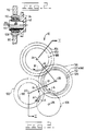
- a countershaft transmission 10 having a lower input shaft 12, an upper output shaft 14, and an intermediately positioned countershaft 16 rotatably supported in a housing or case 18.
- An idler gear support shaft 20 illustrated in Fig. 2 is also releasably secured to the housing 18, and the shafts 12, 14, 16 and 20 respectively have parallel axes 22, 24, 26 and 28 that have an elevational end view relationship as is shown in Fig. 3. It can be noted from Fig. 3 that the idler gear support shaft is located elevationally below the input shaft, and the axes are arranged in a relatively tight or compact quadrangle.
- the housing 18 is generally constructed of two major pieces; namely, a rear main case portion 30 disposed at the left when viewing Fig. 1, and a front cover portion 32 located at the right.
- a front wall 34 of the cover portion integrally defines a stepped bore 36 on the input axis 22, a bore 38 on the output axis 24, a stepped bore 40 on the intermediate axis 26, and a blind bore 42 on the idler gear axis 28 as is shown in Fig. 2.
- the front end of the idler gear support shaft 20 is seated in the bore 42 and is releasably secured to the front wall by one or more threaded fasteners or bolts 44, one of which is illustrated.
- a rear wall 46 of the main case portion 30 integrally defines a stepped bore 48 on the input axis 22, and blind cylindrically-shaped stepped pockets 50 and 52 on the output axis 24 and on the intermediate axis 26, respectively.
- the housing is generally cylindrical in shape, and a peripherally extending mounting flange 54 is integrally formed on the main case portion.
- a plurality of threaded fasteners or bolts 56 extend therethrough in use to releasably secure the transmission to an annular vehicle frame member 58.
- the frame member defines a cylindrical bore 59 therethrough and the countershaft transmission 10 is pilotably received in that bore.
- Another plurality of threaded fasteners or bolts 60 secure the main case portion 30 and the cover portion 32 positively together and serve to define an internal chamber 62.
- Input shaft 12 has a front spline portion 64 which is preferably driven by an engine and a hydrodynamic torque converter arranged in series in the usual way, although not illustrated.
- the front end of the input shaft is rotatably supported in the front wall 34 by a roller bearing assembly 66 seated in the stepped bore 36, and the rear end is rotatably supported in the rear wall 46 by another roller bearing assembly 68 seated in the stepped bore 48.
- the input shaft has a rear spline portion 70 that can be coupled to a power take-off (PTO) shaft, not shown, for driving auxiliary equipment on the vehicle such as a winch or the like.
- a cover plate 72 can be releasably secured to the main case portion 30 when the PTO shaft is not utilized.
- annular web 74 is integrally formed on the input shaft 12 centrally thereof, and an internally splined front drum 76 and an internally splined rear drum 77 are integrally secured to the web as by welding or the like.
- the drums 76 and 77 respectively form the driving members of first directional clutch means 78 and second directional clutch means 79.
- the first and second directional clutch means respectively include a forward clutch 80 and a reverse clutch 82 of the usual interleaved multiple plate and disc type.
- the forward clutch 80 includes an annular actuating piston 84 selectively movable to the right when viewing Fig.
- a second gear 100 and an integrally associated externally splined hub 102 are also freely rotatably mounted on the input shaft 12 by a sleeve bearing or needle bearing assembly 104. Movement of an actuating piston 106 of the reverse clutch 82 to the left when viewing Fig. 1 couples the second gear 100 and hub 102 to the input shaft.
- actuation of the forward and reverse clutches 80 and 82 are effective to provide drive to either of the gears 90 and 100, with it being understood that the designation of clutches 80 and 82 as being forward and reverse is arbitrary and could be just as easily considered as being reverse and forward respectively.
- an idler third gear 108 is freely rotatably mounted on the stationary stub-type support shaft 20 through a pair of opposed tapered roller bearing assemblies 110 in a conventional manner.
- the idler third gear is intermeshingly engaged directly with the first gear 90 on the input shaft 12 and a fourth gear 112 located on the countershaft 16.
- the countershaft 16 is supported at its front end in a roller bearing assembly 114 seated in the stepped bore 40 of the front wall 34, and at its rear end in a roller bearing assembly 116 seated in the stepped pocket 52 in the rear wall 46.
- the fourth gear 112 is connected to continually rotate with the countershaft through a front spline joint 118, and a fifth gear 120 which is intermeshed with the second gear 100 is similarly connected for conjoint rotation therewith through a rearwardly disposed spline joint 122.
- a sixth gear 128 and associated hub 130 are mounted for free rotation on the front end of the countershaft through a sleeve bearing or needle bearing assembly 132, and are selectively coupled for joint rotation therewith by speed clutch means 133 including, specifically, a first speed clutch 134.
- a seventh gear 136 and an associated hub 138 are freely rotatably mounted on the rear end of the countershaft through another sleeve bearing or needle bearing assembly 140.
- the speed clutch means 133 includes a third speed clutch 142 for selectively coupling the seventh gear 136 directly to the countershaft.
- a front drum 143 and a rear drum 144 are integrally connected to a centrally located countershaft web 145, and these drums form a portion of the back-to-back first and third speed clutches 134,142 in a manner similar to the construction of the back-to-back forward and reverse clutches 80 and 82.
- a ring-like eighth gear 146 is integrally formed on the periphery of the web 145 for conjoint rotation with the countershaft.
- the upper output shaft 14 is indirectly rotatably supported at its front end by an output bevel pinion gear 150 through an intermediate spline joint 152.
- An annular adapter plate 154 is releasably secured to the front wall 34 at the bore 38, and a tapered roller bearing assembly 156 is seated within the adapter plate to provide support for one end of the pinion gear.
- Another tapered roller bearing assembly 158 is seated within a blind bore 160 defined in the rear surface of the front wall 34 to provide support for the other end of the output pinion gear. It is to be appreciated that one end of the output shaft could be rotatably supported in the front wall 34 in any number of ways without departing from the spirit of the present invention.
- the other end of the output shaft is supported by a roller bearing assembly 162 seated in the stepped pocket 50 in the rear wall 46.
- a ninth gear 164 forms an integral part of the front portion of the output shaft 14, and a tenth gear 168 is releasably connected to the output shaft through a rear spline joint 170.
- An eleventh gear 172 and externally splined hub 174 are freely rotatably mounted on the output shaft via a sleeve bearing or needle bearing assembly 176.
- the eleventh gear and hub are selectively connected to the output shaft by a second speed clutch 178 of the speed clutch means 133.
- the sixth and ninth gears 128 and 164 are continually intermeshed, the seventh and tenth gears 136 and 168 are continually intermeshed, and the eighth and eleventh gears 146 and 172 are continually intermeshed respectively.
- the directional clutches 80 and 82, the gear pair 100-120, and the gear train 90-108-112 define a forward and reverse mechanism 179 that is serially arranged ahead of the speed clutches 134,142 and 178, and the gear pairs 128-164, 136-168 and 146-172 that define a three-speed mechanism 181.
- the first, second and third speed clutches 134, 178 and 142 are similar in construction to the directional clutches 80 and 82 and therefore need not be described in detail. However, many of the individual members thereof are advantageously the same size for improved parts commonality. For example, all of the speed clutches use the same size clutch plates, discs and pistons. The directional clutches use a common larger diameter size of these plates, discs and pistons.
- the input shaft 12 is driven by the engine and torque converter of the vehicle in a clockwise direction when viewing along input axis 22 in Fig. 3.
- the operator so controls the vehicle that the forward clutch 80 and the first speed clutch 134 are hydraulically actuated so as to clamp the interleaved plates and discs thereof together.
- This connects the first gear 90 to the input shaft 12 and the sixth gear 128 to the countershaft 16.
- the output shaft 14 is driven at a relatively low speed by way of the three gear chain 90-108-112 and the gear pair 128-164.
- the intermeshing gears 90-108-112 form the only three gear train in the instant transmission.
- the output shaft 14 is driven in a counterclockwise direction.
- the second speed clutch 178 is disengaged and the third speed clutch 142 is engaged to make an upshift from the second forward to the third forward speed condition. This further reduces the speed reduction ratio and speeds up the output shaft 14 via the three gear chain 90-108-112 and the gear pair 136-168.
- Second speed reverse is achieved by engaging clutches 82 and 178 so that the torque transmitting path is by way of gear pairs 100-120 and 146-172.
- Third speed reverse is obtained by engaging clutches 82 and 142, and driving the output shaft 14 via gear pairs 100-120 and 136-168.
- a feature of the countershaft transmission 10 is that the speed gear pair 128-164 defines a first plane 180 centrally thereof normal to the shaft axes 22, 24 and 26, and the speed gear pair 136-168 defines a second plane 182 centrally thereof and parallel to the first plane 180, and all five clutches 80, 82, 134, 178 and 142 are axially located substantially between these two planes.
- the directional three gear train 90-108-112 is located axially exteriorly of the planes 180,182 at the front end thereof, and the directional gear pair 100-120 is located axially exteriorly of the planes at the rear end thereof.
- the gear pair 146-172 is located axially between these planes. This results in an extremely axially compact transmission.
- the back-to-back clutches 80-82 and 134-142 are closely radially spaced and longitudinally aligned, and the second speed clutch 178 is closely radially spaced and longitudinally aligned therewith.
- the back-to-back clutch pairs 80-82 and 134-142 and the clutch 178 form a compact triangle when viewed along the axes as may be appreciated by reference to the gear locations illustrated in Fig. 3.
- the construction of the two-piece housing 18 and its bores 36, 38, 40, 42 and 48 and pockets 50 and 52 allows the convenient assembly of the shafts 12, 14, 16 and 20 and associated members assembled thereon substantially simultaneously, and the construction of the housing provides a plurality of fluid passages for directing pressurized fluid to the clutch actuating pistons and for directing lubricating and cooling fluid to the clutches and bearings through the shafts 12, 14 and 16, although this is not illustrated in full detail.
- One of the major features of the countershaft transmission 10 is that a speed reduction ratio change can be made to any of the speed gear pairs 128-164, 136-168 and 146-172, which comprises a three-speed mechanism when considered with the associated clutches, without effecting the speed reduction ratio of the directional pair of gears 100-120 or the three-gear train 90-108-112 which comprises a directional mechanism when considered with the associated clutches.
- the countershaft transmission 10 provides flexibility of design between the speeds and between forward and reverse so that it can be conveniently modified for a variety of vehicular applications without changing the location of the axes 22, 24, 26 and 28 or modifying the housing 18.
- the construction of the aforementioned Komatsu Model WA300-1 for example, is not sufficiently compact and is much more restricted in achieving the combination of the overall ratio and the desired step between forward and reverse.
- the constant mesh countershaft transmission 10 is simple and rugged in its construction, and is very compact. It features the forward and reverse mechanism 179 ahead of, and independent of, the three-speed mechanism 181, with an elevationally lower input shaft 12 and an elevationally higher output shaft 14.
- the three-gear train 90-108-112 provides the speed reduction capability necessary to obtain a relatively large speed ratio between the forward and reverse speeds, for example above 20%, than is possible with many other designs. This provides high drawbar capability in the forward gears and high travel speeds in the reverse gears which is particularly desirable for track-type tractor use.
Applications Claiming Priority (2)
| Application Number | Priority Date | Filing Date | Title |
|---|---|---|---|
| US07/110,914 US4846009A (en) | 1987-10-21 | 1987-10-21 | Countershaft transmission |
| US110914 | 1987-10-21 |
Publications (3)
| Publication Number | Publication Date |
|---|---|
| EP0339049A1 EP0339049A1 (en) | 1989-11-02 |
| EP0339049A4 EP0339049A4 (en) | 1990-02-20 |
| EP0339049B1 true EP0339049B1 (en) | 1993-11-10 |
Family
ID=22335619
Family Applications (1)
| Application Number | Title | Priority Date | Filing Date |
|---|---|---|---|
| EP88901512A Expired - Lifetime EP0339049B1 (en) | 1987-10-21 | 1987-12-15 | Countershaft transmission |
Country Status (9)
| Country | Link |
|---|---|
| US (1) | US4846009A (ja) |
| EP (1) | EP0339049B1 (ja) |
| JP (1) | JPH02501845A (ja) |
| CN (1) | CN1016211B (ja) |
| AU (1) | AU1291088A (ja) |
| BR (1) | BR8707947A (ja) |
| CA (1) | CA1302736C (ja) |
| DE (1) | DE3788136D1 (ja) |
| WO (1) | WO1989003945A1 (ja) |
Families Citing this family (36)
| Publication number | Priority date | Publication date | Assignee | Title |
|---|---|---|---|---|
| US5079965A (en) * | 1989-07-14 | 1992-01-14 | Zahnradfabrik Friedrichshafen Ag | Gearbox |
| SE467574B (sv) * | 1990-12-10 | 1992-08-10 | Volvo Ab | Stegvaexlad automatvaexellaada foer motorfordon |
| DE4341567C2 (de) * | 1993-12-07 | 2000-11-02 | Heidelberger Druckmasch Ag | Verfahren und Vorrichtung zum reversiblen Beschreiben eines Druckformträgers innerhalb einer Offsetdruckmaschine |
| US5557978A (en) * | 1995-03-07 | 1996-09-24 | Deere & Company | Countershaft power transmission |
| US5901605A (en) * | 1997-04-14 | 1999-05-11 | Sauer Inc. | Power takeoff assembly and method of converting same to include selectively controlled multiple power takeoff shafts |
| US6260682B1 (en) * | 1999-11-29 | 2001-07-17 | Dana Corporation | Power take-off unit having two-piece output gear assembly |
| JP3294230B2 (ja) * | 2000-02-22 | 2002-06-24 | 株式会社日立製作所 | 自動車用制御装置,自動車の制御方法,変速機 |
| JP2001234451A (ja) | 2000-02-22 | 2001-08-31 | Tsudakoma Corp | 織機における耳形成装置の駆動方法及び装置 |
| US6513399B2 (en) | 2000-12-28 | 2003-02-04 | Case Corp. | Dual power flow counter shaft transmission |
| BR0207834A (pt) * | 2001-02-23 | 2004-06-22 | Luk Lamellen Und Kupp Lungsbau | Câmbio |
| US6620070B2 (en) * | 2001-08-10 | 2003-09-16 | Caterpillar Inc | Multi-speed transmission |
| US7521168B2 (en) | 2002-02-13 | 2009-04-21 | Fujifilm Corporation | Resist composition for electron beam, EUV or X-ray |
| US6939662B2 (en) | 2002-05-31 | 2005-09-06 | Fuji Photo Film Co., Ltd. | Positive-working resist composition |
| ATE398298T1 (de) | 2004-07-20 | 2008-07-15 | Fujifilm Corp | Bilderzeugendes material |
| US7017887B1 (en) * | 2004-11-22 | 2006-03-28 | Campbell Hausfeld/Scott Fetzer Company | Winch for boat trailer |
| JP4439409B2 (ja) | 2005-02-02 | 2010-03-24 | 富士フイルム株式会社 | レジスト組成物及びそれを用いたパターン形成方法 |
| US20060204732A1 (en) | 2005-03-08 | 2006-09-14 | Fuji Photo Film Co., Ltd. | Ink composition, inkjet recording method, printed material, method of producing planographic printing plate, and planographic printing plate |
| JP2007051193A (ja) | 2005-08-17 | 2007-03-01 | Fujifilm Corp | インク組成物、インクジェット記録方法、印刷物、平版印刷版の製造方法、及び、平版印刷版 |
| ATE410460T1 (de) | 2005-08-23 | 2008-10-15 | Fujifilm Corp | Härtbare tinte enthaltend modifiziertes oxetan |
| JP4757574B2 (ja) | 2005-09-07 | 2011-08-24 | 富士フイルム株式会社 | インク組成物、インクジェット記録方法、印刷物、平版印刷版の製造方法、及び、平版印刷版 |
| EP2103639A1 (en) | 2005-11-04 | 2009-09-23 | Fujifilm Corporation | Curable polycyclic epoxy composition, ink composition and inkjet recording method therewith |
| EP1829684B1 (en) | 2006-03-03 | 2011-01-26 | FUJIFILM Corporation | Curable composition, ink composition, inkjet-recording method, and planographic printing plate |
| JP2008189776A (ja) | 2007-02-02 | 2008-08-21 | Fujifilm Corp | 活性放射線硬化型重合性組成物、インク組成物、インクジェット記録方法、印刷物、平版印刷版の作製方法、及び平版印刷版 |
| US20080271940A1 (en) * | 2007-05-04 | 2008-11-06 | De Craemer Thomas M M | Transmission system for a vehicle |
| JP5111039B2 (ja) | 2007-09-27 | 2012-12-26 | 富士フイルム株式会社 | 重合性化合物、重合開始剤、および染料を含有する光硬化性組成物 |
| US8240838B2 (en) | 2007-11-29 | 2012-08-14 | Fujifilm Corporation | Ink composition for inkjet recording, inkjet recording method, and printed material |
| JP5106285B2 (ja) | 2008-07-16 | 2012-12-26 | 富士フイルム株式会社 | 光硬化性組成物、インク組成物、及び該インク組成物を用いたインクジェット記録方法 |
| JP5383133B2 (ja) | 2008-09-19 | 2014-01-08 | 富士フイルム株式会社 | インク組成物、インクジェット記録方法及び印刷物成形体の製造方法 |
| ATE541905T1 (de) | 2008-09-26 | 2012-02-15 | Fujifilm Corp | Tintenzusammensetzung und tintenaufzeichnungsverfahren |
| JP5461809B2 (ja) | 2008-09-29 | 2014-04-02 | 富士フイルム株式会社 | インク組成物、及び、インクジェット記録方法 |
| DE102012009310A1 (de) * | 2012-05-10 | 2013-11-14 | Bomag Gmbh | Baumaschine zum Bearbeiten einer Fahrbahnoberfläche |
| WO2015149874A1 (de) * | 2014-04-04 | 2015-10-08 | Gkn Driveline International Gmbh | Antriebsanordnung für ein kraftfahrzeug |
| DE102015206877A1 (de) * | 2015-04-16 | 2016-10-20 | Zf Friedrichshafen Ag | Splittergetriebe, Gesamtgetriebe und landwirtschaftliche Arbeitsmaschine |
| CN106090145A (zh) * | 2016-08-04 | 2016-11-09 | 四川川龙拖拉机制造有限公司 | 一种山地拖拉机换挡装置 |
| US10935109B2 (en) | 2017-06-22 | 2021-03-02 | Kubota Corporation | Work vehicle transmission and work vehicle having the same |
| JP6762270B2 (ja) * | 2017-06-22 | 2020-09-30 | 株式会社クボタ | 作業車用トランスミッション及びこれを備えた作業車 |
Family Cites Families (13)
| Publication number | Priority date | Publication date | Assignee | Title |
|---|---|---|---|---|
| US2953942A (en) * | 1959-04-27 | 1960-09-27 | Eimco Corp | Transmission |
| US3318167A (en) * | 1964-12-23 | 1967-05-09 | Clark Equipment Co | Tri-shaft transmission |
| US3425293A (en) * | 1967-02-13 | 1969-02-04 | Twin Disc Inc | Power transmission and control system therefor |
| US3858455A (en) * | 1973-08-27 | 1975-01-07 | Clark Equipment Co | Transmissions |
| US4145935A (en) * | 1977-08-22 | 1979-03-27 | Zahnradfabrik Friedrichshafen Ag | Multispeed reversible transmission shiftable under load |
| DE2800267C2 (de) * | 1978-01-04 | 1984-03-29 | J.M. Voith Gmbh, 7920 Heidenheim | Viergängiges Schaltgetriebe |
| IT1119624B (it) * | 1979-12-18 | 1986-03-10 | Fiat Allis Macch Movi | Cambio di velocita del tipo con comando idraulico per l'innesto delle marce e contralbero |
| US4523655A (en) * | 1982-11-26 | 1985-06-18 | Deere & Company | Vehicle frame transmission mounting assembly |
| US4589294A (en) * | 1982-11-26 | 1986-05-20 | Keenan Thomas F | Vehicle transmission with a plurality of forward and reverse speeds |
| US4589295A (en) * | 1984-01-30 | 1986-05-20 | Champion Road Machinery Limited | Eight speed drop box transmission |
| US4570503A (en) * | 1984-09-17 | 1986-02-18 | Caterpillar Tractor Co. | Countershaft transmission |
| US4627302A (en) * | 1985-09-26 | 1986-12-09 | Caterpillar Inc. | Countershaft transmission |
| US4726246A (en) * | 1986-10-01 | 1988-02-23 | Caterpillar Inc. | Countershaft transmission having two forward and two reverse speeds |
-
1987
- 1987-10-21 US US07/110,914 patent/US4846009A/en not_active Expired - Lifetime
- 1987-12-15 AU AU12910/88A patent/AU1291088A/en not_active Abandoned
- 1987-12-15 EP EP88901512A patent/EP0339049B1/en not_active Expired - Lifetime
- 1987-12-15 BR BR8707947A patent/BR8707947A/pt unknown
- 1987-12-15 WO PCT/US1987/003308 patent/WO1989003945A1/en active IP Right Grant
- 1987-12-15 DE DE88901512T patent/DE3788136D1/de not_active Expired - Lifetime
- 1987-12-15 JP JP63501692A patent/JPH02501845A/ja active Pending
-
1988
- 1988-10-18 CA CA000580464A patent/CA1302736C/en not_active Expired - Lifetime
- 1988-10-19 CN CN88107316.4A patent/CN1016211B/zh not_active Expired
Also Published As
| Publication number | Publication date |
|---|---|
| CN1016211B (zh) | 1992-04-08 |
| DE3788136D1 (de) | 1993-12-16 |
| EP0339049A1 (en) | 1989-11-02 |
| US4846009A (en) | 1989-07-11 |
| AU1291088A (en) | 1989-05-23 |
| JPH02501845A (ja) | 1990-06-21 |
| EP0339049A4 (en) | 1990-02-20 |
| WO1989003945A1 (en) | 1989-05-05 |
| CA1302736C (en) | 1992-06-09 |
| CN1032698A (zh) | 1989-05-03 |
| BR8707947A (pt) | 1990-02-13 |
Similar Documents
| Publication | Publication Date | Title |
|---|---|---|
| EP0339049B1 (en) | Countershaft transmission | |
| EP0214125B1 (en) | Countershaft transmission | |
| US4531428A (en) | Planetary transmission | |
| US4420992A (en) | Planetary transmission | |
| US4676116A (en) | Countershaft transmission | |
| EP0343173B1 (en) | Countershaft transmission | |
| US4660425A (en) | Countershaft transmission auxiliary drive mechanism | |
| EP0187750B1 (en) | Countershaft transmission | |
| US4446758A (en) | Planetary transmission | |
| US4282775A (en) | Transmission having a two-speed planetary gear set | |
| US4726246A (en) | Countershaft transmission having two forward and two reverse speeds | |
| CA1259825A (en) | Countershaft transmission | |
| US4658673A (en) | Planetary transmission | |
| EP0083337B1 (en) | Planetary transmission | |
| IL45413A (en) | Mechanical power transmission | |
| CA1172064A (en) | Planetary transmission | |
| CA1242339A (en) | Countershaft transmission | |
| CA1231556A (en) | Countershaft transmission | |
| GB1605068A (en) | Transmission for a frameless tractor |
Legal Events
| Date | Code | Title | Description |
|---|---|---|---|
| PUAI | Public reference made under article 153(3) epc to a published international application that has entered the european phase |
Free format text: ORIGINAL CODE: 0009012 |
|
| 17P | Request for examination filed |
Effective date: 19890512 |
|
| AK | Designated contracting states |
Kind code of ref document: A1 Designated state(s): BE DE FR GB IT |
|
| A4 | Supplementary search report drawn up and despatched |
Effective date: 19900220 |
|
| 17Q | First examination report despatched |
Effective date: 19920305 |
|
| GRAA | (expected) grant |
Free format text: ORIGINAL CODE: 0009210 |
|
| AK | Designated contracting states |
Kind code of ref document: B1 Designated state(s): BE DE FR GB IT |
|
| PG25 | Lapsed in a contracting state [announced via postgrant information from national office to epo] |
Ref country code: IT Free format text: LAPSE BECAUSE OF FAILURE TO SUBMIT A TRANSLATION OF THE DESCRIPTION OR TO PAY THE FEE WITHIN THE PRE;WARNING: LAPSES OF ITALIAN PATENTS WITH EFFECTIVE DATE BEFORE 2007 MAY HAVE OCCURRED AT ANY TIME BEFORE 2007. THE CORRECT EFFECTIVE DATE MAY BE DIFFERENT FROM THE ONE RECORDED.SCRIBED TIME-LIMIT Effective date: 19931110 Ref country code: BE Effective date: 19931110 Ref country code: DE Effective date: 19931110 Ref country code: FR Effective date: 19931110 |
|
| REF | Corresponds to: |
Ref document number: 3788136 Country of ref document: DE Date of ref document: 19931216 |
|
| PG25 | Lapsed in a contracting state [announced via postgrant information from national office to epo] |
Ref country code: GB Effective date: 19940210 |
|
| EN | Fr: translation not filed | ||
| PLBE | No opposition filed within time limit |
Free format text: ORIGINAL CODE: 0009261 |
|
| STAA | Information on the status of an ep patent application or granted ep patent |
Free format text: STATUS: NO OPPOSITION FILED WITHIN TIME LIMIT |
|
| GBPC | Gb: european patent ceased through non-payment of renewal fee |
Effective date: 19940210 |
|
| 26N | No opposition filed |