EP0338882B1 - Moteur à allumage par compression comportant une préchambre dont le canal de transfert est rectiligne et incliné - Google Patents
Moteur à allumage par compression comportant une préchambre dont le canal de transfert est rectiligne et incliné Download PDFInfo
- Publication number
- EP0338882B1 EP0338882B1 EP89400902A EP89400902A EP0338882B1 EP 0338882 B1 EP0338882 B1 EP 0338882B1 EP 89400902 A EP89400902 A EP 89400902A EP 89400902 A EP89400902 A EP 89400902A EP 0338882 B1 EP0338882 B1 EP 0338882B1
- Authority
- EP
- European Patent Office
- Prior art keywords
- prechamber
- transfer channel
- axis
- symmetry
- plane
- Prior art date
- Legal status (The legal status is an assumption and is not a legal conclusion. Google has not performed a legal analysis and makes no representation as to the accuracy of the status listed.)
- Expired - Lifetime
Links
- 238000002347 injection Methods 0.000 claims 1
- 239000007924 injection Substances 0.000 claims 1
- 239000007789 gas Substances 0.000 description 10
- 241000219793 Trifolium Species 0.000 description 7
- 238000003754 machining Methods 0.000 description 5
- 238000002485 combustion reaction Methods 0.000 description 3
- 239000000446 fuel Substances 0.000 description 3
- 230000006835 compression Effects 0.000 description 2
- 238000007906 compression Methods 0.000 description 2
- 239000000779 smoke Substances 0.000 description 2
- 239000000567 combustion gas Substances 0.000 description 1
- 238000006073 displacement reaction Methods 0.000 description 1
- 230000002349 favourable effect Effects 0.000 description 1
- 239000012530 fluid Substances 0.000 description 1
- 229930195733 hydrocarbon Natural products 0.000 description 1
- 150000002430 hydrocarbons Chemical class 0.000 description 1
- 238000004519 manufacturing process Methods 0.000 description 1
- 239000000203 mixture Substances 0.000 description 1
- 230000035515 penetration Effects 0.000 description 1
Images


Classifications
-
- F—MECHANICAL ENGINEERING; LIGHTING; HEATING; WEAPONS; BLASTING
- F02—COMBUSTION ENGINES; HOT-GAS OR COMBUSTION-PRODUCT ENGINE PLANTS
- F02B—INTERNAL-COMBUSTION PISTON ENGINES; COMBUSTION ENGINES IN GENERAL
- F02B19/00—Engines characterised by precombustion chambers
- F02B19/14—Engines characterised by precombustion chambers with compression ignition
-
- F—MECHANICAL ENGINEERING; LIGHTING; HEATING; WEAPONS; BLASTING
- F02—COMBUSTION ENGINES; HOT-GAS OR COMBUSTION-PRODUCT ENGINE PLANTS
- F02B—INTERNAL-COMBUSTION PISTON ENGINES; COMBUSTION ENGINES IN GENERAL
- F02B3/00—Engines characterised by air compression and subsequent fuel addition
- F02B3/06—Engines characterised by air compression and subsequent fuel addition with compression ignition
-
- F—MECHANICAL ENGINEERING; LIGHTING; HEATING; WEAPONS; BLASTING
- F02—COMBUSTION ENGINES; HOT-GAS OR COMBUSTION-PRODUCT ENGINE PLANTS
- F02P—IGNITION, OTHER THAN COMPRESSION IGNITION, FOR INTERNAL-COMBUSTION ENGINES; TESTING OF IGNITION TIMING IN COMPRESSION-IGNITION ENGINES
- F02P13/00—Sparking plugs structurally combined with other parts of internal-combustion engines
-
- Y—GENERAL TAGGING OF NEW TECHNOLOGICAL DEVELOPMENTS; GENERAL TAGGING OF CROSS-SECTIONAL TECHNOLOGIES SPANNING OVER SEVERAL SECTIONS OF THE IPC; TECHNICAL SUBJECTS COVERED BY FORMER USPC CROSS-REFERENCE ART COLLECTIONS [XRACs] AND DIGESTS
- Y02—TECHNOLOGIES OR APPLICATIONS FOR MITIGATION OR ADAPTATION AGAINST CLIMATE CHANGE
- Y02T—CLIMATE CHANGE MITIGATION TECHNOLOGIES RELATED TO TRANSPORTATION
- Y02T10/00—Road transport of goods or passengers
- Y02T10/10—Internal combustion engine [ICE] based vehicles
- Y02T10/12—Improving ICE efficiencies
Definitions
- the invention relates to a compression ignition engine comprising a prechamber whose transfer channel is rectilinear and inclined relative to the plane of symmetry of the prechamber.
- Diesel engines comprising, associated with each of their cylinders, a turbulence prechamber, for example a Ricardo type prechamber.
- the engine comprises a cylinder block above which is placed a cylinder head inside which are arranged the pre-chambers of turbulence of approximately spherical shape.
- Each of the pre-chambers is connected by a channel to a main chamber which is delimited, inside the corresponding cylinder, by the head of the piston and by an adjacent part of the cylinder head.
- the transfer channel preferably has a tangential arrangement with respect to the prechamber and puts the prechamber into communication with the main chamber.
- an injector generally disposed opposite the mouth of the transfer channel and a spark plug which makes it possible to preheat and ignite the fuel mixture when the engine is cold started.
- the prechamber has a plane of symmetry passing through the axis of the corresponding cylinder and the spark plug and the injector are arranged so that their axes of symmetry are located in this plane.
- the longitudinal axis of the transfer channel which is generally rectilinear is arranged in the plane of symmetry of the prechamber.
- This arrangement corresponds to an optimum, in particular with regard to the relative position of the injector and of the spark plug, which makes it possible to obtain satisfactory cold start conditions.
- the transfer channel opens out under the spark plug, so that this results in disturbances in the flow of gases inside the prechamber.
- the spark plug constitutes a very significant aerodynamic obstacle which disturbs the speed field in the vicinity of the injector. Combustion is degraded and this results in an increase in emissions of smoke and unburnt hydrocarbons.
- the fluid moving in the prechamber must be animated by a swirling movement around an axis passing through the center of the chamber cavity.
- GB-A-625,946 also discloses a compression-ignition engine comprising, for each of the cylinders, an insert inside the cylinder head in which is machined, for each of the engine's cylinders, part of the prechamber and a straight transfer channel.
- the piston of the cylinder is machined at its upper part to form a cavity in the extension of the transfer channel.
- the symmetrical arrangement of the transfer channel and the piston cavity have the drawbacks mentioned above.
- the object of the invention is therefore to propose a compression-ignition engine comprising at least one cylinder in which a piston moves and a turbulence prechamber constituted, at least in its lower part, by an insert inside the cylinder head in which is machined a rectilinear transfer channel communicating with the cylinder, the pre-chamber having a plane of symmetry P passing through the axis of the cylinder and comprising a glow plug and an injector whose axes of symmetry are located in the plane of symmetry P of the prechamber, the longitudinal axis of the transfer channel making a non-zero angle ⁇ with the plane of symmetry and the upper part of the piston placed in the cylinder being machined to form a cavity in shape of a clover in the extension of the transfer channel having two substantially circular lobes, this motor having improved performance thanks to the fact that the vortex flow is not disturbed by the presence of the spark plug in the prechamber, without however requiring machining special cylinder head and / or pre-chamber.
- the orientation of the axis of the transfer channel of the prechamber is obtained by a rotation of the insert inside the cylinder head, from its position in which the axis of the rectilinear transfer channel is in the plane of symmetry of the prechamber and that the radii R1, R2 of the two lobes of the cavity of the piston are unequal.
- Figure 1 is a sectional view through a vertical plane of a portion of a conventional type diesel engine having a turbulence prechamber.
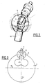
- Figure 2 is a perspective view, broken away, of a prechamber of an engine according to the prior art.
- Figure 3 is a schematic top view of a prechamber according to the prior art.
- Figure 4 is a cutaway perspective view of a turbulence prechamber according to the invention.
- Figure 5 is a schematic top view of the prechamber according to the invention.
- FIG. 1 we see a part of the cylinder block 1 and the cylinder head 2 of a compression ignition engine.
- the cylinder block 1 comprises cylinders such as 3 in each of which moves a piston 4.
- the cylinder head 2 is machined above each of the cylinders 3, so as to delimit a turbulence pre-chamber 5 comprising a fuel injector 6 and a glow plug 7.
- the prechamber 5 of substantially spherical shape is delimited at its upper part by a hemispherical wall machined inside the cylinder head 2.
- the lower part of the prechamber 5 is machined inside an attached part 9 and fixed to the inside a correspondingly shaped housing machined in the cylinder head 2.
- a transfer channel 10 in a direction substantially tangential to the wall of the prechamber 5 is machined inside the part 9 and places the upper part of the cylinder 3 and the lower part of the prechamber 5 in communication.
- the axis 11 of the injector 6, the axis 12 of the spark plug 7 and the axis 13 of the channel 10 are all located in the same plane which is a plane of symmetry of the pre-chamber 5 and of the cylinder 3, it that is to say a plane of symmetry of the prechamber 5 passing through the axis of the cylinder 3.
- the upper surface of the piston 4 is machined to form a cavity 16 in the shape of a shallow clover.
- This cavity delimits the main chamber with the adjacent surface of the cylinder head, in the high position of the piston 4.
- the particular shape given to this cavity located in the extension of the transfer channel 10 ensures optimal distribution of the gases in the chamber main, relative to piston 4.
- FIGS. 4 and 5 show the prechamber 20 of an engine according to the invention, the general structure of which is identical to the structure of the engine according to the prior art shown in FIG. 1.
- the pre-chamber 20 has a generally spherical shape and includes a glow plug 21 the projecting end of which inside the chamber 20 has an axis 23 situated in the plane of symmetry of the pre-chamber 20 of trace 24 on the plane of FIG. 5.
- This plane of symmetry which is perpendicular to the axis of crankshaft 25 of the engine passes through the axis of the cylinder with which the prechamber 20 is associated and in which the piston 26 moves.
- the prechamber 20 also includes an injector which has not been shown in FIGS. 4 and 5, for reasons of clarity.
- This injector the shape of which is identical to the injector 6 shown in FIG. 1, opens into the upper part of the prechamber 20 and has an axis located in the plane of symmetry of trace 24.
- the engine according to the invention therefore meets the ideal conditions with regard to the respective positions of the spark plug and the injector.
- the transfer channel 30 is inclined with respect to the plane of symmetry and forms an angle ⁇ visible with this plane in FIG. 5.
- This arrangement makes it possible to direct the gases entering the prechamber 20 laterally so as to cause these gases to circulate in a swirling movement around the axis 23 of the spark plug 21 (arrows 31 in FIG. 4). The circulation of gases in the prechamber 20 is therefore not disturbed by the projecting part of the spark plug 21.
- the clover-shaped cavity 36 is asymmetrical and comprises two substantially circular lobes having radii R1 and R2 different.
- the connection point 34 of the two clover lobes 36 is offset by a distance a relative to the axis 32 of the conduit 30.
- This arrangement and this shape given to the clover 36 make it possible to re-center the flow of the gases during combustion, relative to the piston 26. This gives homogeneous combustion and a good distribution of the combustion gases in the prechamber and in the main chamber. , despite the inclined position of the transfer channel 30.
- the inclined arrangement according to the invention of the transfer channel 30 can be obtained, in the case where the prechamber is constituted, in its lower part, by an attached part 9, as shown in Figure 1, by a simple rotation of a desired angle of this symmetrical part of revolution, inside its housing in the cylinder head, from its position shown in Figure 1 where the axis of the transfer channel is in the plane of symmetry from the prechamber.
- the production of the improved motor according to the invention therefore does not require the machining of a special part but simply a different orientation of the part delimiting the prechamber, in its housing.
- This rotation of the insert from its position shown in Figure 1, will preferably be between 10 and 20 °.
- the piston 26 must be machined to produce on its upper part a cavity in the shape of an asymmetrical clover such as the cavity 36 shown in FIG. 5.
- this clover-shaped cavity will include two lobes whose radii R1 and R2 are such that the ratio R1 / R2 is between 1 and 2.
- the offset a from the connection point 34 of the two lobes will generally be between 0.5 and 10 mm.
- the invention makes it possible to increase the efficiency of the engine and to reduce the emissions of smoke and unburnt gases while preserving a good quality of the cold start.
- the results are obtained by keeping the axis of the spark plug and the injector in the plane of symmetry of the prechamber and by circulating the gases around the axis of the spark plug. These results can be obtained by a simple adjustment in orientation of the part constituting the lower part of the prechamber, inside the cylinder head.
- the transfer channel can be produced directly by machining the cylinder head in a direction inclined relative to the plane of symmetry of the prechamber.
- the inclination of the transfer channel can be variable depending on the geometry of the turbulence prechamber and the position of the spark plug.
- the shape of the clover and the relative dimensions of its lobes may be variable depending on the inclination ⁇ of the axis of the transfer channel.
- the dimensions of the clover depend on the dimensional characteristics of the engine and in particular on its displacement.
- the invention applies to any compression-ignition engine comprising at least one cylinder with which there is associated a turbulence prechamber.
Landscapes
- Engineering & Computer Science (AREA)
- Chemical & Material Sciences (AREA)
- Combustion & Propulsion (AREA)
- Mechanical Engineering (AREA)
- General Engineering & Computer Science (AREA)
- Combustion Methods Of Internal-Combustion Engines (AREA)
Description
- L'invention concerne un moteur à allumage par compression comportant une préchambre dont le canal de transfert est rectiligne et incliné par rapport au plan de symétrie de la préchambre.
- On connaît des moteurs Diésel comportant, associée à chacun de leurs cylindres, une préchambre de turbulence, par exemple une préchambre du type Ricardo. Le moteur comporte un bloc-cylindre au-dessus duquel est placée une culasse à l'intérieur de laquelle sont disposées les préchambres de turbulence de forme approximativement sphérique. Chacune des préchambres est reliée par un canal à une chambre principale qui est délimitée, à l'intérieur du cylindre correspondant, par la tête du piston et par une partie adjacente de la culasse. Le canal de transfert a de préférence une disposition tangentielle par rapport à la préchambre et met en communication la préchambre avec la chambre principale. Dans la préchambre se trouve placé un injecteur généralement disposé à l'opposé de l'embouchure du canal de transfert et une bougie qui permet d'assurer le préchauffage et l'inflammation du mélange combustible au démarrage à froid du moteur.
- La préchambre comporte un plan de symétrie passant par l'axe du cylindre correspondant et la bougie et l'injecteur sont disposés de façon que leurs axes de symétrie soient situés dans ce plan. De même, l'axe longitudinal du canal de transfert qui est généralement rectiligne est disposé dans le plan de symétrie de la préchambre.
- Cette disposition correspond à un optimum, en particulier en ce qui concerne la position relative de l'injecteur et de la bougie, ce qui permet d'obtenir des conditions de démarrage satisfaisantes à froid.
- Cependant, dans cette disposition, le canal de transfert débouche sous la bougie, si bien qu'il en résulte des perturbations dans l'écoulement des gaz à l'intérieur de la préchambre. La bougie constitue un obstacle aérodynamique très important qui perturbe le champ de vitesse au voisinage de l'injecteur. La combustion s'en trouve dégradée et il en résulte une augmentation des émissions de fumées et d'hydrocarbures imbrûlés.
- Il est bien connu que la qualité du fonctionnement d'un moteur Diésel à préchambre est liée à la manière dont le mélange de l'air comprimé par le piston et du combustible pulvérisé par l'injecteur se fait dans la préchambre et à la manière dont les gaz enflammés passent dans la chambre principale.
- De préférence, le fluide en déplacement dans la préchambre doit être animé d'un mouvement tourbillonnaire autour d'un axe passant par le centre de la cavité de la chambre.
- Cet écoulement tourbillonnaire étant fortement perturbé par la présence de la bougie, il en résulte des performances amoindries du moteur Diésel.
- Différentes solutions ont été proposées pour limiter les inconvénients dus à la présence de la bougie. On a par exemple proposé d'utiliser des bougies dont la position, la section, les dimensions et la pénétration dans la préchambre limitent les perturbations. Ces dispositions ne permettent cependant pas de maintenir des conditions favorables en ce qui concerne la position relative de l'injecteur et de la bougie à l'intérieur de la préchambre.
- On a proposé, dans le brevet FR-A-2.600.718, une préchambre dont l'axe du canal de transfert est une courbe gauche, la bougie saillante dans la préchambre étant disposée par rapport à ce canal de transfert, de manière qu'un courant tourbillonnaire se forme autour de l'axe de la bougie. Un tel dispositif nécessite cependant un usinage complexe de la préchambre, en raison de la forme du canal de transfert.
- On a également proposé, dans le FR-A-1.069.788, un moteur à allumage par compression dont la culasse est usinée pour constituer une préchambre et un canal de transfert qui peut être fortement incliné par rapport à un plan de symétrie de la préchambre. L'usinage de la culasse d'un tel moteur est relativement complexe et l'angle d'inclinaison du canal de transfert ne peut être réglé qu'au moment de l'usinage de la culasse.
- On connaît également par le GB-A-625.946, un moteur à allumage par compression comportant pour chacun des cylindres une pièce rapportée à l'intérieur de la culasse dans laquelle est usinée, pour chacun des cylindres du moteur, une partie de la préchambre et un canal de transfert rectiligne. Le piston du cylindre est usiné à sa partie supérieure pour constituer une cavité dans le prolongement du canal de transfert. La disposition symétrique du canal de transfert et de la cavité du piston présentent les inconvénients mentionnés plus haut.
- Le but de l'invention est donc de proposer un moteur à allumage par compression comportant au moins un cylindre dans lequel se déplace un piston et une préchambre de turbulence constituée, au moins dans sa partie inférieure, par une pièce rapportée à l'intérieur de la culasse dans laquelle est usiné un canal de transfert rectiligne communiquant avec le cylindre, la préchambre présentant un plan de symétrie P passant par l'axe du cylindre et comportant une bougie de préchauffage et un injecteur dont les axes de symétrie sont situés dans le plan de symétrie P de la préchambre, l'axe longitudinal du canal de transfert faisant un angle α non nul avec le plan de symétrie et la partie supérieure du piston disposé dans le cylindre étant usinée pour constituer une cavité en forme de trèfle dans le prolongement du canal de transfert ayant deux lobes sensiblement circulaires, ce moteur présentant des performances améliorées grâce au fait que l'écoulement tourbillonnaire n'est pas perturbé par la présence de la bougie dans la préchambre, sans nécessiter toutefois un usinage spécial de la culasse et/ou de la préchambre.
- Dans ce but, l'orientation de l'axe du canal de transfert de la préchambre est obtenue par une rotation de la pièce rapportée à l'intérieur de la culasse, à partir de sa position dans laquelle l'axe du canal de transfert rectiligne se trouve dans le plan de symétrie de la préchambre et que les rayons R1, R2 des deux lobes de la cavité du piston sont inégaux.
- Afin de bien faire comprendre l'invention, on va maintenant décrire, à titre d'exemple non limitatif, en se référant aux figures jointes en annexe, un mode de réalisation d'un moteur suivant l'invention, comparativement à un moteur suivant l'art antérieur.
- La figure 1 est une vue en coupe par un plan vertical d'une partie d'un moteur Diésel de type classique comportant une préchambre de turbulence.
- La figure 2 est une vue en perspective, avec arrachement, d'une préchambre d'un moteur suivant l'art antérieur.
- La figure 3 est une vue de dessus schématique d'une préchambre suivant l'art antérieur.
- La figure 4 est une vue en perspective avec arrachement, d'une préchambre de turbulence suivant l'invention.
- La figure 5 est une vue de dessus schématique de la préchambre suivant l'invention.
- Sur la figure 1, on voit une partie du bloc-cylindre 1 et de la culasse 2 d'un moteur à allumage par compression. Le bloc-cylindre 1 comporte des cylindres tels que 3 dans chacun desquels se déplace un piston 4. La culasse 2 est usinée au-dessus de chacun des cylindres 3, de façon à délimiter une préchambre de turbulence 5 comportant un injecteur de carburant 6 et une bougie de préchauffage 7.
- La préchambre 5 de forme sensiblement sphérique est délimitée à sa partie supérieure par une paroi hémisphérique usinée à l'intérieur de la culasse 2. La partie inférieure de la préchambre 5 est usinée à l'intérieur d'une pièce 9 rapportée et fixée à l'intérieur d'un logement de forme correspondante usiné dans la culasse 2.
- Un canal de transfert 10 de direction sensiblement tangentielle par rapport à la paroi de la préchambre 5 est usiné à l'intérieur de la pièce 9 et met en communication la partie supérieure du cylindre 3 et la partie inférieure de la préchambre 5.
- L'axe 11 de l'injecteur 6, l'axe 12 de la bougie 7 et l'axe 13 du canal 10 sont tous situés dans un même plan qui est un plan de symétrie de la préchambre 5 et du cylindre 3, c'est-à-dire un plan de symétrie de la préchambre 5 passant par l'axe du cylindre 3.
- Cette disposition idéale de l'injecteur de la bougie et du canal de transfert est également représentée sur les figures 2 et 3 sur lesquelles les éléments correspondant à ceux représentés sur la figure 1 portent les mêmes repères.
- Cette disposition est particulièrement visible sur la figure 3 où l'on a représenté la trace 14 du plan de symétrie sur le plan de figure. Ce plan de symétrie P de trace 14 est perpendiculaire à l'axe 15 du vilebrequin du moteur.
- Comme il est visible sur les figures 1 et 3, la surface supérieure du piston 4 est usinée pour constituer une cavité 16 en forme de trèfle de faible profondeur. Cette cavité délimite la chambre principale avec la surface adjacente de la culasse, dans la position haute du piston 4. La forme particulière donnée à cette cavité située dans le prolongement du canal de transfert 10 permet d'assurer une répartition optimale des gaz dans la chambre principale, par rapport au piston 4.
- Cependant, comme il est visible sur la figure 2, l'air comprimé dans le cylindre 3 par le piston 4 et refoulé dans la préchambre 5 à travers le canal 10 vient heurter l'extrémité de la bougie 7 saillante dans la préchambre 5 (flèches 18). La présence de la bougie perturbe donc l'écoulement des gaz dans la préchambre, ce qui se traduit par des performances amoindries du moteur.
- Sur les figures 4 et 5, on a représenté la préchambre 20 d'un moteur suivant l'invention dont la structure générale est identique à la structure du moteur selon l'art antérieur représenté sur la figure 1.
- La préchambre 20 a une forme globalement sphérique et comporte une bougie de préchauffage 21 dont l'extrémité saillante à l'intérieur de la chambre 20 comporte un axe 23 situé dans le plan de symétrie de la préchambre 20 de trace 24 sur le plan de la figure 5. Ce plan de symétrie qui est perpendiculaire à l'axe de vilebrequin 25 du moteur passe par l'axe du cylindre auquel est associée la préchambre 20 et dans lequel se déplace le piston 26.
- La préchambre 20 comporte également un injecteur qui n'a pas été représenté sur les figures 4 et 5, pour des raisons de clarté. Cet injecteur dont la forme est identique à l'injecteur 6 représenté sur la figure 1 débouche dans la partie supérieure de la préchambre 20 et comporte un axe situé dans le plan de symétrie de trace 24.
- Le moteur suivant l'invention respecte donc les conditions idéales en ce qui concerne les positions respectives de la bougie et de l'injecteur.
- Cependant, le canal de transfert 30 est incliné par rapport au plan de symétrie et fait avec ce plan un angle α visible sur la figure 5.
- Cette disposition permet de diriger les gaz pénétrant dans la préchambre 20 latéralement de façon à faire circuler ces gaz dans un mouvement tourbillonnaire autour de l'axe 23 de la bougie 21 (flèches 31 sur la figure 4). La circulation des gaz dans la préchambre 20 n'est donc pas perturbée par la partie saillante de la bougie 21.
- On voit sur la figure 5 que le piston 26 correspondant à la préchambre 20 est usiné pour constituer une cavité en forme de trèfle 36 située dans le prolongement du canal de transfert 30 dont l'axe 32 fait un angle α avec le plan de symétrie de la pré-chambre 20 dont la trace 24 est visible sur la figure 5.
- La cavité 36 en forme de trèfle est dissymétrique et comporte deux lobes sensiblement circulaires ayant des rayons R1 et R2 différents. De plus, le point de raccordement 34 des deux lobes du trèfle 36 est désaxé d'une distance a par rapport à l'axe 32 du conduit 30.
- Cette disposition et cette forme données au trèfle 36 permettent de recentrer l'écoulement des gaz en cours de combustion, par rapport au piston 26. On obtient ainsi une combustion homogène et une bonne répartition des gaz de combustion dans la préchambre et dans la chambre principale, malgré la position inclinée du canal de transfert 30.
- Il est à remarquer que la disposition inclinée suivant l'invention du canal de transfert 30 peut être obtenue, dans le cas où la préchambre est constituée, dans sa partie inférieure, par une pièce rapportée 9, comme représenté sur la figure 1, par une simple rotation d'un angle voulu de cette pièce symétrique de révolution, à l'intérieur de son logement dans la culasse, à partir de sa position représentée sur la figure 1 où l'axe du canal de transfert se trouve dans le plan de symétrie de la préchambre.
- La réalisation du moteur amélioré suivant l'invention ne nécessite donc pas l'usinage d'une pièce spéciale mais simplement une orientation différente de la pièce délimitant la préchambre, dans son logement.
- Cette rotation de la pièce rapportée, à partir de sa position représentée sur la figure 1, sera de préférence comprise entre 10 et 20°.
- Le piston 26 devra être usiné pour réaliser sur sa partie supérieure une cavité en forme de trèfle dissymétrique telle que la cavité 36 représentée sur la figure 5.
- De manière avantageuse, cette cavité en forme de trèfle comportera deux lobes dont les rayons R1 et R2 sont tels que le rapport R1/R2 soit compris entre 1 et 2. Le désaxage a du point de raccordement 34 des deux lobes sera généralement compris entre 0.5 et 10 mm.
- L'invention permet d'augmenter le rendement du moteur et de réduire les émissions de fumées et de gaz imbrûlés tout en préservant une bonne qualité du démarrage à froid. Les résultats sont obtenus en maintenant l'axe de la bougie et de l'injecteur dans le plan de symétrie de la préchambre et en faisant circuler les gaz autour de l'axe de la bougie. Ces résultats peuvent être obtenus par un simple réglage en orientation de la pièce constituant la partie inférieure de la préchambre, à l'intérieur de la culasse.
- L'invention ne se limite pas aux modes de réalisation qui ont été décrits.
- C'est ainsi qu'on peut réaliser le canal de transfert directement par usinage de la culasse suivant une direction inclinée par rapport au plan de symétrie de la préchambre. L'inclinaison du canal de transfert peut être variable en fonction de la géométrie de la préchambre de turbulence et de la position de la bougie.
- La forme du trèfle et les dimensions relatives de ses lobes pourront être variables en fonction de l'inclinaison α de l'axe du canal de transfert.
- Les dimensions du trèfle quant à elles dépendent des caractéristiques dimensionnelles du moteur et en particulier de sa cylindrée.
- L'invention s'applique à tout moteur à allumage par compression comportant au moins un cylindre auquel est associé une préchambre de turbulence.
Claims (5)
Applications Claiming Priority (2)
| Application Number | Priority Date | Filing Date | Title |
|---|---|---|---|
| FR8805303A FR2630497B1 (fr) | 1988-04-21 | 1988-04-21 | Moteur a allumage par compression comportant une prechambre dont le canal de transfert est rectiligne et incline |
| FR8805303 | 1988-04-21 |
Publications (2)
| Publication Number | Publication Date |
|---|---|
| EP0338882A1 EP0338882A1 (fr) | 1989-10-25 |
| EP0338882B1 true EP0338882B1 (fr) | 1992-05-20 |
Family
ID=9365534
Family Applications (1)
| Application Number | Title | Priority Date | Filing Date |
|---|---|---|---|
| EP89400902A Expired - Lifetime EP0338882B1 (fr) | 1988-04-21 | 1989-03-31 | Moteur à allumage par compression comportant une préchambre dont le canal de transfert est rectiligne et incliné |
Country Status (3)
| Country | Link |
|---|---|
| EP (1) | EP0338882B1 (fr) |
| DE (1) | DE68901580D1 (fr) |
| FR (1) | FR2630497B1 (fr) |
Cited By (1)
| Publication number | Priority date | Publication date | Assignee | Title |
|---|---|---|---|---|
| EP3118433A1 (fr) | 2015-07-16 | 2017-01-18 | Caterpillar Energy Solutions GmbH | Ensemble chambre de précombustion pour moteurs à combustion interne |
Families Citing this family (4)
| Publication number | Priority date | Publication date | Assignee | Title |
|---|---|---|---|---|
| FR2653824B1 (fr) * | 1989-10-26 | 1994-05-27 | Peugeot | Soupape d'adminission pour un moteur a allumage par compression et moteur comportant une telle soupape. |
| FR2713706B1 (fr) * | 1993-12-15 | 1996-03-01 | Peugeot | Moteur à allumage par compression comportant une préchambre de turbulence ayant une paroi à gradin dans le prolongement d'un canal de transfert. |
| US11346274B1 (en) | 2021-03-19 | 2022-05-31 | Ford Global Technologies, Llc | Methods and systems for prechamber |
| CN113969846B (zh) * | 2021-11-01 | 2022-10-25 | 安徽航瑞航空动力装备有限公司 | 发动机气缸盖及其装配方法 |
Family Cites Families (8)
| Publication number | Priority date | Publication date | Assignee | Title |
|---|---|---|---|---|
| GB374994A (en) * | 1930-04-11 | 1932-06-23 | Bjarne Thulin | Improvements in or relating to oil engines |
| GB439426A (en) * | 1934-06-06 | 1935-12-06 | Harry Ralph Ricardo | Improvements in or relating to internal combustion engines of the liquid-fuel injection compression-ignition type |
| US2058827A (en) * | 1934-06-29 | 1936-10-27 | Ricardo Harry Ralph | Internal combustion engine of the liquid fuel injection compression ignition type |
| GB625946A (en) * | 1947-03-07 | 1949-07-06 | Harry Ralph Ricardo | Improvements in or relating to fuel injection into compression ignition internal combustion engines |
| FR1069788A (fr) * | 1952-01-04 | 1954-07-13 | Moteur à combustion interne | |
| FR1289730A (fr) * | 1961-04-24 | 1962-04-06 | Chambre de précombustion pour moteurs à combustion interne à injection, et moteurcomprenant ladite chambre | |
| FR2600718B1 (fr) * | 1986-06-27 | 1990-06-29 | Peugeot | Canal de transfert pour prechambre de moteur diesel et son application a un moteur automobile |
| FR2604748B1 (fr) * | 1986-10-02 | 1989-01-13 | Peugeot | Moteur a allumage par compression comportant une prechambre a bougie inclinee |
-
1988
- 1988-04-21 FR FR8805303A patent/FR2630497B1/fr not_active Expired - Fee Related
-
1989
- 1989-03-31 DE DE8989400902T patent/DE68901580D1/de not_active Expired - Fee Related
- 1989-03-31 EP EP89400902A patent/EP0338882B1/fr not_active Expired - Lifetime
Cited By (1)
| Publication number | Priority date | Publication date | Assignee | Title |
|---|---|---|---|---|
| EP3118433A1 (fr) | 2015-07-16 | 2017-01-18 | Caterpillar Energy Solutions GmbH | Ensemble chambre de précombustion pour moteurs à combustion interne |
Also Published As
| Publication number | Publication date |
|---|---|
| DE68901580D1 (de) | 1992-06-25 |
| EP0338882A1 (fr) | 1989-10-25 |
| FR2630497B1 (fr) | 1993-05-28 |
| FR2630497A1 (fr) | 1989-10-27 |
Similar Documents
| Publication | Publication Date | Title |
|---|---|---|
| EP1217186A2 (fr) | Moteur à injection directe pourvu d'un faible angle de nappe et procédés permettant d'utiliser un tel moteur | |
| FR2887586A1 (fr) | Moteur diesel a injection directe et taux de compression variable, et injecteur pour un tel moteur | |
| EP0338882B1 (fr) | Moteur à allumage par compression comportant une préchambre dont le canal de transfert est rectiligne et incliné | |
| FR2770873A1 (fr) | Moteur a combustion interne a allumage par etincelle et a injection directe | |
| EP1340891B1 (fr) | Procédé et moteur pour assurer le mélange d'au moins un fluide gazeux, tel que de l'air, et d'un carburant dans la chambre de combustion d'un moteur à combustion interne à injection directe | |
| EP1344914A1 (fr) | Moteur à combustion interne avec dispositif d'injection de carburant | |
| FR2720113A1 (fr) | Procédé et dispositif de préparation d'un mélange carbure dans un moteur quatre temps à allumage commande. | |
| EP1247013B1 (fr) | Moteur a combustion interne a injection directe a soupapes commandees | |
| FR3013383A1 (fr) | Procede pour melanger au moins un comburant et au moins un combustible dans la chambre de combustion d'un moteur a combustion interne a injection directe a allumage par compression et moteur utilisant un tel procede. | |
| FR2849902A1 (fr) | Piston pour moteur a combustion comportant une cavite constituee d'au moins deux zones de profils differents | |
| EP0042841B1 (fr) | Moteur a combustion interne avec chambre de turbulence | |
| EP0264312B1 (fr) | Moteur à allumage par compression comportant une préchambre à bougie inclinée | |
| EP0626508B1 (fr) | Moteur à allumage par compression comportant au moins un cylindre et une préchambre communiquant par l'intermédiaire de deux canaux de transfert | |
| EP0661423B1 (fr) | Moteur à allumage par compression à écoulement de gaz dirigé, à la sortie d'une chambre de turbulence | |
| EP0909889B1 (fr) | Moteur à combustion interne à allumage commandé et à injection directe | |
| FR2600718A1 (fr) | Canal de transfert pour prechambre de moteur diesel et son application a un moteur automobile | |
| FR2653166A1 (fr) | Moteur a allumage par compression a prechambre de turbulence dont le piston comporte une cavite a un seul lobe. | |
| EP0947677A1 (fr) | Chambre de combustion et moteur à combustion interne | |
| FR2657396A1 (fr) | Moteur a allumage par compression comportant une prechambre de turbulence ayant un canal de transfert evase. | |
| FR2886982A1 (fr) | Piston pour moteur a injection directe | |
| FR2713282A1 (fr) | Moteur à allumage par compression à injection directe, à combustion améliorée. | |
| FR2807103A1 (fr) | Chambre de combustion pour moteur a allumage commande et a injection directe | |
| FR3034137A1 (fr) | Moteur a combustion interne a injection directe de carburant a bas transfert thermique, notamment pour vehicule automobile. | |
| FR2801638A1 (fr) | Systeme d'admission de gaz dans un moteur a combustion | |
| FR2713281A1 (fr) | Moteur à allumage par compression à écoulement de gaz dirigé, autour de la bougie de préchauffage d'une chambre de turbulence. |
Legal Events
| Date | Code | Title | Description |
|---|---|---|---|
| PUAI | Public reference made under article 153(3) epc to a published international application that has entered the european phase |
Free format text: ORIGINAL CODE: 0009012 |
|
| AK | Designated contracting states |
Kind code of ref document: A1 Designated state(s): DE GB IT |
|
| 17P | Request for examination filed |
Effective date: 19900410 |
|
| 17Q | First examination report despatched |
Effective date: 19910408 |
|
| GRAA | (expected) grant |
Free format text: ORIGINAL CODE: 0009210 |
|
| AK | Designated contracting states |
Kind code of ref document: B1 Designated state(s): DE GB IT |
|
| ITF | It: translation for a ep patent filed | ||
| REF | Corresponds to: |
Ref document number: 68901580 Country of ref document: DE Date of ref document: 19920625 |
|
| GBT | Gb: translation of ep patent filed (gb section 77(6)(a)/1977) | ||
| PLBE | No opposition filed within time limit |
Free format text: ORIGINAL CODE: 0009261 |
|
| STAA | Information on the status of an ep patent application or granted ep patent |
Free format text: STATUS: NO OPPOSITION FILED WITHIN TIME LIMIT |
|
| 26N | No opposition filed | ||
| PGFP | Annual fee paid to national office [announced via postgrant information from national office to epo] |
Ref country code: GB Payment date: 19970325 Year of fee payment: 9 |
|
| PGFP | Annual fee paid to national office [announced via postgrant information from national office to epo] |
Ref country code: DE Payment date: 19980219 Year of fee payment: 10 |
|
| PG25 | Lapsed in a contracting state [announced via postgrant information from national office to epo] |
Ref country code: GB Free format text: LAPSE BECAUSE OF NON-PAYMENT OF DUE FEES Effective date: 19980331 |
|
| GBPC | Gb: european patent ceased through non-payment of renewal fee |
Effective date: 19980331 |
|
| PG25 | Lapsed in a contracting state [announced via postgrant information from national office to epo] |
Ref country code: DE Free format text: LAPSE BECAUSE OF NON-PAYMENT OF DUE FEES Effective date: 20000301 |
|
| PG25 | Lapsed in a contracting state [announced via postgrant information from national office to epo] |
Ref country code: IT Free format text: LAPSE BECAUSE OF NON-PAYMENT OF DUE FEES Effective date: 20050331 |