EP0338856A2 - Procédé d'installation d'un corps à fibre optique et dispositif adapté - Google Patents
Procédé d'installation d'un corps à fibre optique et dispositif adapté Download PDFInfo
- Publication number
- EP0338856A2 EP0338856A2 EP89304003A EP89304003A EP0338856A2 EP 0338856 A2 EP0338856 A2 EP 0338856A2 EP 89304003 A EP89304003 A EP 89304003A EP 89304003 A EP89304003 A EP 89304003A EP 0338856 A2 EP0338856 A2 EP 0338856A2
- Authority
- EP
- European Patent Office
- Prior art keywords
- fibre member
- fibre
- passageway
- slack
- upstream end
- Prior art date
- Legal status (The legal status is an assumption and is not a legal conclusion. Google has not performed a legal analysis and makes no representation as to the accuracy of the status listed.)
- Withdrawn
Links
Images


Classifications
-
- G—PHYSICS
- G02—OPTICS
- G02B—OPTICAL ELEMENTS, SYSTEMS OR APPARATUS
- G02B6/00—Light guides; Structural details of arrangements comprising light guides and other optical elements, e.g. couplings
- G02B6/44—Mechanical structures for providing tensile strength and external protection for fibres, e.g. optical transmission cables
- G02B6/4479—Manufacturing methods of optical cables
- G02B6/4485—Installing in protective tubing by fluid drag during manufacturing
Definitions
- This invention relates to a method of conveying an optical fibre member along a tubular passageway, and an apparatus for use therein.
- a method is known from EP-A-108590 for conveying an optical fibre member along a tubular passageway using a flow of air which travels along the passageway in the desired direction of travel of the optical fibre member.
- the method enables optical fibre members to be installed in tubular passageways, hereinafter referred to as "ducts", which have already been placed in situ .
- EP-A-108590 describes in particular an optical fibre member suitable for installation by the above method, which comprises a plurality of optical fibres, for example from six to eight such fibres, contained within a common sheath.
- EP-A-157610 describes a particular design of such optical fibre member.
- a method of conveying an optical fibre member along a tubular passageway which comprises introducing slack into the said fibre member at the upstream end of the passageway, and causing air or other fluid to flow along the passageway in the intended direction of travel of the said fibre member, the fibre member being sufficiently flexible to permit the slack to propagate along the fibre member.
- This invention further provides an apparatus for feeding an optical fibre member into a tubular passageway, comprising means for introducing slack into the said fibre member at the upstream end of the passageway to produce a ripple therein.
- This technique enables installation of fibre members at reduced pressures, for a given length of installation and duct diameter, or an increased rate of installation for a given pressure, length and duct diameter.
- a longer length of fibre member can be installed using a given pressure. Since fluid flow rate is related to pressure, the possibility of using a reduced pressure implies the possibility of using a smaller bore duct for a given inlet pressure.
- an optical fibre member such as a single buffered fibre, which has the appropriate degree of flexibility can be conveyed, at least in part, by the propagation of slack down the optical fibre member. It has been found that such propagation will occur with a sufficiently flexible fibre, provided slack is introduced in the fibre at the upstream end of the duct.
- the slack is variously represented either as a generally sinusoidal ripple or succession of ripples and (as in Figures 4a to 4c) in a helical form. It is to be understood that all these representations are diagrammatic, though it is believed that the slack normally takes a generally helical form, at least in the upstream region of the duct, though with a longer pitch than that shown diagrammatically in Figures 4a to 4c.
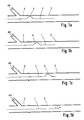
- Figure 1a shows a stage where part of an optical fibre member 1 has been introduced into a duct 2 by means of a blowing head 3.
- a blowing head which may be used is a blowing head containing a venturi as described in our pending UK application 8827460.0, and as also described below with reference to Figures 2a to 2e.
- Figure 1a shows the optical fibre member 1 with slack at the upstream end of the duct 2, this slack taking the form of a ripple 4.
- the ripple is shown as being approximately sinusoidal, but it must be understood that, depending on the conditions, the ripple might assume some other shape. It must also be understood that although the description assumes that only a single ripple is propagating along the fibre member there are preferably many such ripples propagating simultaneously.
- a ripple may be generated in the fibre member, for subsequent propagation along the fibre member, are described in more detail below. However, some general points may be noted at this stage.
- the formation of the ripple may be assisted either by moving the fibre member from side to side, i.e. by a transverse oscillation, or it may be generated by an axial oscillation, for example by feeding the fibre member to the upstream end of the duct via a mechanism which continuously receives the fibre member but which intermittently prevents its being passed to the duct.
- a particular device may be provided for deliberately generating these ripples. However, under some circumstances the ripples may be automatically generated, as will be explained further below.
- a major factor affecting the formation of ripples is the elastic behaviour, characterised by the flexural rigidity of the fibre member. If the fibre member is too stiff or if the fibre diameter is too large in relation to the duct bore diameter, it will not be possible to generate a ripple of sufficiently great amplitude and sufficiently short wavelength to be of any practical use.
- the air supply can be pulsed. Pulsing of the air supply will cause local perturbations in the pressure profile to travel along at least part of the duct. These will exaggerate the local pressure gradient, thus increasing the normal pressure force. The following analysis, however, ignores any such pulsing.
- the wave moves forward if this term exceeds the contribution of two terms: i) the degradation of energy by internal friction as the wave deforms the fibre member, E int , and ii) the energy required to "peel" the fibre member at the points of contact between the fibre member and the duct E surf .
- Equation (11) gives the important result that the surface shear stress acting on the fibre member is inversely proportional to the local pressure.
- the local mean flow velocity can also be shown to vary inversely as the pressure.
- the viscous drag force acting on the fibre member is given by where l F if the installed length of the fibre member.
- equations (11) and (12) demonstrate the important result that the contribution of the surface shear stress to the viscous drag force is not evenly distributed over the surface of the fibre member. The smallest contribution occurs where the fibre member enters the duct and the contribution increases progressively so that the largest contribution is at the leading end of the fibre member. This fact is important in assessing the significance of wave transport.
- the shear stress acting on the fibre is a function of the relative velocity (V g - V1), and so for a moving fibre the imbalance between the contributions of the surface shear stress between the leading and trailing ends of the fibre member are even more severe than for the fibre member at rest.
- the wave transport mechanism Since the ripples or waves are formed just upstream of or at the entry plane of the duct the wave transport mechanism is most active and significant in the sections immediately downstream of the entry plane of the duct. It is in just this region that the viscous drag mechanism is least effective. Thus the contributions of viscous drag and wave transport are seen to be complementary.
- the shape of the wave and the rate of propagation are influenced by the interaction of elastic, surface, aerodynamic, and gravitational forces.
- the magnitudes and relative importance of the forces change as the wave advances.
- FIGs 1a to 1d are drawn on the basis that wave transport is the sole mechanism by which the fibre member advances, and so the leading tip of the fibre member is shown as remaining stationary between Figure 1a and Figure 1c. In practice this may not be so since there will always be at least one other force operating on the whole length of the fibre member, namely viscous drag, and the effect of viscous drag is complementary to the effect of wave propagation, as stated above.
- EI the flexural rigidity of the optical fibre, which is the product of Young's modulus and the second moment of area and is normally denoted as EI.
- EI Young's modulus
- Figure 3 of EP-A-157610 in which seven optical fibres are disposed in a close-packed array and surrounded by an inner sheath which holds them together and an outer foamed sheath
- the value of EI is of the order of 10 ⁇ 4 Nm2.
- the value of EI for the same construction, but with four optical fibres rather than seven, is of the same order.
- An optical fibre member produced by such a method and apparatus has the characteristic that the foam sheath is not bonded to the optical fibre itself so that the optical fibre is free to slide with respect to the sheath when the optical fibre member bends.
- a fibre made as just described was found to have a value of EI equal to 0.85 x 10 ⁇ 6 Nm2. Its kinetic coefficient of friction with respect to medium density polyethylene, of which the duct may appropriately be made, as measured by means of the tilting table method, was found to be 0.3.
- Such a fibre was found in practice to be capable of being conveyed to a significant extent by the propagation of slack in a duct of 3.5 mm internal diameter, as is shown for example by Table 1 below.
- the method of the present invention is used preferably to install a fibre member having an EI value of less than 10 ⁇ 4Nm2, more preferably less than 10 ⁇ 5Nm2, and still more preferably less than 10 ⁇ 6 Nm2.
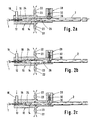
- FIGs 2a to 2e show successive stages in the operation of an embodiment of a method of the invention, in which the optical fibre member 1 is fed into the duct 2 by a venturi.
- the device 10 comprises a body 12 defining an elongate passage 14 the downstream end of which communicates with the duct 2. Adjacent its upstream end, the passage 14 has a side arm 16 to which is connected a source of gas under pressure, preferably a source of compressed air. Such a source can be of any conventional type.
- the passage 14 is constricted on the downstream side of the side arm 16 to define a constriction 18.
- a tube 20 which has a narrow bore and which is referred to herein as a hypodermic tube, extends into the passage 14 so that the downstream end thereof is situated in, or adjacent to the constriction 18.
- the longitudinal position of the hypodermic tube 20 may be adjustable with respect to the constriction 18 by adjusting means (not shown), so that the downstream end of the hypodermic tube 20 can be located at the zone of minimum pressure.
- each vent tube 22 communicates with atmosphere via a control valve 23 which allows a controlled, adjustable amount of air to pass from the vent tube to atmosphere.
- the end of each vent tube remote from its connection to the passage 14 may communicate with a noise suppressor, which is a chamber designed to absorb noise generated by the flow of high pressure air venting to atmosphere.
- a noise suppressor which is a chamber designed to absorb noise generated by the flow of high pressure air venting to atmosphere.
- Other forms of venting can be used instead of the pair of vent tubes.
- air of low moisture content is introduced into the side arm 16 at high pressure, for example 100 psig and flows at high velocity through the constriction 18 which acts as a venturi.
- the venturi exploits the properties of a gas flow passing through a constriction. Within the constriction the axial pressure distribution exhibits a minimum.
- the dimensions of the venturi, the values of the supply pressure and the mass flow rate of air are selected so that the minimum pressure is below atmospheric pressure.
- the velocity of the air flow in the constriction will reach the speed of sound. In some embodiments the flow throughout the venturi device will remain entirely subsonic.
- a fibre retention device 28 which comprises, by way of illustration, a piston 30 which is movably radially with respect to the passage 14 between a retracted position shown in Figures 2a and 2c, and a fibre clamping position shown in Figure 2b, 2d and 2e.
- the piston is biased into its retracted position by a spring 32 and urged into its clamping position by pneumatic or hydraulic pressure, by electromechanical means, or any other suitable means (not shown).
- the piston 30 is then retracted, and the ripple 4 is able to propagate down the fibre member 1.
- the piston 30 then returns to its clamping position, as shown in Figure 2e, and a further ripple begins to form.
- the apparatus is thus able to produce and propagate a succession of ripples.
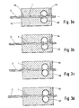
- Figures 3a to 3d show successive stages in the operation of an alternative embodiment.
- This too has a fibre retention device 28, which can be the same as the device 28 shown in Figures 2a to 2e and is therefore not shown here in detail.
- the apparatus of Figures 3a to 3d differs from that of Figures 2a to 2e in that the venturi device is replaced by an insertion device having a pair of wheels 40 which grip the fibre member 1 and urge it forwardly.
- the wheels are located in a chamber 42 which is maintained at a pressure above atmospheric.
- the air which is to flow down the duct 2 is introduced through an air inlet 44 to a location immediately upstream of the wheels 40.
- Figures 4a to 4c and Figures 5a to 5b show another embodiment, this time one in which ripples are generated at irregular intervals but nevertheless frequently enough to play a significant role in the transport of the fibre member through the duct.
- the ripple is shown as being approximately helical, but it must be understood that, depending on the conditions, the ripple might assume some other shape.
- venturi device 50 As in Figures 2a to 2e, the arrangement shown in Figures 4a to 4c, and Figures 5a to 5b, uses a venturi device, which is here represented by reference numeral 50.
- the venturi device has hypodermic tube 52 through which the optical fibre member 1 enters, a side arm 54 through which air is supplied under pressure and vent tubes 56 controlled by control valves 58.
- the venturi device serves to introduce the fibre member 1 into the upstream end of the duct 2.
- the fibre member 1 is introduced into the tube 20 from a freely rotating fibre reel 60 (see Figures 5a and 5b) via a capstan 62 around which several turns are wound. Drive is applied to the capstan 62 via a drive shaft 64 which is indicated in part.
- the effect of this method of fibre introduction can be seen in Figures 4a to 4c.
- Figure 4a the amount of fibre which has been fed by the venturi device into the duct 2 is less than the amount which the capstan has unreeled from the fibre reel 60. Accordingly a fibre loop 66 appears between the capstan and the inlet to the tube 52. Because the fibre member is now no longer tensioned around the capstan it is no longer driven by the capstan, which continues to rotate while leaving the fibre member unaffected.
- slack is produced in the fibre member at the upstream end of the duct 2. This is achieved by venting a proportion of the air flow through the vent tubes such that the fluid drag force exerted on the fibre member in the duct 2 (taken in conjunction with the other forces acting on it) is insufficient to carry the fibre found at the rate at which it is being conveyed to the duct by force imparted to it by the venturi.
- the single buffered fibre had a buffering layer of foamed ethylene vinyl acetate and had the parameters given hereinabove for such a fibre.
- Installation was by means of an apparatus as shown in Figures 4a to 4c, 5a and 5b.
- An air flow through the duct was generated by having the air pressure at the upstream end of the duct at 0.7 bar above atmospheric, and atmospheric pressure at the downstream end. The air flow varied over the course of installation, but was 5.3 l/min by the time the fibre was fully installed.
- an optical fibre member of the type described in EP-A-157610 was installed using a wheeled head of the same general design as that shown in EP-A-108590.
- the fibre member had four individual optical fibres held in an outer sheath arrangement.
- the pressure across the duct was 1.0 bar and the air flow through the duct with the fibre member fully installed was 5.2 l/min.
- the wheels of the wheeled head were driven by a constant torque motor.
- ripples can be induced in the stiffer fibre member, and a modest increase in the speed of travel obtained by operating under conditions where such ripples exist, the art in relation to such stiffer fibre members contains express instructions that buckling of the fibre member is to be avoided in case the fibre member should jam in the duct in which it is being installed.
Landscapes
- Physics & Mathematics (AREA)
- Engineering & Computer Science (AREA)
- Manufacturing & Machinery (AREA)
- General Physics & Mathematics (AREA)
- Optics & Photonics (AREA)
- Light Guides In General And Applications Therefor (AREA)
- Electric Cable Installation (AREA)
Applications Claiming Priority (2)
| Application Number | Priority Date | Filing Date | Title |
|---|---|---|---|
| GB888809594A GB8809594D0 (en) | 1988-04-22 | 1988-04-22 | Method of conveying optical fibre member |
| GB8809594 | 1988-04-22 |
Publications (2)
| Publication Number | Publication Date |
|---|---|
| EP0338856A2 true EP0338856A2 (fr) | 1989-10-25 |
| EP0338856A3 EP0338856A3 (fr) | 1990-06-06 |
Family
ID=10635689
Family Applications (1)
| Application Number | Title | Priority Date | Filing Date |
|---|---|---|---|
| EP89304003A Withdrawn EP0338856A3 (fr) | 1988-04-22 | 1989-04-21 | Procédé d'installation d'un corps à fibre optique et dispositif adapté |
Country Status (10)
| Country | Link |
|---|---|
| EP (1) | EP0338856A3 (fr) |
| JP (1) | JPH0243505A (fr) |
| CN (1) | CN1039120A (fr) |
| AU (1) | AU3327589A (fr) |
| DK (1) | DK194889A (fr) |
| FI (1) | FI891904A (fr) |
| GB (2) | GB8809594D0 (fr) |
| MY (1) | MY104431A (fr) |
| NO (1) | NO891652L (fr) |
| PT (1) | PT90340A (fr) |
Cited By (7)
| Publication number | Priority date | Publication date | Assignee | Title |
|---|---|---|---|---|
| DE3938387A1 (de) * | 1989-11-18 | 1991-05-23 | Rheydt Kabelwerk Ag | Verfahren zum bestuecken eines hohlen aufnahmekoerpers mit einem oder mehreren lichtwellenleitern |
| FR2655783A1 (fr) * | 1989-12-13 | 1991-06-14 | Pecot Alain | Pistolet d'injection, notamment pour le tirage de cables dans une conduite de grande longueur. |
| US5169126A (en) * | 1982-11-08 | 1992-12-08 | British Telecommunications Public Limited Company | Method and apparatus for installing transmission lines |
| US5199689A (en) * | 1988-06-02 | 1993-04-06 | British Telecommunications Public Limited Company | Transmission line installation |
| US6079261A (en) * | 1995-11-17 | 2000-06-27 | Nextrom Holding S.A. | Method and arrangement for levelling out tension variation of an optical fibre |
| US6364290B1 (en) | 1996-09-19 | 2002-04-02 | British Telecommunications Public Limited Company | Blowing head including a buckle detector |
| EP1978389A1 (fr) * | 2007-04-02 | 2008-10-08 | BRITISH TELECOMMUNICATIONS public limited company | Installation de câble soufflé |
Families Citing this family (4)
| Publication number | Priority date | Publication date | Assignee | Title |
|---|---|---|---|---|
| US5172890A (en) * | 1991-04-10 | 1992-12-22 | Kiyoshi Horii | Installation device |
| JP2803695B2 (ja) * | 1991-11-28 | 1998-09-24 | 清之 堀井 | 通線装置 |
| KR20130087044A (ko) * | 2010-11-16 | 2013-08-05 | 플루메타쯔 홀딩 에스.아. | 도관에 세장형 요소를 설치하기 위한 덕트 로드 시스템 |
| SG11201811645PA (en) * | 2016-08-04 | 2019-02-27 | Plumettaz Holding S A | Apparatus and method for jetting a cable into a duct |
Citations (5)
| Publication number | Priority date | Publication date | Assignee | Title |
|---|---|---|---|---|
| EP0108590A1 (fr) * | 1982-11-08 | 1984-05-16 | BRITISH TELECOMMUNICATIONS public limited company | Fibres optiques de transmission |
| GB2157019A (en) * | 1984-03-29 | 1985-10-16 | Bicc Plc | Manufacture of optical cable |
| GB2179471A (en) * | 1985-08-19 | 1987-03-04 | Bicc Plc | Introducing an optical fibre guide into a tube under fluid pressure |
| EP0319194A1 (fr) * | 1987-11-25 | 1989-06-07 | BICC Public Limited Company | Méthode et dispositif pour l'installation d'un corps à fibre optique |
| EP0323028A1 (fr) * | 1987-11-25 | 1989-07-05 | BICC Public Limited Company | Procédé et dispositif d'installation pneumatique d'un corps à fibre optique |
Family Cites Families (2)
| Publication number | Priority date | Publication date | Assignee | Title |
|---|---|---|---|---|
| FR2525036A1 (fr) * | 1982-04-08 | 1983-10-14 | Jeumont Schneider | Procede et dispositif pour la mise en place d'un cable a l'interieur d'un conduit |
| EP0152720A1 (fr) * | 1984-02-22 | 1985-08-28 | Plumettaz Sa | Dispositif de commande d'un transporteur intermédiaire |
-
1988
- 1988-04-22 GB GB888809594A patent/GB8809594D0/en active Pending
-
1989
- 1989-04-20 DK DK194889A patent/DK194889A/da not_active Application Discontinuation
- 1989-04-21 NO NO89891652A patent/NO891652L/no unknown
- 1989-04-21 FI FI891904A patent/FI891904A/fi not_active Application Discontinuation
- 1989-04-21 EP EP89304003A patent/EP0338856A3/fr not_active Withdrawn
- 1989-04-21 JP JP1103311A patent/JPH0243505A/ja active Pending
- 1989-04-21 AU AU33275/89A patent/AU3327589A/en not_active Abandoned
- 1989-04-21 PT PT90340A patent/PT90340A/pt not_active Application Discontinuation
- 1989-04-21 GB GB8909119A patent/GB2217926B/en not_active Expired - Lifetime
- 1989-04-22 MY MYPI89000517A patent/MY104431A/en unknown
- 1989-04-22 CN CN89103505.2A patent/CN1039120A/zh active Pending
Patent Citations (5)
| Publication number | Priority date | Publication date | Assignee | Title |
|---|---|---|---|---|
| EP0108590A1 (fr) * | 1982-11-08 | 1984-05-16 | BRITISH TELECOMMUNICATIONS public limited company | Fibres optiques de transmission |
| GB2157019A (en) * | 1984-03-29 | 1985-10-16 | Bicc Plc | Manufacture of optical cable |
| GB2179471A (en) * | 1985-08-19 | 1987-03-04 | Bicc Plc | Introducing an optical fibre guide into a tube under fluid pressure |
| EP0319194A1 (fr) * | 1987-11-25 | 1989-06-07 | BICC Public Limited Company | Méthode et dispositif pour l'installation d'un corps à fibre optique |
| EP0323028A1 (fr) * | 1987-11-25 | 1989-07-05 | BICC Public Limited Company | Procédé et dispositif d'installation pneumatique d'un corps à fibre optique |
Cited By (11)
| Publication number | Priority date | Publication date | Assignee | Title |
|---|---|---|---|---|
| US5169126A (en) * | 1982-11-08 | 1992-12-08 | British Telecommunications Public Limited Company | Method and apparatus for installing transmission lines |
| US6173107B1 (en) | 1982-11-08 | 2001-01-09 | British Telecommunications Public Limited Company | Method and apparatus for installing transmissions |
| US6328283B1 (en) | 1982-11-08 | 2001-12-11 | British Telecommunications Public Limited Company | Method and apparatus for installing transmission lines |
| US5199689A (en) * | 1988-06-02 | 1993-04-06 | British Telecommunications Public Limited Company | Transmission line installation |
| DE3938387A1 (de) * | 1989-11-18 | 1991-05-23 | Rheydt Kabelwerk Ag | Verfahren zum bestuecken eines hohlen aufnahmekoerpers mit einem oder mehreren lichtwellenleitern |
| DE3938387C2 (de) * | 1989-11-18 | 1998-09-10 | Rheydt Kabelwerk Ag | Verfahren zum Bestücken eines rohrförmigen Aufnahmekörpers mit zumindest einem Lichtwellenleiter |
| FR2655783A1 (fr) * | 1989-12-13 | 1991-06-14 | Pecot Alain | Pistolet d'injection, notamment pour le tirage de cables dans une conduite de grande longueur. |
| US6079261A (en) * | 1995-11-17 | 2000-06-27 | Nextrom Holding S.A. | Method and arrangement for levelling out tension variation of an optical fibre |
| US6364290B1 (en) | 1996-09-19 | 2002-04-02 | British Telecommunications Public Limited Company | Blowing head including a buckle detector |
| EP1978389A1 (fr) * | 2007-04-02 | 2008-10-08 | BRITISH TELECOMMUNICATIONS public limited company | Installation de câble soufflé |
| WO2008119976A1 (fr) * | 2007-04-02 | 2008-10-09 | British Telecommunications Public Limited Company | Installation de câble soufflé |
Also Published As
| Publication number | Publication date |
|---|---|
| MY104431A (en) | 1994-03-31 |
| CN1039120A (zh) | 1990-01-24 |
| DK194889D0 (da) | 1989-04-20 |
| DK194889A (da) | 1989-10-23 |
| FI891904A (fi) | 1989-10-23 |
| NO891652D0 (no) | 1989-04-21 |
| GB2217926B (en) | 1991-11-20 |
| EP0338856A3 (fr) | 1990-06-06 |
| GB8809594D0 (en) | 1988-05-25 |
| PT90340A (pt) | 1989-11-10 |
| JPH0243505A (ja) | 1990-02-14 |
| AU3327589A (en) | 1989-10-26 |
| GB8909119D0 (en) | 1989-06-07 |
| NO891652L (no) | 1989-10-23 |
| FI891904A0 (fi) | 1989-04-21 |
| GB2217926A (en) | 1989-11-01 |
Similar Documents
| Publication | Publication Date | Title |
|---|---|---|
| US5199689A (en) | Transmission line installation | |
| EP0287225B1 (fr) | Dispositif d'installation pour fibre optique | |
| EP0338856A2 (fr) | Procédé d'installation d'un corps à fibre optique et dispositif adapté | |
| EP0445622B1 (fr) | Procédé d'installation d'un composant à fibre optique et appareil permettant son application | |
| US4990033A (en) | Method and apparatus for blowing an optical fibre member | |
| JP2788991B2 (ja) | 伝送線路部材の推進力制御装置および伝送線路吹き流し装置 | |
| JPH02210306A (ja) | 光ファイバの挿通方法 | |
| US4640576A (en) | Method and apparatus for tubing optical fibers | |
| JPH02265109A (ja) | 複合ケーブルおよび光ファイバの挿通方法 | |
| GB2212940A (en) | Method and apparatus for blowing an optical fibre member | |
| US5197715A (en) | Method for pulling plug for installing a cable in a cable conduit | |
| US3006607A (en) | Method and apparatus for introducing lines through conduits | |
| US5121901A (en) | Sheathed optical fibres and method of installing such fibres | |
| US4702404A (en) | Method and apparatus for regulating speed of a longitudinally moving fiber | |
| JPS634163B2 (fr) | ||
| JP2642430B2 (ja) | 管への線条体挿通方法およびその装置 | |
| JP2642428B2 (ja) | 管への線条体挿通方法およびその装置 | |
| JPH03265801A (ja) | 通信用線材の布設方法および装置 |
Legal Events
| Date | Code | Title | Description |
|---|---|---|---|
| PUAI | Public reference made under article 153(3) epc to a published international application that has entered the european phase |
Free format text: ORIGINAL CODE: 0009012 |
|
| AK | Designated contracting states |
Kind code of ref document: A2 Designated state(s): AT BE CH DE ES FR GB GR IT LI LU NL SE |
|
| PUAL | Search report despatched |
Free format text: ORIGINAL CODE: 0009013 |
|
| AK | Designated contracting states |
Kind code of ref document: A3 Designated state(s): AT BE CH DE ES FR GB GR IT LI LU NL SE |
|
| 17P | Request for examination filed |
Effective date: 19901115 |
|
| 17Q | First examination report despatched |
Effective date: 19920320 |
|
| STAA | Information on the status of an ep patent application or granted ep patent |
Free format text: STATUS: THE APPLICATION IS DEEMED TO BE WITHDRAWN |
|
| 18D | Application deemed to be withdrawn |
Effective date: 19920731 |