EP0338697A1 - Method and system for variable frequency electromagnetic water treatment - Google Patents
Method and system for variable frequency electromagnetic water treatment Download PDFInfo
- Publication number
- EP0338697A1 EP0338697A1 EP89303362A EP89303362A EP0338697A1 EP 0338697 A1 EP0338697 A1 EP 0338697A1 EP 89303362 A EP89303362 A EP 89303362A EP 89303362 A EP89303362 A EP 89303362A EP 0338697 A1 EP0338697 A1 EP 0338697A1
- Authority
- EP
- European Patent Office
- Prior art keywords
- frequency
- signal
- fluid
- electromagnetic
- absorption
- Prior art date
- Legal status (The legal status is an assumption and is not a legal conclusion. Google has not performed a legal analysis and makes no representation as to the accuracy of the status listed.)
- Granted
Links
Images


Classifications
-
- C—CHEMISTRY; METALLURGY
- C02—TREATMENT OF WATER, WASTE WATER, SEWAGE, OR SLUDGE
- C02F—TREATMENT OF WATER, WASTE WATER, SEWAGE, OR SLUDGE
- C02F1/00—Treatment of water, waste water, or sewage
- C02F1/48—Treatment of water, waste water, or sewage with magnetic or electric fields
- C02F1/487—Treatment of water, waste water, or sewage with magnetic or electric fields using high frequency electromagnetic fields, e.g. pulsed electromagnetic fields
-
- C—CHEMISTRY; METALLURGY
- C23—COATING METALLIC MATERIAL; COATING MATERIAL WITH METALLIC MATERIAL; CHEMICAL SURFACE TREATMENT; DIFFUSION TREATMENT OF METALLIC MATERIAL; COATING BY VACUUM EVAPORATION, BY SPUTTERING, BY ION IMPLANTATION OR BY CHEMICAL VAPOUR DEPOSITION, IN GENERAL; INHIBITING CORROSION OF METALLIC MATERIAL OR INCRUSTATION IN GENERAL
- C23F—NON-MECHANICAL REMOVAL OF METALLIC MATERIAL FROM SURFACE; INHIBITING CORROSION OF METALLIC MATERIAL OR INCRUSTATION IN GENERAL; MULTI-STEP PROCESSES FOR SURFACE TREATMENT OF METALLIC MATERIAL INVOLVING AT LEAST ONE PROCESS PROVIDED FOR IN CLASS C23 AND AT LEAST ONE PROCESS COVERED BY SUBCLASS C21D OR C22F OR CLASS C25
- C23F15/00—Other methods of preventing corrosion or incrustation
-
- C—CHEMISTRY; METALLURGY
- C02—TREATMENT OF WATER, WASTE WATER, SEWAGE, OR SLUDGE
- C02F—TREATMENT OF WATER, WASTE WATER, SEWAGE, OR SLUDGE
- C02F2201/00—Apparatus for treatment of water, waste water or sewage
- C02F2201/46—Apparatus for electrochemical processes
- C02F2201/461—Electrolysis apparatus
- C02F2201/46105—Details relating to the electrolytic devices
- C02F2201/4612—Controlling or monitoring
- C02F2201/46125—Electrical variables
- C02F2201/4614—Current
-
- C—CHEMISTRY; METALLURGY
- C02—TREATMENT OF WATER, WASTE WATER, SEWAGE, OR SLUDGE
- C02F—TREATMENT OF WATER, WASTE WATER, SEWAGE, OR SLUDGE
- C02F2303/00—Specific treatment goals
- C02F2303/22—Eliminating or preventing deposits, scale removal, scale prevention
Definitions
- This invention relates generally to the treatment of water or other liquids for the purpose of preventing rust, and scaling of various liquid contacting surfaces. More particularly, the invention provides an electromagnetic water treatment method and system whereby water is treated by an electromagnetic signal, the frequency of which has been determined to provide optimal absorption and/or emission of energy by the particular atomic and molecular matter present in the system.
- the invention is particularly applicable where inhibition or reversal of rust or scale is desired.
- the invention will be described herein with specific reference to the inhibition or reversal of rust and/or scale. It must be appreciated, however, that the invention has broader utility and may be used in a variety of applications including virtually any application wherein electromagnetic energy is used to bring about a reduction in biological/chemical oxygen demand; to alter the ionization or reactivity of other elements including but certainly not limited to copper, gold, carbon and platinum; to alter the electromechanical characteristics of water or other liquids; or to control the solubility of various substances within water or liquids.
- United States Patent No. 3,511,776 issued to Avampato discloses a method of using various wave lengths of electromagnetic energy, mostly within the ultraviolet and x-ray spectra, to cause ionic species within a flowing water system to become more susceptible to attraction by a subsequent magnetic field.
- United States Patent No. 3,625,884 issued to Waltrip discloses a sewage treatment method which employs multiple signal generators to simultaneously provide audio frequency and/or radio frequency energy at a number of different frequencies.
- the frequency output of each separate signal generator may be selected on the basis of the mineral content of the untreated sewage.
- United States Patent No. 4,365,975 issued to Williams et al. discloses a method of recovering alkali metal constituents from coal gasification residues by subjecting the residues to electromagnetic energy in the radiofrequency-microwave (0.1-105 MHz) range. Such electromagnetic radiation is purported to facilitate extraction of the metal.
- United States Patent No. 3,767,545 issued to Lucero discloses a device which uses ultraviolet radiation to make certain ions more susceptible to magnetic attraction. Lucero recognizes that, theoretically, there exists a preferred wavelength for each ion that is to be rendered more susceptible to magnetic attraction. Lucero utilizes a separate magnet and a vortex inducing apparatus to separate undesired ions from a flowing water stream.
- the methods and devices of the prior art utilize electromagentic energy to bring about various effects on atomic or molecular matter contained in a solution or suspension.
- One of the purported advantages of many such prior art electromagnetic devices is that they eliminate or reduce the need for the addition of chemical water treatment agents.
- many of the prior art methods and devices have proven to be only minimally or sporadically effective in certain applications.
- the prior art devices and methods are, in many cases, confounded by technical complexity making such devices and methods expensive to manufacture and difficult to install.
- the present invention overcomes the above-stated shortcomings in the art by providing a versatile and relatively simple method and system for employing variable frequency electromagnetic energy to treat various liquids and to inhibit or reverse the formation of rust or scaling of various liquid-contacting surfaces. More fundamentally, the present invention provides a method for determining the optimal electromagentic frequency to be employed in the electromagnetic treatment of a liquid, such optimal frequency being a function of the particular atomic and/or molecular matter present in the treated fluid. The method of the present invention may be employed to qualitatively and/or quantitatively alter the formation of various chemical compounds within the fluid or on fluid-contacting surfaces.
- an electromagnetic fluid treatment method whereby electromagnetic signals of known current intensity and varying frequency are initially directed into a fluidic system such as a water boiler, hot water tank, industrial water system, or the like.
- a fluidic system such as a water boiler, hot water tank, industrial water system, or the like.
- Such signals may be provided directly via one or more probes extending into the fluid, may be provided indirectly via attachment point(s) on various fluid contacting surfaces or may be applied by any other means capable of directing the desired electromagnetic energy into the fluid.
- the current intensity of the signals is subsequently measured at a separate location some distance from the point(s) at which the signals are initially delivered. As the signal frequency is varied, the current intensity measured at the separate location will typically vary above and below the known current intensity of the signals.
- Such measured variations in current intensity relative to the corresponding variations in signal frequency provide a "profile" of the energy absorbing and/or emitting characteristics of the particular atomic and molecular matter dissolved or suspended within the liquid.
- the frequencies at which maximal absorption and maximal emission are observed or any other selected frequency may then be utilized, solely or interchangeably, for subsequent electromagnetic treatment of the liquid.
- the relationship between current absorption and/or emission and the frequency of the signal may be periodically redetermined. Based on such redeterminations, adjustment(s) in treatment frequency may be made during the course of the treatment period. Such periodic optimization of the treating frequency insures that the most effective anti-scaling effects will be maintained during the ongoing treatment.
- the initial test signals may be generated by any type of variable frequency electromagnetic generator capable of generating signals within effective frequency ranges.
- a broad range e.g. 0.1 KHz to 1000 MHz
- Signal generators having narrower frequency ranges such as 0.1 KHz - 100 MHz or 0.1 KHz-500 MHz may, of course, be employed, depending upon solute content of the liquid and the specific application involved.
- the electromagnetic signals utilized by the present invention may be delivered by way of probes which extend directly into the liquids, or by way of attachment points located on liquid contacting surfaces capable of transmitting the signal into the liquids. In large installations such as industrial boilers and the like, multiple probes or attachment points may be utilized to insure that the signals are uniformly transmitted throughout the entire installation.
- the current intensity measurements may be made by any current measuring device capable of measuring within applicable ranges.
- the use of an oscilloscope may be advantageous where visualization of the waveform is desirable, however, a simple milliammeter will generally be an acceptable current measuring device for the present invention.
- the measuring device whether it be an oscilloscope, milliammeter, or other device, may be omitted from the system.
- the generator generates a signal at the approximate optimum frequency for the desired effect or treatment of the fluid. This type of operation may be conducted in situations where a known frequency has been used in other similar systems and omitting continuous measurement, redetermination and readjustment of the treatment frequency does not seriously reduce the effectiveness of the system.
- quantum electrodynamic theory speaks to the manner in which electromagnetic fields interact with atoms and molecules, as well as the resultant interactions between molecules.
- the theory of quantum electrodynamics is, in part, based on the relation between the energy of a quantum of light, the photon, and the frequency of any electromagnetic field corresponding to it.
- quantum electrodynamics it must be recognized that dynamic electromagnetic fields are known to interact with the various charged particles which form constituents of atoms and molecules (i.e. electrons).
- the external application of an electromagnetic field will bring about various disruptions of the internal fields which are responsible for the particular atomic or molecular structure and the interrelationships of the charged particles therein.
- the energy absorption/emission characteristics of a solution will vary as the frequency of the external electromagnetic field is varied.
- a principal object of the present invention is to provide a method and system for treating liquid with an electromagnetic signal, the frequency of which has been determined to correspond with a desired level of absorption or emission of energy by the particular atomic and/or molecular matter contained in the liquid.
- the desired treatment frequency will be the frequency at which maximum current absorption is observed.
- Another object of the present invention is to provide a convenient method and system for utilizing electromagnetic energy for the purpose of inhibiting the formation of rust or scale on various fluid contacting surfaces.
- Yet another object of the present invention is to provide a convenient method and system for altering, reversing and/or removing existing rust, and/or scale from fluid contacting surfaces.
- a still further object of the present invention is to provide a frequency-optimized electromagnetic liquid treatment method which is effective to prevent, inhibit or reverse the formation of rust and scale on liquid contacting surfaces regardless of whether the liquid remains static or is permitted to flow within the system.
- An additional object of the present invention is to provide a system which may be used in an application where the approximate frequency or effective frequency for the given desired treatment is known and measuring and adjustment are unnecessary.
- Figure 1 outlines a preferred liquid treatment method of the present invention in block diagram form which, for purposes of explanation, comprises a water treatment system.
- the initial step of providing varying frequency test signals 10 may, depending upon the frequency range desired, be accomplished by a variety of devices capable of generating electromagnetic energy. However, it is typically preferable to utilize a signal generator capable of providing electromagnetic energy within the radiofrequency band. Such frequency range is generally sufficient to develop a usable absorption/emission profile for most water systems.
- the signal generating device is directly or indirectly connected to the water being treated.
- the term "absorption/emission" profile as used herein means a visual or recorded summary of the absorption and emission characteristics of the liquid being treated for each of the test signals generated by the generator.
- the second step of measuring current intensity at a remote location 12 is accomplished by connecting any appropriately calibrated current measuring device to a point in the system where it will directly or indirectly sense the current intensity of the signal within the water being treated.
- the water between the point at which the test signals are provided 10, i.e. signal application point", and the remote location at which the current intensity is measured, i.e. "current measurement point”, should be consistent and non-disrupted. Closed valves or large air filled voids within the water may disrupt the signal and result in distorted or erroneous current intensity readings.
- the water between the signal application point and the current measurement point may be either standing or flowing, provided that consistency, i.e. a steady state condition, is maintained.
- the preferred embodiment employs an oscilloscope whereby the waveform of the signal may be visualized and additional waveform measurements may be made as required.
- a simple milliammeter will be an appropriate instrument for measuring current intensity at the remote location 12.
- the current measured at the remote location will vary as the frequency of the test signal varies.
- Such current variations relative to signal frequency are indicative of absorption or emission of energy by the atomic and molecular species present in the water.
- the measured current intensity relative to the corresponding test signal frequencies will generate an absorption/emission profile 14.
- Such profile in most cases, will extend over a frequency range of approximately 1 KHz to 100 MHz; however, any applicable frequency range may be employed.
- the next step is to select a treatment frequency 16.
- a treatment frequency 16 In most cases it is desirable to select the frequency at which maximal absorption of current is observed. Such is referred to as the maximal absorption frequency. It should be appreciated, however, in specific cases it may be desirable to select the observed maximal emission frequency or any other treatment frequency, the selection of which is made on the basis of the previously generated absorption/emission profile.
- an electromagnetic signal generator is set to provide a treatment signal at the selected frequency 18.
- a single variable frequency signal generator is used to provide the test signals 10 as well as the subsequent static frequency treatment signal 18.
- the operator may optionally repeat steps 10 through 14, thereby periodically regenerating absorption/emission profile data. If such newly generated absorption/emission profile data indicates a change in maximal absorption or emission frequency has occurred, the treatment frequency may be adjusted correspondingly.
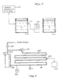
- FIG. 2 shows a schematic diagram of a preferred embodiment wherein a system of the present invention is used to treat an industrial boiler system.
- the system comprises a condensate tank 40, a boiler 42, and a heat exchanger 44.
- a water line 46 fluidly connects outlet port 48 of condensate tank 40 to the inlet port 50 of boiler 42.
- a transfer pump 52 is positioned within water line 46 for the purpose of pumping water from condensate tank 40 into boiler 42.
- a steam line 54 connects the steam outlet port 56 of boiler 42 to the inlet end 58 of coil-type heat exchanger 44.
- the steam condenses within the heat exchanger and a condensate line 60 carrying the condensate from the outlet end 62 of heat exchanger 44 to the inlet port 64 of condensate tank 40.
- the subject boiler system comprises a closed, continually recirculating hot water boiler arrangement.
- a variable frequency electromagnetic generator 70 is connected to three separate signal output probes.
- a milliammeter 78 is positioned so as to be in operative contact with the water circulating into boiler 42 thereby providing a means of measuring the current intensity of an electromagnetic signal emitted by signals generator 70 and directed into the water by probes 72, 74 and 76.
- an oscilloscope or any other current measuring means may also be employed for this purpose.
- the corresponding absorption/emission profile may be determined on the basis of the current measured by milliammeter 78 relative to the varied frequency of the electromagnetic signal.
- a complete absorption/emission profile for the system may be obtained and the signal frequency which produces maximal absorption or emission of energy may be determined.
- FIG. 3 two cut sections of heavily scaled pipe, labeled A and B, were removed from a commercial boiler.
- Plexiglass bottoms 100, 102 were bonded by silicone cement to one end of each pipe section, thereby forming separate, open-topped cylindrical containers having water-tight bottoms.
- a spark plug 104 was tapped through the wall of container A so as extend fully through the container wall. Both containers A and B were filled with tap water.
- a 0 to 50 MHz variable frequency electromagnetic generator 106 was attached to the spark plug 104.
- An oscilloscope 108 was attached to the first pipe section at a second point 110 some distance from the spark plug.
- a plurality of 20 volt (peak to peak) electromagnetic signals of varying frequency were then directed into the spark plug 104 and the current intensity at the second point 110 was measured by oscilloscope 108 so as to discern the absorption/emission profile of the water.
- a hot water heater 142 was connected to one end of a 220 foot long section of galvanized iron pipe 144.
- the opposite end of pipe section 144 was connected to the inlet line 148 of hot water heater 142.
- a recirculating pump 150 was positioned in line 144 so as to continually recirculate water from the outlet 140 of water heater 142, through the entire length of line 144 and again into water heater 142 via inlet line 148.
- a spark plug 152 was tapped through a wall of the pipe at its approximate midpoint and a variable frequency electromagnetic signal generator 154 was attached to the spark plug.
- a milliammeter 156 was attached to line 144 at a point some distance from the point at which spark plug 152 was mounted.
- the system was filled with tap water and pump 180 was activated. Electromagnetic signals of varying frequency, ranging from 1 KHz to 100 MHz, were then directed through the spark plug 152 with water continually circulating through the system. A milliammeter 156 was utilized to determine the current absorption/emission profile of the water. The maximum absorption frequency was determined to be 28.5 MHz. Thereafter, the signal generator 154 was set to generate a signal at the previously determined maximum absorption frequency of 28.5 MHz for a period of seven days during which time the recirculating pump was continually run. Quantities of make-up tap water, individually comprising about ten percent of the system volume, were added to the system each day through a water inlet valve 158 located in the inlet line 148 of the water heater 142.
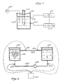
- a section of galvanized pipe 200 having approximately 1/8 inch of scale deposited on its inner surface was removed from an institutional boiler system.
- the section of pipe 200 measured 12 inches in length and approximately 3/4 of an inch in diameter.
- the removed pipe section 200 was suspended by iron wire 202 from the top of a water filled iron container 204 so as to be mostly immersed in the water without contacting the sides of the container.
- a spark plug 206 was tapped through one wall of the container and a 0-500 MHz variable frequency signal generator 208 was attached to the spark plug.
- the signal generator was powered by a 0-40 volt DC power source 210.
- the power source 210 was grounded to the wall 212 of the metal container.
- Maximum absorption and emission frequencies were determined by varying the frequency of signal generator 208 while measuring the current intensity of the signals within the water using milliammeter 220.
- the maximum absorption frequency was determined to be 40.5 MHz while maximum emission was observed at 11.0 MHz.
- Treatment was thereafter delivered, alternating from day to day between such previously determined maximum absorption frequency and maximum emission frequency. After nine days of such alternating maximum absorption/maximum emission treatment, the scale which had been observed on the inner surface of pipe 200 was no longer present.
- two open containers C and D were joined by a section of galvanized 3/4-inch pipe 250 running through the wall of each container C and D near the upper rim thereof.
- the containers C and D were filled with tap water such that the water level in each container was above the respective inlet point of pipe 250.
- a separate polypropylene return line 252 was positioned to connect containers C and D, fluidly extending through the bottom of each container.
- a recirculation pump 254 was positioned within polypropylene return line 252 so as to continually recirculate water from container C through the polypropylene line 252 into container D and subsequently out of the top of container D through the galvanized connecting pipe 250 and again into container C.
- a section of uncoated iron wire 256 was immersed in the water contained in container C.
- Plexiglass lids were bonded over the tops of containers C and D, thereby providing a substantially water-tight, recirculating system.
- the circulation of tap water within the system was maintained at a rate of approximately 20 gallons per minute by recirculation pump 254.
- Spark plugs 262, 264, 266 and 268 were tapped through various points in the walls of pipe 250 and polypropylene return line 252 as shown.
- a 0-50 MHz variable frequency electromagnetic generator 270 was initially connected to spark plug 262.
- the wire 256 With no signal generated, the wire 256 rusted and turned a reddish-orange color in approximately three days.
- a signal of 20.0 MHz was generated and directed through spark plug 262 for a period of 24 hours, the rust disappeared and the wire appeared bare.
- the frequency was changed to 40.5 MHz for another 24 hours, the wire turned black with Fe3O4 deposits and, following another 24 hours at 35 MHz the wire exhibited red Fe3O4 deposits.
- the experiment was thrice repeated, putting the same frequency signals through each of the three remaining spark plugs 264, 266 and 268 and the results in each case were the same.
- a separate experiment was designed to test the continuity of the signal as it travels through a typical industrial boiler system as outlined in Figure 7.
- a water heater tank 300 having an outlet port 302 and an inlet port 304 was connected to approximately 200 feet of galvanized one inch steel pipe 306 such that the pipe 306 would extend between the outlet port 302 and the inlet port 304 of tank 300.
- a transfer pump 308 was positioned within line 306 to provide for a continual recirculation of water from the tank 300 through the pipe 306 and back into tank 300.
- a valved drain port 310 was also located at the base of pipe 306 and two-way valves 312 and 314 were positioned at opposite ends of pipe 306.
- the boiler 350 included a water inlet 352 and a steam outlet 354.
- Steam line 356 was connected to the steam outlet 354 of boiler 350 and through a coil-type condcnser 358.
- the outlet end of condenser 358 was connected to a condensate line 360.
- the condensate line 360 was connected to line 306 by way of a "T" connection.
- a two-way valve 362 was positioned in line 360 to permit control of the condensate flow through line 360 into pipe 306.
- a first spark plug 380 was tapped through the wall of pipe 306, while a second spark plug 382 was tapped into the water containing tank portion of boiler 350.
- a two channel electromagnetic generator 384 was operatively connected to spark plugs 380 and 382.
- a first signal (signal A) was emitted by channel 1 of generator 384 and was directed through spark plug 380, while a second signal (signal B) was emitted through channel 2 of generator 384 and directed through spark plug 382.
- a first oscilloscope 386 was connected to the approximate mid-point of steam line 356, while a second oscilloscope 388 was connected to the cold water inlet 290 of water tank 300.
- the water tank 300 and water line 306 were consistently filled with recirculating water.
- signal A is input directly via spark plug 380 into the water flowing through pipe 306.
- Signal B emitted through spark plug 382 positioned in boiler 350 was measured by scope B to determine the continuity and consistency of signal B as it was transmitted through boiler 350 and the attendant steam line 356 and/or the condensate line 360 and condenser 358.
- Signal B was received intermittently by scope B when connected through the condensate lines and condenser as shown 388. When, however, scope B was connected to steam line 356, signal B was received without interruption. An approximate fifty percent decrease in signal amplitude -- but no change in signal frequency -- was observed in steam line 356.
- the milliammeter, oscilloscope or other current measuring device need not be used in situations where known or otherwise consistent conditions exist.
- boilers are used.
- a frequency of approximately 40 MHz has proven to be useful for treatment of such boilers. Therefore, rather than incorporating measurement and adjustment devices, a 40 MHz signal can be used with such boilers, thereby minimizing the cost and complexity of the system.
- spot checking may be used to ensure that no dramatic departures from desired operational characteristics and results occur. This may be done by placing a measuring device on the boiler as described above and going through the measurement steps previously outlined, or by taking samples of the liquid being treated to a test facility to determine if significant changes have affected the absorption/emission profile.
- FIGURE 2 adequately illustrates such a system, if, for example, milliammeter 78 is eliminated. Again, one or more probes 72, 74, 76 may also be used to direct the energy into the liquid.
- the system of the present invention may also be used for shocking a system, e.g. a laundry boiler.
- a system e.g. a laundry boiler.
Abstract
Description
- This invention relates generally to the treatment of water or other liquids for the purpose of preventing rust, and scaling of various liquid contacting surfaces. More particularly, the invention provides an electromagnetic water treatment method and system whereby water is treated by an electromagnetic signal, the frequency of which has been determined to provide optimal absorption and/or emission of energy by the particular atomic and molecular matter present in the system.
- The invention is particularly applicable where inhibition or reversal of rust or scale is desired. Thus, the invention will be described herein with specific reference to the inhibition or reversal of rust and/or scale. It must be appreciated, however, that the invention has broader utility and may be used in a variety of applications including virtually any application wherein electromagnetic energy is used to bring about a reduction in biological/chemical oxygen demand; to alter the ionization or reactivity of other elements including but certainly not limited to copper, gold, carbon and platinum; to alter the electromechanical characteristics of water or other liquids; or to control the solubility of various substances within water or liquids.
- The prior art is replete with electromagnetic water treatment methods and devices. Many such methods and devices employ electromagnetic energy of fixed frequency. Examples of such fixed frequency devices are disclosed in United States Patent Nos. 4,659,479; 4,347,133; 4,228,323; 4,365,975; 4,582,629; 2,939,830; 4,151,090; 4,427,544; 4,407,719; and 3,715,305.
- Several other United States patents disclose specific methods and/or devices which employ varied and/or mixed frequency electromagnetic energy. For example, United States Patent No. 3,511,776 issued to Avampato discloses a method of using various wave lengths of electromagnetic energy, mostly within the ultraviolet and x-ray spectra, to cause ionic species within a flowing water system to become more susceptible to attraction by a subsequent magnetic field.
- United States Patent No. 3,625,884 issued to Waltrip discloses a sewage treatment method which employs multiple signal generators to simultaneously provide audio frequency and/or radio frequency energy at a number of different frequencies. The frequency output of each separate signal generator may be selected on the basis of the mineral content of the untreated sewage.
- United States Patent No. 4,365,975 issued to Williams et al. discloses a method of recovering alkali metal constituents from coal gasification residues by subjecting the residues to electromagnetic energy in the radiofrequency-microwave (0.1-10⁵ MHz) range. Such electromagnetic radiation is purported to facilitate extraction of the metal.
- Additionally, United States Patent No. 3,767,545 issued to Lucero discloses a device which uses ultraviolet radiation to make certain ions more susceptible to magnetic attraction. Lucero recognizes that, theoretically, there exists a preferred wavelength for each ion that is to be rendered more susceptible to magnetic attraction. Lucero utilizes a separate magnet and a vortex inducing apparatus to separate undesired ions from a flowing water stream.
- In general, the methods and devices of the prior art utilize electromagentic energy to bring about various effects on atomic or molecular matter contained in a solution or suspension. One of the purported advantages of many such prior art electromagnetic devices is that they eliminate or reduce the need for the addition of chemical water treatment agents. However, many of the prior art methods and devices have proven to be only minimally or sporadically effective in certain applications. Additionally, the prior art devices and methods are, in many cases, confounded by technical complexity making such devices and methods expensive to manufacture and difficult to install.
- The present invention overcomes the above-stated shortcomings in the art by providing a versatile and relatively simple method and system for employing variable frequency electromagnetic energy to treat various liquids and to inhibit or reverse the formation of rust or scaling of various liquid-contacting surfaces. More fundamentally, the present invention provides a method for determining the optimal electromagentic frequency to be employed in the electromagnetic treatment of a liquid, such optimal frequency being a function of the particular atomic and/or molecular matter present in the treated fluid. The method of the present invention may be employed to qualitatively and/or quantitatively alter the formation of various chemical compounds within the fluid or on fluid-contacting surfaces.
- In accordance with one embodiment of the present invention, there is provided an electromagnetic fluid treatment method whereby electromagnetic signals of known current intensity and varying frequency are initially directed into a fluidic system such as a water boiler, hot water tank, industrial water system, or the like. Such signals may be provided directly via one or more probes extending into the fluid, may be provided indirectly via attachment point(s) on various fluid contacting surfaces or may be applied by any other means capable of directing the desired electromagnetic energy into the fluid. The current intensity of the signals is subsequently measured at a separate location some distance from the point(s) at which the signals are initially delivered. As the signal frequency is varied, the current intensity measured at the separate location will typically vary above and below the known current intensity of the signals. Such measured variations in current intensity relative to the corresponding variations in signal frequency provide a "profile" of the energy absorbing and/or emitting characteristics of the particular atomic and molecular matter dissolved or suspended within the liquid. The frequencies at which maximal absorption and maximal emission are observed or any other selected frequency may then be utilized, solely or interchangeably, for subsequent electromagnetic treatment of the liquid.
- In accordance with another aspect of the invention, the relationship between current absorption and/or emission and the frequency of the signal may be periodically redetermined. Based on such redeterminations, adjustment(s) in treatment frequency may be made during the course of the treatment period. Such periodic optimization of the treating frequency insures that the most effective anti-scaling effects will be maintained during the ongoing treatment.
- In accordance with an even further aspect of the present invention, the initial test signals may be generated by any type of variable frequency electromagnetic generator capable of generating signals within effective frequency ranges. A broad range (e.g. 0.1 KHz to 1000 MHz) is sufficient for water containing systems in general. Signal generators having narrower frequency ranges such as 0.1 KHz - 100 MHz or 0.1 KHz-500 MHz may, of course, be employed, depending upon solute content of the liquid and the specific application involved. The electromagnetic signals utilized by the present invention may be delivered by way of probes which extend directly into the liquids, or by way of attachment points located on liquid contacting surfaces capable of transmitting the signal into the liquids. In large installations such as industrial boilers and the like, multiple probes or attachment points may be utilized to insure that the signals are uniformly transmitted throughout the entire installation.
- Still further in accordance with the present invention, the current intensity measurements may be made by any current measuring device capable of measuring within applicable ranges. The use of an oscilloscope may be advantageous where visualization of the waveform is desirable, however, a simple milliammeter will generally be an acceptable current measuring device for the present invention.
- Still in accordance with an alternate embodiment of the present invention, the measuring device, whether it be an oscilloscope, milliammeter, or other device, may be omitted from the system. In such an embodiment, the generator generates a signal at the approximate optimum frequency for the desired effect or treatment of the fluid. This type of operation may be conducted in situations where a known frequency has been used in other similar systems and omitting continuous measurement, redetermination and readjustment of the treatment frequency does not seriously reduce the effectiveness of the system.
- The mechanism by which the present invention functions is at least partially explainable on the basis of the theory of quantum electrodynamics. In general, quantum electrodynamic theory speaks to the manner in which electromagnetic fields interact with atoms and molecules, as well as the resultant interactions between molecules. The theory of quantum electrodynamics is, in part, based on the relation between the energy of a quantum of light, the photon, and the frequency of any electromagnetic field corresponding to it. In applying quantum electrodynamics to the present invention, it must be recognized that dynamic electromagnetic fields are known to interact with the various charged particles which form constituents of atoms and molecules (i.e. electrons). As a result, the external application of an electromagnetic field will bring about various disruptions of the internal fields which are responsible for the particular atomic or molecular structure and the interrelationships of the charged particles therein. Thus, depending upon the atomic or molecular matter present, the energy absorption/emission characteristics of a solution will vary as the frequency of the external electromagnetic field is varied. By setting the frequency of an externally applied electromagnetic signal to maintain a specifically desired level of absorption or emission within a solution or suspension, the intended effects of the electromagnetic field may be optimized.
- Accordingly, a principal object of the present invention is to provide a method and system for treating liquid with an electromagnetic signal, the frequency of which has been determined to correspond with a desired level of absorption or emission of energy by the particular atomic and/or molecular matter contained in the liquid. In most cases, the desired treatment frequency will be the frequency at which maximum current absorption is observed.
- It is a further object of the present invention to provide a method for optimizing the efficacy of various electromagnetic liquid treatment devices by providing a method for operating such devices at frequencies which have been specifically determined to provide optimal absorption or emission of energy by the particular atomic and molecular matter contained within water or other liquids being treated.
- Another object of the present invention is to provide a convenient method and system for utilizing electromagnetic energy for the purpose of inhibiting the formation of rust or scale on various fluid contacting surfaces.
- Yet another object of the present invention is to provide a convenient method and system for altering, reversing and/or removing existing rust, and/or scale from fluid contacting surfaces.
- A still further object of the present invention is to provide a frequency-optimized electromagnetic liquid treatment method which is effective to prevent, inhibit or reverse the formation of rust and scale on liquid contacting surfaces regardless of whether the liquid remains static or is permitted to flow within the system.
- An additional object of the present invention is to provide a system which may be used in an application where the approximate frequency or effective frequency for the given desired treatment is known and measuring and adjustment are unnecessary.
- Additional objects and advantages of the invention will become apparent to those skilled in the art upon consideration of the accompanying drawings and the detailed description and examples which follow.
- The present invention will now be described further, by way of example only, with reference to the accompanying drawings; in which:-
- Figure 1 is a flow diagram outlining a preferred method of the present invention.
- Figure 2 is a schematic diagram of a preferred system of the present invention.
- Figure 3 is a diagramatic representation of the experimental system described herein as Example 1.
- Figure 4 is a diagramatic representation of the experimental system described herein as Example 2.
- Figure 5 is a diagramatic representation of the experimental system described herein as Example 3.
- Figure 6 is a diagramatic representaion of the experimental system described herein as Example 4.
- Figure 7 is a diagramatic representation of the experimental system described herein as Example 5.
- Referring now to the drawings wherein the showings are for purposes of illustrating preferred embodiments of the invention and not for purposes of limiting the same, Figure 1 outlines a preferred liquid treatment method of the present invention in block diagram form which, for purposes of explanation, comprises a water treatment system. The initial step of providing varying frequency test signals 10 may, depending upon the frequency range desired, be accomplished by a variety of devices capable of generating electromagnetic energy. However, it is typically preferable to utilize a signal generator capable of providing electromagnetic energy within the radiofrequency band. Such frequency range is generally sufficient to develop a usable absorption/emission profile for most water systems. The signal generating device is directly or indirectly connected to the water being treated. The term "absorption/emission" profile as used herein means a visual or recorded summary of the absorption and emission characteristics of the liquid being treated for each of the test signals generated by the generator.
- The second step of measuring current intensity at a remote location 12 is accomplished by connecting any appropriately calibrated current measuring device to a point in the system where it will directly or indirectly sense the current intensity of the signal within the water being treated. The water between the point at which the test signals are provided 10, i.e. signal application point", and the remote location at which the current intensity is measured, i.e. "current measurement point", should be consistent and non-disrupted. Closed valves or large air filled voids within the water may disrupt the signal and result in distorted or erroneous current intensity readings. The water between the signal application point and the current measurement point may be either standing or flowing, provided that consistency, i.e. a steady state condition, is maintained. Although any type of device capable of measuring current intensity in the relevant range may be used, the preferred embodiment employs an oscilloscope whereby the waveform of the signal may be visualized and additional waveform measurements may be made as required. In many cases a simple milliammeter will be an appropriate instrument for measuring current intensity at the remote location 12. The current measured at the remote location will vary as the frequency of the test signal varies. Such current variations relative to signal frequency are indicative of absorption or emission of energy by the atomic and molecular species present in the water. Thus, the measured current intensity relative to the corresponding test signal frequencies will generate an absorption/
emission profile 14. Such profile, in most cases, will extend over a frequency range of approximately 1 KHz to 100 MHz; however, any applicable frequency range may be employed. - After the absorption/emission profile has been generated, the next step is to select a
treatment frequency 16. In most cases it is desirable to select the frequency at which maximal absorption of current is observed. Such is referred to as the maximal absorption frequency. It should be appreciated, however, in specific cases it may be desirable to select the observed maximal emission frequency or any other treatment frequency, the selection of which is made on the basis of the previously generated absorption/emission profile. - After selecting the treatment frequency, an electromagnetic signal generator is set to provide a treatment signal at the selected
frequency 18. Usually, a single variable frequency signal generator is used to provide the test signals 10 as well as the subsequent staticfrequency treatment signal 18. - After the water has been treated for a reasonable period of time, the operator may optionally repeat steps 10 through 14, thereby periodically regenerating absorption/emission profile data. If such newly generated absorption/emission profile data indicates a change in maximal absorption or emission frequency has occurred, the treatment frequency may be adjusted correspondingly.
- Figure 2 shows a schematic diagram of a preferred embodiment wherein a system of the present invention is used to treat an industrial boiler system. The system comprises a
condensate tank 40, aboiler 42, and aheat exchanger 44. Awater line 46 fluidly connectsoutlet port 48 ofcondensate tank 40 to theinlet port 50 ofboiler 42. Atransfer pump 52 is positioned withinwater line 46 for the purpose of pumping water fromcondensate tank 40 intoboiler 42. Asteam line 54 connects thesteam outlet port 56 ofboiler 42 to theinlet end 58 of coil-type heat exchanger 44. The steam condenses within the heat exchanger and acondensate line 60 carrying the condensate from the outlet end 62 ofheat exchanger 44 to the inlet port 64 ofcondensate tank 40. Thus, the subject boiler system comprises a closed, continually recirculating hot water boiler arrangement. - A variable frequency electromagnetic generator 70 is connected to three separate signal output probes. A
first probe 72 located withincondensate line 60, asecond probe 74 extends through the wall ofcondensate tank 40 and athird probe 76 is located withinwater line 46. - A
milliammeter 78 is positioned so as to be in operative contact with the water circulating intoboiler 42 thereby providing a means of measuring the current intensity of an electromagnetic signal emitted by signals generator 70 and directed into the water byprobes - As the frequency of the electromagnetic signal emitted by generator 70 is varied, the corresponding absorption/emission profile may be determined on the basis of the current measured by
milliammeter 78 relative to the varied frequency of the electromagnetic signal. By such method, a complete absorption/emission profile for the system may be obtained and the signal frequency which produces maximal absorption or emission of energy may be determined. - A number of experiments were performed for the purpose of assessing and demonstrating the effects of various embodiments of the present invention. The particulars of several such experiments are set forth in the following examples and the additional drawings which correspond therewith.
- Referring to Figure 3, two cut sections of heavily scaled pipe, labeled A and B, were removed from a commercial boiler.
Plexiglass bottoms 100, 102 were bonded by silicone cement to one end of each pipe section, thereby forming separate, open-topped cylindrical containers having water-tight bottoms. A spark plug 104 was tapped through the wall of container A so as extend fully through the container wall. Both containers A and B were filled with tap water. A 0 to 50 MHz variable frequencyelectromagnetic generator 106 was attached to the spark plug 104. Anoscilloscope 108 was attached to the first pipe section at asecond point 110 some distance from the spark plug. A plurality of 20 volt (peak to peak) electromagnetic signals of varying frequency were then directed into the spark plug 104 and the current intensity at thesecond point 110 was measured byoscilloscope 108 so as to discern the absorption/emission profile of the water. - On the basis of such absorption/emission profile, it was determined that the initial maximum absorption frequency in water filled container A was 21 +/- l MHz. Thereafter, the signal generator was sat at 21 MHz and a static 21 MHz signal was thereafter consistently directed through spark plug 104.
- The tap water in both vessels A and B was changed every one or two days. Vessel A, into which the 21 +/- 1 MHz electromagnetic signal was directed, demonstrated steady descaling at a rate of approximately 1/16 inch per week while no descaling was observed in the untreated pipe section. It is concluded that, in this experiment, electromagnetic treatment at the initially determined maximal absorption frequency was effective to substantially reduce the thickness of previously deposited scale.
- Referring to Figure 4, the
outlet port 140, ahot water heater 142 was connected to one end of a 220 foot long section ofgalvanized iron pipe 144. The opposite end ofpipe section 144 was connected to theinlet line 148 ofhot water heater 142. Arecirculating pump 150 was positioned inline 144 so as to continually recirculate water from theoutlet 140 ofwater heater 142, through the entire length ofline 144 and again intowater heater 142 viainlet line 148. Aspark plug 152 was tapped through a wall of the pipe at its approximate midpoint and a variable frequencyelectromagnetic signal generator 154 was attached to the spark plug. Amilliammeter 156 was attached toline 144 at a point some distance from the point at whichspark plug 152 was mounted. The system was filled with tap water and pump 180 was activated. Electromagnetic signals of varying frequency, ranging from 1 KHz to 100 MHz, were then directed through thespark plug 152 with water continually circulating through the system. Amilliammeter 156 was utilized to determine the current absorption/emission profile of the water. The maximum absorption frequency was determined to be 28.5 MHz. Thereafter, thesignal generator 154 was set to generate a signal at the previously determined maximum absorption frequency of 28.5 MHz for a period of seven days during which time the recirculating pump was continually run. Quantities of make-up tap water, individually comprising about ten percent of the system volume, were added to the system each day through awater inlet valve 158 located in theinlet line 148 of thewater heater 142. - Prior to the experiment, it had been determined that visible scale of approximately 1/8 inch existed on the inner surfaces of the hot
water heater tank 142. After seven days of frequency optimized treatment by the present invention, the previously scaled water heater surfaces were essentially clear of scale. - Referring to Figure 5, a section of
galvanized pipe 200 having approximately 1/8 inch of scale deposited on its inner surface was removed from an institutional boiler system. The section ofpipe 200 measured 12 inches in length and approximately 3/4 of an inch in diameter. The removedpipe section 200 was suspended byiron wire 202 from the top of a water fillediron container 204 so as to be mostly immersed in the water without contacting the sides of the container. A spark plug 206 was tapped through one wall of the container and a 0-500 MHz variablefrequency signal generator 208 was attached to the spark plug. The signal generator was powered by a 0-40 volt DC power source 210. The power source 210 was grounded to the wall 212 of the metal container. - Maximum absorption and emission frequencies were determined by varying the frequency of
signal generator 208 while measuring the current intensity of the signals within thewater using milliammeter 220. The maximum absorption frequency was determined to be 40.5 MHz while maximum emission was observed at 11.0 MHz. Treatment was thereafter delivered, alternating from day to day between such previously determined maximum absorption frequency and maximum emission frequency. After nine days of such alternating maximum absorption/maximum emission treatment, the scale which had been observed on the inner surface ofpipe 200 was no longer present. - Referring to Figure 6, two open containers C and D were joined by a section of galvanized 3/4-
inch pipe 250 running through the wall of each container C and D near the upper rim thereof. The containers C and D were filled with tap water such that the water level in each container was above the respective inlet point ofpipe 250. A separatepolypropylene return line 252 was positioned to connect containers C and D, fluidly extending through the bottom of each container. Arecirculation pump 254 was positioned withinpolypropylene return line 252 so as to continually recirculate water from container C through thepolypropylene line 252 into container D and subsequently out of the top of container D through the galvanized connectingpipe 250 and again into container C. - A section of
uncoated iron wire 256 was immersed in the water contained in container C. Plexiglass lids were bonded over the tops of containers C and D, thereby providing a substantially water-tight, recirculating system. The circulation of tap water within the system was maintained at a rate of approximately 20 gallons per minute byrecirculation pump 254. Spark plugs 262, 264, 266 and 268 were tapped through various points in the walls ofpipe 250 andpolypropylene return line 252 as shown. A 0-50 MHz variable frequencyelectromagnetic generator 270 was initially connected to sparkplug 262. - With no signal generated, the
wire 256 rusted and turned a reddish-orange color in approximately three days. When a signal of 20.0 MHz was generated and directed throughspark plug 262 for a period of 24 hours, the rust disappeared and the wire appeared bare. When the frequency was changed to 40.5 MHz for another 24 hours, the wire turned black with Fe₃O₄ deposits and, following another 24 hours at 35 MHz the wire exhibited red Fe₃O₄ deposits. - The experiment was thrice repeated, putting the same frequency signals through each of the three remaining
spark plugs - A separate experiment was designed to test the continuity of the signal as it travels through a typical industrial boiler system as outlined in Figure 7. A
water heater tank 300 having anoutlet port 302 and aninlet port 304 was connected to approximately 200 feet of galvanized oneinch steel pipe 306 such that thepipe 306 would extend between theoutlet port 302 and theinlet port 304 oftank 300. Atransfer pump 308 was positioned withinline 306 to provide for a continual recirculation of water from thetank 300 through thepipe 306 and back intotank 300. Avalved drain port 310 was also located at the base ofpipe 306 and two-way valves 312 and 314 were positioned at opposite ends ofpipe 306. - The
boiler 350 included awater inlet 352 and asteam outlet 354.Steam line 356 was connected to thesteam outlet 354 ofboiler 350 and through a coil-type condcnser 358. The outlet end ofcondenser 358 was connected to acondensate line 360. Thecondensate line 360 was connected toline 306 by way of a "T" connection. A two-way valve 362 was positioned inline 360 to permit control of the condensate flow throughline 360 intopipe 306. Afirst spark plug 380 was tapped through the wall ofpipe 306, while asecond spark plug 382 was tapped into the water containing tank portion ofboiler 350. - A two channel
electromagnetic generator 384 was operatively connected to sparkplugs generator 384 and was directed throughspark plug 380, while a second signal (signal B) was emitted throughchannel 2 ofgenerator 384 and directed throughspark plug 382. Afirst oscilloscope 386 was connected to the approximate mid-point ofsteam line 356, while asecond oscilloscope 388 was connected to thecold water inlet 290 ofwater tank 300. Thewater tank 300 andwater line 306 were consistently filled with recirculating water. Thus, signal A is input directly viaspark plug 380 into the water flowing throughpipe 306. - Signal A was received and displayed by scope A with no change in frequency, however, a diminution in amplitude ranging from 10% and 100% was observed. Such dimunution in amplitude was frequency dependent. At frequencies of 10⁷ MHz and above signal A, as monitored by scope A, lost little signal power and no frequency change was observed, provided that the water in
tank 300 andline 306 remained constant andvalves 312 and 314 remained open to permit continual recirculation of water throughwater heater 300 andline 306. - Signal B, emitted through
spark plug 382 positioned inboiler 350 was measured by scope B to determine the continuity and consistency of signal B as it was transmitted throughboiler 350 and theattendant steam line 356 and/or thecondensate line 360 andcondenser 358. Signal B was received intermittently by scope B when connected through the condensate lines and condenser as shown 388. When, however, scope B was connected to steamline 356, signal B was received without interruption. An approximate fifty percent decrease in signal amplitude -- but no change in signal frequency -- was observed insteam line 356. - As noted above, the milliammeter, oscilloscope or other current measuring device need not be used in situations where known or otherwise consistent conditions exist. For example, in commercial laundries, boilers are used. A frequency of approximately 40 MHz has proven to be useful for treatment of such boilers. Therefore, rather than incorporating measurement and adjustment devices, a 40 MHz signal can be used with such boilers, thereby minimizing the cost and complexity of the system. If desired, spot checking may be used to ensure that no dramatic departures from desired operational characteristics and results occur. This may be done by placing a measuring device on the boiler as described above and going through the measurement steps previously outlined, or by taking samples of the liquid being treated to a test facility to determine if significant changes have affected the absorption/emission profile.
- FIGURE 2 adequately illustrates such a system, if, for example,
milliammeter 78 is eliminated. Again, one ormore probes - The system of the present invention may also be used for shocking a system, e.g. a laundry boiler. By repeatedly activating and de-activating the generator, or by reversing the signal's polarity (or phase), significant effects on descaling rates have been noted.
- While the above-described drawings and examples have been included for the purpose of illustrating specific experiments and embodiments of the present invention, those skilled in the art will certainly appreciate that various changes, modifications and applications may be made without departing from the spirit and scope of the invention. For example, the inventive method and system may be used with virtually any of the devices available for treating fluids with electromagnetic energy. Although the experiments described herein routinely employed a simple probe or spark plug as a means of directing the desired electromagnetic frequency into the liquid, many other means of directing such energy into the liquid may be utilized in conjunction with the method and system of the present invention. Accordingly, it is intended to include all such changes, modifications and applications insofar as they come within the scope of the appended claims or the equivalents thereof.
Claims (30)
means for generating an electromagnetic signal at a frequency related to the absorption/emission characteristics of said liquid; and
means for treating the liquid with electromagnetic energy at said frequency.
periodically repeating steps a through e to ascertain any change in absorption/emission characteristics of the fluid;
subsequently generating static electromagnetic signal at a newly determined desired frequency; and
directing said static electromagnetic signal at said newly determined treatment frequency into the fluid to bring about the desired effect on scaling and corrosion of the fluid-contacting surfaces.
a variable frequency electromagnetic signal generator operatively connected to the fluid;
means for measuring the relative current intensity of a signal of varying frequency emitted by said electromagnetic signal generator after said signal has travelled a distance through the fluid, thereby defining the absorption/emission characteristics of the fluid;
means for thereafter treating the fluid with electromagnetic energy at a static treatment frequency said static treatment frequency having been determined on the basis of the previously defined absorption/emission characteristics of the fluid.
means for periodically remeasuring the relative current intensity of a signal of varying frequency emitted by said signal generator after said signal has travelled some distance through the fluid; and
means for subsequently adjusting said static treatment frequency to reflect any changes in the absorption/emission characteristics of the fluid.
Priority Applications (1)
| Application Number | Priority Date | Filing Date | Title |
|---|---|---|---|
| AT89303362T ATE100425T1 (en) | 1988-04-20 | 1989-04-05 | METHOD AND DEVICE FOR TREATMENT OF WATER BY ALTERNATING ELECTROMAGNETIC FREQUENCIES. |
Applications Claiming Priority (4)
| Application Number | Priority Date | Filing Date | Title |
|---|---|---|---|
| US183919 | 1988-04-20 | ||
| US07/183,919 US4865748A (en) | 1988-04-20 | 1988-04-20 | Method and system for variable frequency electromagnetic water treatment |
| US07/312,225 US4963268A (en) | 1988-04-20 | 1989-02-21 | Method and system for variable frequency electromagnetic water treatment |
| US312225 | 1989-02-21 |
Publications (2)
| Publication Number | Publication Date |
|---|---|
| EP0338697A1 true EP0338697A1 (en) | 1989-10-25 |
| EP0338697B1 EP0338697B1 (en) | 1994-01-19 |
Family
ID=26879644
Family Applications (1)
| Application Number | Title | Priority Date | Filing Date |
|---|---|---|---|
| EP89303362A Expired - Lifetime EP0338697B1 (en) | 1988-04-20 | 1989-04-05 | Method and system for variable frequency electromagnetic water treatment |
Country Status (7)
| Country | Link |
|---|---|
| US (1) | US4963268A (en) |
| EP (1) | EP0338697B1 (en) |
| JP (1) | JPH0243983A (en) |
| AU (1) | AU605686B2 (en) |
| BR (1) | BR8901815A (en) |
| CA (1) | CA1338534C (en) |
| DE (1) | DE68912387T2 (en) |
Cited By (19)
| Publication number | Priority date | Publication date | Assignee | Title |
|---|---|---|---|---|
| EP0460248A1 (en) * | 1990-06-05 | 1991-12-11 | Hartmut Dipl.-Ing. Schulte | Process and apparatus for treating water with a electro-magnetic field |
| WO1992000916A1 (en) * | 1990-07-11 | 1992-01-23 | Daniel Stefanini | Water conditioners |
| WO1992002293A1 (en) * | 1990-08-08 | 1992-02-20 | Aqua Dynamics Group Corp. | Filtration cleaning system |
| WO1992009857A1 (en) * | 1990-12-03 | 1992-06-11 | Aqua Dynamics Group Corp. | Ice making water treatment |
| WO1993005441A1 (en) * | 1991-08-28 | 1993-03-18 | Aquotech, Inc. | Method of producing a photographic emulsion, and a photographic emulsion produced by this method |
| NL9200372A (en) * | 1992-01-29 | 1993-08-16 | Hermanus Jacobus Koster | Equipment for inhibition of lime-scale formation or lime deposition in water pipes |
| WO1994002422A1 (en) * | 1992-07-27 | 1994-02-03 | Forskningscenter Risø | A method and apparatus for modifying water or a water-containing liquid substance |
| DE19527252A1 (en) * | 1995-07-10 | 1997-01-16 | Georg Dr Eckert | Method and device for descaling water |
| ES2114438A1 (en) * | 1995-05-05 | 1998-05-16 | Hogar Sur Sistemas Ecologicos | Process and apparatus for purifying water |
| WO2000037365A1 (en) * | 1998-12-21 | 2000-06-29 | Baosheng Wang | Method for digital electrochemical water treatment |
| WO2001025152A1 (en) * | 1999-10-06 | 2001-04-12 | Dieter Thom | Device and method for removing deposits and incrustations in water installations |
| EP1375433A1 (en) * | 2002-06-14 | 2004-01-02 | Tamburro, Giuseppe | Process for fluid demineralization, and demineralizing device operating with such a process |
| CH693735A5 (en) * | 1997-04-22 | 2004-01-15 | Marcel Deriaz | Process for electromagnetically influencing liquids, gases and solids and device for carrying out this process |
| WO2004018118A2 (en) | 2002-08-16 | 2004-03-04 | Water System Cleaning Ag | Methods and associated devices for removing incrustations and biofilms in fluid systems |
| ES2209665A1 (en) * | 2003-12-31 | 2004-06-16 | Electrodomesticos Taurus, S.L. | Electric decalcifier comprises deposit for storage of water, first conduit for moving water from deposit to pump or impulsion device, and second conduit for moving water on from pump or impulsion device to boiler |
| GB2457681A (en) * | 2008-02-21 | 2009-08-26 | Farm Renewable Enviromental En | A Gas Acuated Mixing System |
| DE102015107017A1 (en) | 2014-12-10 | 2016-06-16 | Ullrich Spevacek | Device for cleaning and associated method of open and closed fluid systems, in particular well systems, pipelines and boilers by means of a cavitation nozzle system |
| WO2018137737A1 (en) | 2017-01-28 | 2018-08-02 | ZENTRUM ZUR FÖRDERUNG EINGEBETTETER SYSTEME E.V. (ZeSys e.V.) | Hydrodynamic well cleaning system and associated method for cleaning well systems |
| WO2022029455A1 (en) | 2020-08-03 | 2022-02-10 | Aristotle University Of Thessaloniki - E.L.K.E. | Electromagnetic treatment apparatus of fluids and method therefor |
Families Citing this family (15)
| Publication number | Priority date | Publication date | Assignee | Title |
|---|---|---|---|---|
| US5173169A (en) * | 1991-05-08 | 1992-12-22 | Aqua Dynamics Group Corp. | Electroplating method and apparatus |
| US5306887A (en) * | 1991-05-08 | 1994-04-26 | Aqua Dynamics Group Corp. | Method of accelerating the heating of aqueous fluids |
| JPH05111690A (en) * | 1991-08-29 | 1993-05-07 | Hideo Hayakawa | Water treatment |
| US5183512A (en) * | 1991-08-29 | 1993-02-02 | Aquotech, Inc. | Method of cleaning semiconductor wafer and computer disks by purified water treated with electric AC signal |
| US5252694A (en) * | 1992-01-22 | 1993-10-12 | Minnesota Mining And Manufacturing Company | Energy-polymerization adhesive, coating, film and process for making the same |
| US5217607A (en) * | 1992-02-21 | 1993-06-08 | Diamond Water Systems, Inc. | Water decontamination system with filter, electrostatic treatment and UV radiation chamber |
| US5230807A (en) * | 1992-03-31 | 1993-07-27 | Miriam Peterson | Electrical water treatment system with indicators displaying whether control limits are maintained |
| FR2792310B1 (en) * | 1999-04-14 | 2001-06-29 | Expertima | METHOD AND DEVICE FOR TREATING WATER WITH HIGH HARDNESS AND / OR CONTAINING A HIGH SULFATE CONTENT |
| IES20000971A2 (en) * | 2000-11-29 | 2002-05-29 | David Darragh | Miniature apparatus for delivering electromagnetic energy into a solution |
| WO2003040043A1 (en) * | 2001-10-23 | 2003-05-15 | Drexel University | Water treatment process and apparatus |
| US20050121396A1 (en) * | 2003-12-09 | 2005-06-09 | Kosakewich Darrell S. | Apparatus and method for treating substances with electromagnetic wave energy |
| US8187444B2 (en) | 2007-08-10 | 2012-05-29 | Eric John Kruger | Fluid treatment device |
| CH702514A1 (en) * | 2010-01-15 | 2011-07-15 | Control And Monitoring Systems Gmbh | Treating water in a hydraulic system, e.g. vending machine or sanitary device, for reducing calcium deposits in water, involves generating an electromagnetic field and an electromagnetic wave on electrical contact point in the water |
| DE102011078695A1 (en) * | 2011-07-05 | 2013-01-10 | Charité - Universitätsmedizin Berlin | Dialysis procedure for removing protein-bound toxins from the blood of patients using high-frequency electromagnetic fields |
| AU2013243220A1 (en) * | 2012-04-02 | 2014-10-02 | Calclear Investments Pty Limited | Improvements in fluid conditioning |
Citations (3)
| Publication number | Priority date | Publication date | Assignee | Title |
|---|---|---|---|---|
| DE463844C (en) * | 1926-11-13 | 1928-08-06 | Metallbank | Process for preventing all kinds of deposits, in particular crystals or colloid particles, on adhesive surfaces, in particular on steam boilers, condensers and the like. like |
| GB606154A (en) * | 1949-01-17 | 1948-08-06 | Albert Henry Brake | Improvements in or relating to the electronic treatment of water for the purpose of reducing the effects due to hardness |
| US4365975A (en) * | 1981-07-06 | 1982-12-28 | Exxon Research & Engineering Co. | Use of electromagnetic radiation to recover alkali metal constituents from coal conversion residues |
Family Cites Families (24)
| Publication number | Priority date | Publication date | Assignee | Title |
|---|---|---|---|---|
| DE463884C (en) * | 1928-08-03 | Winfried Freudenberg | Headlight dimming device | |
| CA886683A (en) * | 1971-11-23 | D. Megel Laurence | Oil processor apparatus and method of separating oil mixture components | |
| US3272338A (en) * | 1964-03-09 | 1966-09-13 | William R Gallagher | Sewage disposal system |
| US3451849A (en) * | 1964-09-09 | 1969-06-24 | Zdzislaw Unterschuetz | Method of and apparatus for the descaling of metals |
| US3503804A (en) * | 1967-04-25 | 1970-03-31 | Hellmut Schneider | Method and apparatus for the production of sonic or ultrasonic waves on a surface |
| US3625884A (en) * | 1967-10-31 | 1971-12-07 | Sonetics Inc | Sewage treatment process |
| US3523076A (en) * | 1968-07-30 | 1970-08-04 | Bechtel Int Corp | Microwave irradiation of sewage and sewage sludge |
| US3826740A (en) * | 1972-05-30 | 1974-07-30 | W Jewett | Method and apparatus for treating multi-phase systems |
| FR2227230A1 (en) * | 1973-04-27 | 1974-11-22 | Mauviel Michel | Drying of sludge and town refuse - is effected by high frequency waves without incineration |
| US4055491A (en) * | 1976-06-02 | 1977-10-25 | Porath Furedi Asher | Apparatus and method for removing fine particles from a liquid medium by ultrasonic waves |
| SU929139A1 (en) * | 1979-11-19 | 1982-05-23 | Московский Ордена Трудового Красного Знамени Институт Химического Машиностроения | Crystallization method |
| FR2471953A1 (en) * | 1979-12-20 | 1981-06-26 | Girard Jean Claude | Anti-scaling treatment unit for water circulating system - which subjects liq. simultaneously to hf vibrations and electric field |
| DE3176445D1 (en) * | 1980-11-01 | 1987-10-22 | Univ Bradford | Settling of liquid dispersions |
| JPS5895503A (en) * | 1981-11-25 | 1983-06-07 | Nitto Electric Ind Co Ltd | Solution separating pipe |
| JPS5895519A (en) * | 1981-11-27 | 1983-06-07 | Nitto Electric Ind Co Ltd | Solution separating device |
| US4582629A (en) * | 1982-03-29 | 1986-04-15 | Conoco Inc. | Use of microwave radiation in separating emulsions and dispersions of hydrocarbons and water |
| EP0147032B1 (en) * | 1983-10-31 | 1990-02-07 | National Research Development Corporation | manipulation of particles |
| GB8417240D0 (en) * | 1984-07-06 | 1984-08-08 | Unilever Plc | Particle separation |
| US4726904A (en) * | 1984-12-17 | 1988-02-23 | Senetek P L C | Apparatus and method for the analysis and separation of macroions |
| US4699665A (en) * | 1984-12-26 | 1987-10-13 | Anco Engineers, Inc. | Method of pressure pulse cleaning heat exchanger tubes, upper tube support plates and other areas in a nuclear steam generator and other tube bundle heat exchangers |
| SU1428709A1 (en) * | 1986-04-28 | 1988-10-07 | Оренбургский политехнический институт | Method of demineralization of a liquid |
| JPH01160472A (en) * | 1987-12-16 | 1989-06-23 | Zenichi Matsui | Apparatus for activation |
| US4865747A (en) * | 1988-01-27 | 1989-09-12 | Aqua-D Corp. | Electromagnetic fluid treating device and method |
| US4865748A (en) * | 1988-04-20 | 1989-09-12 | Aqua-D Corp. | Method and system for variable frequency electromagnetic water treatment |
-
1989
- 1989-02-21 US US07/312,225 patent/US4963268A/en not_active Expired - Fee Related
- 1989-04-05 DE DE68912387T patent/DE68912387T2/en not_active Expired - Lifetime
- 1989-04-05 EP EP89303362A patent/EP0338697B1/en not_active Expired - Lifetime
- 1989-04-05 CA CA000595769A patent/CA1338534C/en not_active Expired - Fee Related
- 1989-04-14 AU AU33030/89A patent/AU605686B2/en not_active Ceased
- 1989-04-18 BR BR8901815-0A patent/BR8901815A/en not_active IP Right Cessation
- 1989-04-20 JP JP1101510A patent/JPH0243983A/en active Pending
Patent Citations (3)
| Publication number | Priority date | Publication date | Assignee | Title |
|---|---|---|---|---|
| DE463844C (en) * | 1926-11-13 | 1928-08-06 | Metallbank | Process for preventing all kinds of deposits, in particular crystals or colloid particles, on adhesive surfaces, in particular on steam boilers, condensers and the like. like |
| GB606154A (en) * | 1949-01-17 | 1948-08-06 | Albert Henry Brake | Improvements in or relating to the electronic treatment of water for the purpose of reducing the effects due to hardness |
| US4365975A (en) * | 1981-07-06 | 1982-12-28 | Exxon Research & Engineering Co. | Use of electromagnetic radiation to recover alkali metal constituents from coal conversion residues |
Cited By (22)
| Publication number | Priority date | Publication date | Assignee | Title |
|---|---|---|---|---|
| EP0460248A1 (en) * | 1990-06-05 | 1991-12-11 | Hartmut Dipl.-Ing. Schulte | Process and apparatus for treating water with a electro-magnetic field |
| WO1992000916A1 (en) * | 1990-07-11 | 1992-01-23 | Daniel Stefanini | Water conditioners |
| WO1992002293A1 (en) * | 1990-08-08 | 1992-02-20 | Aqua Dynamics Group Corp. | Filtration cleaning system |
| WO1992009857A1 (en) * | 1990-12-03 | 1992-06-11 | Aqua Dynamics Group Corp. | Ice making water treatment |
| WO1993005441A1 (en) * | 1991-08-28 | 1993-03-18 | Aquotech, Inc. | Method of producing a photographic emulsion, and a photographic emulsion produced by this method |
| NL9200372A (en) * | 1992-01-29 | 1993-08-16 | Hermanus Jacobus Koster | Equipment for inhibition of lime-scale formation or lime deposition in water pipes |
| WO1994002422A1 (en) * | 1992-07-27 | 1994-02-03 | Forskningscenter Risø | A method and apparatus for modifying water or a water-containing liquid substance |
| ES2114438A1 (en) * | 1995-05-05 | 1998-05-16 | Hogar Sur Sistemas Ecologicos | Process and apparatus for purifying water |
| DE19527252A1 (en) * | 1995-07-10 | 1997-01-16 | Georg Dr Eckert | Method and device for descaling water |
| CH693735A5 (en) * | 1997-04-22 | 2004-01-15 | Marcel Deriaz | Process for electromagnetically influencing liquids, gases and solids and device for carrying out this process |
| WO2000037365A1 (en) * | 1998-12-21 | 2000-06-29 | Baosheng Wang | Method for digital electrochemical water treatment |
| WO2001025152A1 (en) * | 1999-10-06 | 2001-04-12 | Dieter Thom | Device and method for removing deposits and incrustations in water installations |
| EP1375433A1 (en) * | 2002-06-14 | 2004-01-02 | Tamburro, Giuseppe | Process for fluid demineralization, and demineralizing device operating with such a process |
| WO2004018118A2 (en) | 2002-08-16 | 2004-03-04 | Water System Cleaning Ag | Methods and associated devices for removing incrustations and biofilms in fluid systems |
| ES2209665A1 (en) * | 2003-12-31 | 2004-06-16 | Electrodomesticos Taurus, S.L. | Electric decalcifier comprises deposit for storage of water, first conduit for moving water from deposit to pump or impulsion device, and second conduit for moving water on from pump or impulsion device to boiler |
| GB2457681A (en) * | 2008-02-21 | 2009-08-26 | Farm Renewable Enviromental En | A Gas Acuated Mixing System |
| GB2457681B (en) * | 2008-02-21 | 2013-02-27 | Farm Renewable Enviromental Energy Ltd | A gas actuated mixing system |
| US8608965B2 (en) | 2008-02-21 | 2013-12-17 | Farm Renewable Environmental Energy Ltd. | Gas actuated mixing system and method |
| DE102015107017A1 (en) | 2014-12-10 | 2016-06-16 | Ullrich Spevacek | Device for cleaning and associated method of open and closed fluid systems, in particular well systems, pipelines and boilers by means of a cavitation nozzle system |
| WO2018137737A1 (en) | 2017-01-28 | 2018-08-02 | ZENTRUM ZUR FÖRDERUNG EINGEBETTETER SYSTEME E.V. (ZeSys e.V.) | Hydrodynamic well cleaning system and associated method for cleaning well systems |
| DE102017101682A1 (en) | 2017-01-28 | 2018-08-02 | ZENTRUM ZUR FÖRDERUNG EINGEBETTETER SYSTEME E.V. (ZeSys e.V.) | Hydrodynamic well cleaning system and associated process for cleaning well systems |
| WO2022029455A1 (en) | 2020-08-03 | 2022-02-10 | Aristotle University Of Thessaloniki - E.L.K.E. | Electromagnetic treatment apparatus of fluids and method therefor |
Also Published As
| Publication number | Publication date |
|---|---|
| EP0338697B1 (en) | 1994-01-19 |
| AU605686B2 (en) | 1991-01-17 |
| AU3303089A (en) | 1989-10-26 |
| CA1338534C (en) | 1996-08-20 |
| DE68912387T2 (en) | 1994-08-25 |
| JPH0243983A (en) | 1990-02-14 |
| DE68912387D1 (en) | 1994-03-03 |
| US4963268A (en) | 1990-10-16 |
| BR8901815A (en) | 1989-11-28 |
Similar Documents
| Publication | Publication Date | Title |
|---|---|---|
| US4963268A (en) | Method and system for variable frequency electromagnetic water treatment | |
| US4865748A (en) | Method and system for variable frequency electromagnetic water treatment | |
| US4938875A (en) | Method and apparatus for magnetically treating a liquid | |
| EP0720588B1 (en) | Method and apparatus for treating fluid with radio frequency signals | |
| US5935433A (en) | Arrangement for and method of treating fluid | |
| US6511851B1 (en) | Identifying changes in composition of liquids | |
| US20050121396A1 (en) | Apparatus and method for treating substances with electromagnetic wave energy | |
| US4406794A (en) | External sludge collector for boiler bottom blowdown and automatic blowdown control initiated by conductivity probe within the boiler and method | |
| US20110248019A1 (en) | Method for treating hydrocarbon fluids using pulsating electromagnetic wave in combination with induction heating | |
| JP4305855B2 (en) | Apparatus and method for processing modulated electromagnetic field of fluid to be processed | |
| JP2008290053A (en) | Method and apparatus for treating water in electromagnetic field | |
| Othman et al. | A Review: Methodologies Review of Magnetic Water Treatment As Green Approach of Water Pipeline System. | |
| US5480522A (en) | Self-energizing fluid treatment apparatus employing external electrodes | |
| Cho et al. | Nonchemical methods to control scale and deposit formation | |
| CA2660467A1 (en) | Process and device for treating water | |
| RU2658338C2 (en) | Electrochemical descaling by pulsed signal reversal | |
| US20190127240A1 (en) | Method and system for electromagnetic fluid treatment utilizing frequencies and harmonics | |
| JP3802907B2 (en) | Sewage flow purification method and apparatus | |
| US10692619B2 (en) | Methods and devices for treating radionuclides in a liquid | |
| EP1375433B1 (en) | Demineralizing device for fluids | |
| RU2723847C1 (en) | Device for cleaning of internal surface of pipes and heat exchange equipment by variable magnetic field | |
| RU2312290C2 (en) | Method of the magnetoacoustic treatment of the water systems and the device for the method realization | |
| WO2023277825A1 (en) | Method for physical treatment of liquid and gaseous media and device for physical treatment of liquid and gaseous media | |
| JPH02227193A (en) | Method for preventing generation of rust and/or scale in water channel | |
| Le Thai et al. | Treatment Method of Water based on the Magnetic Devices |
Legal Events
| Date | Code | Title | Description |
|---|---|---|---|
| PUAI | Public reference made under article 153(3) epc to a published international application that has entered the european phase |
Free format text: ORIGINAL CODE: 0009012 |
|
| AK | Designated contracting states |
Kind code of ref document: A1 Designated state(s): AT BE CH DE ES FR GB GR IT LI LU NL SE |
|
| 17P | Request for examination filed |
Effective date: 19900424 |
|
| 17Q | First examination report despatched |
Effective date: 19910508 |
|
| GRAA | (expected) grant |
Free format text: ORIGINAL CODE: 0009210 |
|
| AK | Designated contracting states |
Kind code of ref document: B1 Designated state(s): AT BE CH DE ES FR GB GR IT LI LU NL SE |
|
| PG25 | Lapsed in a contracting state [announced via postgrant information from national office to epo] |
Ref country code: SE Effective date: 19940119 Ref country code: NL Effective date: 19940119 Ref country code: GR Free format text: LAPSE BECAUSE OF FAILURE TO SUBMIT A TRANSLATION OF THE DESCRIPTION OR TO PAY THE FEE WITHIN THE PRESCRIBED TIME-LIMIT Effective date: 19940119 Ref country code: ES Free format text: THE PATENT HAS BEEN ANNULLED BY A DECISION OF A NATIONAL AUTHORITY Effective date: 19940119 Ref country code: BE Effective date: 19940119 Ref country code: AT Effective date: 19940119 |
|
| REF | Corresponds to: |
Ref document number: 100425 Country of ref document: AT Date of ref document: 19940215 Kind code of ref document: T |
|
| REF | Corresponds to: |
Ref document number: 68912387 Country of ref document: DE Date of ref document: 19940303 |
|
| ITF | It: translation for a ep patent filed |
Owner name: ORGANIZZAZIONE D'AGOSTINI |
|
| PG25 | Lapsed in a contracting state [announced via postgrant information from national office to epo] |
Ref country code: LU Free format text: LAPSE BECAUSE OF NON-PAYMENT OF DUE FEES Effective date: 19940430 |
|
| ET | Fr: translation filed | ||
| NLV1 | Nl: lapsed or annulled due to failure to fulfill the requirements of art. 29p and 29m of the patents act | ||
| PLBE | No opposition filed within time limit |
Free format text: ORIGINAL CODE: 0009261 |
|
| STAA | Information on the status of an ep patent application or granted ep patent |
Free format text: STATUS: NO OPPOSITION FILED WITHIN TIME LIMIT |
|
| 26N | No opposition filed | ||
| PGFP | Annual fee paid to national office [announced via postgrant information from national office to epo] |
Ref country code: GB Payment date: 19950317 Year of fee payment: 7 |
|
| PGFP | Annual fee paid to national office [announced via postgrant information from national office to epo] |
Ref country code: FR Payment date: 19950413 Year of fee payment: 7 |
|
| PGFP | Annual fee paid to national office [announced via postgrant information from national office to epo] |
Ref country code: DE Payment date: 19950428 Year of fee payment: 7 |
|
| PGFP | Annual fee paid to national office [announced via postgrant information from national office to epo] |
Ref country code: CH Payment date: 19950620 Year of fee payment: 7 |
|
| PG25 | Lapsed in a contracting state [announced via postgrant information from national office to epo] |
Ref country code: GB Effective date: 19960405 |
|
| PG25 | Lapsed in a contracting state [announced via postgrant information from national office to epo] |
Ref country code: LI Effective date: 19960430 Ref country code: CH Effective date: 19960430 |
|
| GBPC | Gb: european patent ceased through non-payment of renewal fee |
Effective date: 19960405 |
|
| REG | Reference to a national code |
Ref country code: CH Ref legal event code: PL |
|
| PG25 | Lapsed in a contracting state [announced via postgrant information from national office to epo] |
Ref country code: FR Effective date: 19961227 |
|
| PG25 | Lapsed in a contracting state [announced via postgrant information from national office to epo] |
Ref country code: DE Effective date: 19970101 |
|
| REG | Reference to a national code |
Ref country code: FR Ref legal event code: ST |
|
| PG25 | Lapsed in a contracting state [announced via postgrant information from national office to epo] |
Ref country code: IT Free format text: LAPSE BECAUSE OF NON-PAYMENT OF DUE FEES;WARNING: LAPSES OF ITALIAN PATENTS WITH EFFECTIVE DATE BEFORE 2007 MAY HAVE OCCURRED AT ANY TIME BEFORE 2007. THE CORRECT EFFECTIVE DATE MAY BE DIFFERENT FROM THE ONE RECORDED. Effective date: 20050405 |