EP0338095A1 - Dispositif pour mesurer des états de fonctionnement de systèmes de propulsion, surtout d'automobiles et d'appareils de travails automobiles - Google Patents
Dispositif pour mesurer des états de fonctionnement de systèmes de propulsion, surtout d'automobiles et d'appareils de travails automobiles Download PDFInfo
- Publication number
- EP0338095A1 EP0338095A1 EP88104403A EP88104403A EP0338095A1 EP 0338095 A1 EP0338095 A1 EP 0338095A1 EP 88104403 A EP88104403 A EP 88104403A EP 88104403 A EP88104403 A EP 88104403A EP 0338095 A1 EP0338095 A1 EP 0338095A1
- Authority
- EP
- European Patent Office
- Prior art keywords
- measuring
- sensors
- angle
- rotation
- vehicle
- Prior art date
- Legal status (The legal status is an assumption and is not a legal conclusion. Google has not performed a legal analysis and makes no representation as to the accuracy of the status listed.)
- Granted
Links
- 238000011156 evaluation Methods 0.000 claims description 16
- 230000003287 optical effect Effects 0.000 claims description 4
- 238000006073 displacement reaction Methods 0.000 claims description 2
- 238000005259 measurement Methods 0.000 description 8
- 230000005540 biological transmission Effects 0.000 description 7
- 238000000034 method Methods 0.000 description 4
- 238000010586 diagram Methods 0.000 description 3
- 238000012423 maintenance Methods 0.000 description 2
- 230000001133 acceleration Effects 0.000 description 1
- 230000006835 compression Effects 0.000 description 1
- 238000007906 compression Methods 0.000 description 1
- 238000010276 construction Methods 0.000 description 1
- 238000013461 design Methods 0.000 description 1
- 230000005611 electricity Effects 0.000 description 1
- 239000000446 fuel Substances 0.000 description 1
- 230000001771 impaired effect Effects 0.000 description 1
- 230000002452 interceptive effect Effects 0.000 description 1
- 238000012544 monitoring process Methods 0.000 description 1
- 238000005457 optimization Methods 0.000 description 1
- 230000010363 phase shift Effects 0.000 description 1
- 230000000750 progressive effect Effects 0.000 description 1
- 239000000725 suspension Substances 0.000 description 1
Images


Classifications
-
- B—PERFORMING OPERATIONS; TRANSPORTING
- B60—VEHICLES IN GENERAL
- B60W—CONJOINT CONTROL OF VEHICLE SUB-UNITS OF DIFFERENT TYPE OR DIFFERENT FUNCTION; CONTROL SYSTEMS SPECIALLY ADAPTED FOR HYBRID VEHICLES; ROAD VEHICLE DRIVE CONTROL SYSTEMS FOR PURPOSES NOT RELATED TO THE CONTROL OF A PARTICULAR SUB-UNIT
- B60W10/00—Conjoint control of vehicle sub-units of different type or different function
- B60W10/04—Conjoint control of vehicle sub-units of different type or different function including control of propulsion units
- B60W10/06—Conjoint control of vehicle sub-units of different type or different function including control of propulsion units including control of combustion engines
-
- B—PERFORMING OPERATIONS; TRANSPORTING
- B60—VEHICLES IN GENERAL
- B60K—ARRANGEMENT OR MOUNTING OF PROPULSION UNITS OR OF TRANSMISSIONS IN VEHICLES; ARRANGEMENT OR MOUNTING OF PLURAL DIVERSE PRIME-MOVERS IN VEHICLES; AUXILIARY DRIVES FOR VEHICLES; INSTRUMENTATION OR DASHBOARDS FOR VEHICLES; ARRANGEMENTS IN CONNECTION WITH COOLING, AIR INTAKE, GAS EXHAUST OR FUEL SUPPLY OF PROPULSION UNITS IN VEHICLES
- B60K17/00—Arrangement or mounting of transmissions in vehicles
- B60K17/22—Arrangement or mounting of transmissions in vehicles characterised by arrangement, location, or type of main drive shafting, e.g. cardan shaft
-
- B—PERFORMING OPERATIONS; TRANSPORTING
- B60—VEHICLES IN GENERAL
- B60W—CONJOINT CONTROL OF VEHICLE SUB-UNITS OF DIFFERENT TYPE OR DIFFERENT FUNCTION; CONTROL SYSTEMS SPECIALLY ADAPTED FOR HYBRID VEHICLES; ROAD VEHICLE DRIVE CONTROL SYSTEMS FOR PURPOSES NOT RELATED TO THE CONTROL OF A PARTICULAR SUB-UNIT
- B60W10/00—Conjoint control of vehicle sub-units of different type or different function
- B60W10/10—Conjoint control of vehicle sub-units of different type or different function including control of change-speed gearings
- B60W10/11—Stepped gearings
-
- B—PERFORMING OPERATIONS; TRANSPORTING
- B60—VEHICLES IN GENERAL
- B60W—CONJOINT CONTROL OF VEHICLE SUB-UNITS OF DIFFERENT TYPE OR DIFFERENT FUNCTION; CONTROL SYSTEMS SPECIALLY ADAPTED FOR HYBRID VEHICLES; ROAD VEHICLE DRIVE CONTROL SYSTEMS FOR PURPOSES NOT RELATED TO THE CONTROL OF A PARTICULAR SUB-UNIT
- B60W30/00—Purposes of road vehicle drive control systems not related to the control of a particular sub-unit, e.g. of systems using conjoint control of vehicle sub-units, or advanced driver assistance systems for ensuring comfort, stability and safety or drive control systems for propelling or retarding the vehicle
- B60W30/18—Propelling the vehicle
-
- F—MECHANICAL ENGINEERING; LIGHTING; HEATING; WEAPONS; BLASTING
- F16—ENGINEERING ELEMENTS AND UNITS; GENERAL MEASURES FOR PRODUCING AND MAINTAINING EFFECTIVE FUNCTIONING OF MACHINES OR INSTALLATIONS; THERMAL INSULATION IN GENERAL
- F16H—GEARING
- F16H59/00—Control inputs to control units of change-speed-, or reversing-gearings for conveying rotary motion
- F16H59/14—Inputs being a function of torque or torque demand
- F16H59/16—Dynamometric measurement of torque
-
- B—PERFORMING OPERATIONS; TRANSPORTING
- B60—VEHICLES IN GENERAL
- B60W—CONJOINT CONTROL OF VEHICLE SUB-UNITS OF DIFFERENT TYPE OR DIFFERENT FUNCTION; CONTROL SYSTEMS SPECIALLY ADAPTED FOR HYBRID VEHICLES; ROAD VEHICLE DRIVE CONTROL SYSTEMS FOR PURPOSES NOT RELATED TO THE CONTROL OF A PARTICULAR SUB-UNIT
- B60W2510/00—Input parameters relating to a particular sub-units
- B60W2510/06—Combustion engines, Gas turbines
- B60W2510/0638—Engine speed
Definitions
- the invention relates to a device for measuring operating states in drive systems, in particular of motor vehicles and self-propelled work equipment and for displaying the same and / or for switching over such drive systems in which a drive shaft, in particular universal joint shaft, is included for transmitting the rotary movement. Furthermore, in drive systems of motor vehicles and self-propelled work equipment there is a need to display experienced loads above the permissible load limit or to count the number of load cases in order to obtain information on the remaining service life of individual components.
- the object of the invention is to propose a device which permits monitoring of operating states in drive systems and which gives measured values which can be reliably evaluated without interfering with existing parts of the drive system, such as gears.
- This object is achieved according to the invention by assigning a device for measuring the angle of rotation between two spaced fixed points of the cardan shaft and / or components directly connected thereto and an evaluation device for comparing the measured and predetermined permissible angle of rotation and for triggering a pulse for displaying and / or switching the Drive system in the sense of reducing the actual angle of rotation solved.
- the cardan shaft As a measuring element, torsion angles are obtained in a size and type that can be reliably evaluated.
- the length of the cardan shaft guarantees that a sufficiently large angle of rotation is available for evaluation and measurement.
- the relationship between the angle of rotation and the torque is known due to the proven design principles.
- the PTO shaft is therefore used to measure quasi-static and dynamic moments when the shaft rotates.
- the function of the angle of rotation and the moment is linear in the measuring range up to the elastic functional limit, furthermore the function up to the limit load, i.e. Break to progressive.
- the elastic range in particular in the linear range, angles of rotation of around 10 degrees are achieved.
- a preferred embodiment is characterized in that the device for measuring the angle of rotation consists of two rotating sensors assigned to the fixed points, to which corresponding, fixedly arranged counter sensors are assigned, and that the displacement of the maxima measured at the fixed points as Evaluation variables are determined by the evaluation device and compared with the predefined ones.
- Cardan shafts are usually used to transmit torque during rotations. They should bridge distances between two drive parts of the drive system and at the same time also be able to compensate for changes in position of these drive parts with respect to one another. For this reason, it is not possible to use the measured absolute values to measure the angle of rotation, but rather the respectively measured maxima of the two measuring points If a torque occurs, the two measured maximum values are out of phase, ie different in time, to be measured. The procedure compensates for changes in the distance between the two sensor pairs, each consisting of a sensor and counter sensor, which may occur due to changes in position or deformation in the area of the vehicle.
- the two connecting flanges of the cardan shaft and / or the adjacent counter flanges are selected as fixed points.
- Optical, permanent magnetic or mechanical measuring sensors and measuring receivers are proposed as sensors for measuring the angle of rotation.
- the evaluation device comprises a counting device for recording the frequency of the limit values.
- the flanges can be provided with teeth that are arranged in phase, with the rotation of the teeth relative to one another or also the number of teeth that have passed through during a unit of time as a comparison variable for the angle of rotation.
- the evaluation device generates a signal for actuating the manual transmission of the vehicle.
- the counter sensors are proposed according to the invention. It is intended for the arrangement of the counter sensors in a motor vehicle, this either the vehicle body, i.e. in particular to assign the frame cross members in a truck or the floor assembly in a passenger car, or alternatively to arrange the counter sensors on the gear housing and on the axle gear housing.
- vehicle components e.g. the frame cross member or the floor assembly
- spring movements with rigid axles with simultaneous compression or rebound of the wheels right / left have no influence on the angle measurements.
- the clarity of the measurement signal can be impaired by changing the distance between the rotating and fixed sensor.
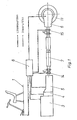
- FIG. 1 The basic illustration shown in FIG. 1 relates to a vehicle, of which only the steering position is shown.
- vehicle is labeled 1.
- engine 3 As components of the drive system of vehicle 1, engine 3 is shown with clutch 4 and manual transmission 5 connected directly to it.
- the cardan shaft 7 is connected to the gearbox flange 14 at the gearbox output of the gearbox 5. With its other end, the propeller shaft 7 is connected to the flange 15 of the axle drive 6, which serves to drive the wheel 11.
- the angle of rotation ⁇ of the cardan shaft 7 is measured between the two fixed points F1 and F2. The measurement is carried out using mechanical, permanent magnetic or optical sensors and measuring receivers. It is also possible to choose the phase shift of gears.
- the sensors work in such a way that in a certain position of the rotating and spatially fixed measuring device, the measuring signal, e.g. Magnetic field, light, electricity or space cams has a maximum.
- the measuring signal e.g. Magnetic field, light, electricity or space cams has a maximum.
- the shift of the maxima to each other is a measure of the angle of rotation.
- the determined measurement results are fed to an evaluation device 8, in which a difference is formed between the measured values and the predetermined values and it is determined whether the predetermined values are exceeded.
- the evaluation device 8 also serves to trigger certain switching processes, for example in such a way that the engine is throttled, the clutch is actuated to trigger a switching process in the transmission 5, or there is only an optical display which shows the operator that he is working in the limit range or already in the overload range.
- the measurement results and in particular the counting of the load cases lead, together with an evaluation device, to information about the remaining service life of individual components and are thus an indication of the maintenance and repair work required.
- the articulated shaft 7 consists of the two universal joints 26 and 27.
- Each of the two universal joints 26, 27 has an articulated fork 17 assigned to the intermediate shaft 19, as well as an articulated fork 18 provided with a flange 16.
- Each universal joint 26, 27 consists of a cross member 23, which has four pins 21 which are at right angles to one another and are supported in bearing bushes 24 which are received in bores in the flange fork 18 or driving fork 17.
- the bearing bushes 24 are secured in position in the bores of the associated joint yokes 17, 18 by means of retaining rings 25.
- the intermediate shaft 19 consists of a hub connected to the driving fork 17 of the universal joint 26, which has a toothed bore, and an intermediate tube 20 connected to the driving fork 17 of the universal joint 27 with an externally toothed pin 21 connected to it, which is displaceable in the toothed bore of the hub 22 , but is rotatably received.
- the two fork flanges 16 are associated with circumferential sensors 9a and 9b which cooperate with corresponding counter sensors 10a and 10b.
- the propeller shaft 7 is shown as if a moment was acting on it, ie the two flanges 16 are rotated relative to one another, so that the two pairs of sensors 9a, 10a and 9b and 10b determine an angle of rotation ⁇ .
- Figure 9 shows a typical diagram for a propeller shaft, in which the angle of rotation is shown on the vertical axis and the load torque on the horizontal axis. It can be seen that a proportional, linear rotation of the cardan shaft takes place over a considerable torque range. This linear range usually covers a twist angle of approximately 10 degrees. The curve then progresses.
- the PTO shaft as a sensor can be used for two tasks, namely as a sensor with digital information or as a sensor with analog information, ie a continuous function between the angle of rotation and the torque.
- the PTO shaft can be used as a transmitter with digital information in order to display load cycles above the elastic functional limit, for example as information for the driver or the workshop, or to count for a vehicle diagnostic system, for example.
- the PTO shaft can be used as a sensor with analogue information for measuring the respective torque value in the drive train. With the measured torque, a signal is then available that is an essential input variable for electronic drive management, that is, regulation of the engine, clutch and transmission.
- the torque measurement with the cardan shaft can also be used, for example, to measure the power split and also control the power split in self-propelled work equipment, for example wheel loaders, with regard to vehicle movement and bucket movement.
- the evaluation device can also be switched so that certain processes have priority. For example, the bucket movement should take precedence over the travel movement.
- the drawing figure 3 shows an arrangement of the propeller shaft 7, as shown in Fig. 2 in the drive system.
- the propeller shaft 7 is in turn shown between the drive unit consisting of motor 3, clutch 4 and gear 5 and the final drive 6.
- the rotating sensors 9a and 9b are assigned to the flanges 16 of the cardan shaft 7.
- the rotating sensors 9a and 9b are not assigned to the flanges of the cardan shaft 7, but rather to the flanges directly connected to them, namely the gear flange 14, which belongs to the output shaft of the gearbox 5, or the connecting flange 15 of the axle gear 6.
- the circumferential sensors 9a and 9b are assigned to the bottoms of the bearing bush of the propeller shaft. This assignment can be seen in more detail in the illustration according to FIG. 6. It can be seen that one of the bearing bushes 24 of each universal joint 26 and 27, which are in phase, are provided with a rotating sensor 9a and 9b. This sensor 9a or 9b can be part of the locking ring 25 for the bearing bush 24.
- the counter sensor 10a and 10b assigned to the rotating sensors 9a and 9b is also shown schematically.
- the counter sensors 10a, 10b there are various arrangement alternatives in a vehicle, for example a truck with body 2, which in principle are transferable to a passenger car.
- the counter sensors 10a and 10b are assigned to the sensors 9a and 9a. 7, the counter sensors are attached to the vehicle body 2.
- the gear 5 and the axle gear 6 are provided with special holders 12 and 13, to which the counter sensors 10 are fastened.
Priority Applications (3)
| Application Number | Priority Date | Filing Date | Title |
|---|---|---|---|
| EP88104403A EP0338095B1 (fr) | 1988-03-19 | 1988-03-19 | Dispositif pour mesurer des états de fonctionnement de systèmes de propulsion, surtout d'automobiles et d'appareils de travails automobiles |
| DE8888104403T DE3861723D1 (de) | 1988-03-19 | 1988-03-19 | Vorrichtung zum messen von betriebszustaenden in antriebssystemen, insbesondere von kraftfahrzeugen und selbstfahrenden arbeitsgeraeten. |
| AT88104403T ATE60662T1 (de) | 1988-03-19 | 1988-03-19 | Vorrichtung zum messen von betriebszustaenden in antriebssystemen, insbesondere von kraftfahrzeugen und selbstfahrenden arbeitsgeraeten. |
Applications Claiming Priority (1)
| Application Number | Priority Date | Filing Date | Title |
|---|---|---|---|
| EP88104403A EP0338095B1 (fr) | 1988-03-19 | 1988-03-19 | Dispositif pour mesurer des états de fonctionnement de systèmes de propulsion, surtout d'automobiles et d'appareils de travails automobiles |
Publications (2)
| Publication Number | Publication Date |
|---|---|
| EP0338095A1 true EP0338095A1 (fr) | 1989-10-25 |
| EP0338095B1 EP0338095B1 (fr) | 1991-01-30 |
Family
ID=8198819
Family Applications (1)
| Application Number | Title | Priority Date | Filing Date |
|---|---|---|---|
| EP88104403A Expired - Lifetime EP0338095B1 (fr) | 1988-03-19 | 1988-03-19 | Dispositif pour mesurer des états de fonctionnement de systèmes de propulsion, surtout d'automobiles et d'appareils de travails automobiles |
Country Status (3)
| Country | Link |
|---|---|
| EP (1) | EP0338095B1 (fr) |
| AT (1) | ATE60662T1 (fr) |
| DE (1) | DE3861723D1 (fr) |
Cited By (6)
| Publication number | Priority date | Publication date | Assignee | Title |
|---|---|---|---|---|
| FR2671589A1 (fr) * | 1991-01-14 | 1992-07-17 | Gkn Cardantec Int | Arbre de longueur variable muni d'un dispositif deformable indiquant une surcharge de couple de rotation. |
| WO2017155446A1 (fr) * | 2016-03-08 | 2017-09-14 | Scania Cv Ab | Dispositif de mesure permettant d'évaluer un paramètre de couple d'un véhicule et procédé d'évaluation d'un paramètre de couple d'un véhicule |
| EP3751163A1 (fr) * | 2019-06-14 | 2020-12-16 | Off-Highway Powertrain Services Germany GmbH | Arbre articulé |
| DE102019209157A1 (de) * | 2019-06-25 | 2020-12-31 | Zf Friedrichshafen Ag | Gelenkwellenanordnung |
| US11578762B2 (en) | 2019-02-15 | 2023-02-14 | Off-Highway Powertrain Services Germany GmbH | Journal cross and universal joint comprising the same |
| SE2250535A1 (en) * | 2022-05-03 | 2023-11-04 | Scania Cv Ab | Method and sensor arrangement for determining an adverse condition of a powertrain |
Citations (4)
| Publication number | Priority date | Publication date | Assignee | Title |
|---|---|---|---|---|
| US3871215A (en) * | 1971-05-10 | 1975-03-18 | Massachusetts Inst Technology | Opto-electronic apparatus to generate a pulse-modulated signal indicative of the mechanical state of a system |
| FR2275780A1 (fr) * | 1974-05-29 | 1976-01-16 | Torquemeters Ltd | Phasemetre, notamment applicable aux dispositifs torsiometriques, et procede pour sa mise en oeuvre |
| GB2095841A (en) * | 1981-03-31 | 1982-10-06 | Walterscheid Gmbh Jean | Measuring torque |
| EP0231665A1 (fr) * | 1985-12-27 | 1987-08-12 | Aisin-Warner Kabushiki Kaisha | Dispositif de commande pour véhicule à quatre roues motrices avec différentiel central |
-
1988
- 1988-03-19 EP EP88104403A patent/EP0338095B1/fr not_active Expired - Lifetime
- 1988-03-19 DE DE8888104403T patent/DE3861723D1/de not_active Expired - Lifetime
- 1988-03-19 AT AT88104403T patent/ATE60662T1/de not_active IP Right Cessation
Patent Citations (4)
| Publication number | Priority date | Publication date | Assignee | Title |
|---|---|---|---|---|
| US3871215A (en) * | 1971-05-10 | 1975-03-18 | Massachusetts Inst Technology | Opto-electronic apparatus to generate a pulse-modulated signal indicative of the mechanical state of a system |
| FR2275780A1 (fr) * | 1974-05-29 | 1976-01-16 | Torquemeters Ltd | Phasemetre, notamment applicable aux dispositifs torsiometriques, et procede pour sa mise en oeuvre |
| GB2095841A (en) * | 1981-03-31 | 1982-10-06 | Walterscheid Gmbh Jean | Measuring torque |
| EP0231665A1 (fr) * | 1985-12-27 | 1987-08-12 | Aisin-Warner Kabushiki Kaisha | Dispositif de commande pour véhicule à quatre roues motrices avec différentiel central |
Cited By (9)
| Publication number | Priority date | Publication date | Assignee | Title |
|---|---|---|---|---|
| FR2671589A1 (fr) * | 1991-01-14 | 1992-07-17 | Gkn Cardantec Int | Arbre de longueur variable muni d'un dispositif deformable indiquant une surcharge de couple de rotation. |
| WO2017155446A1 (fr) * | 2016-03-08 | 2017-09-14 | Scania Cv Ab | Dispositif de mesure permettant d'évaluer un paramètre de couple d'un véhicule et procédé d'évaluation d'un paramètre de couple d'un véhicule |
| US11578762B2 (en) | 2019-02-15 | 2023-02-14 | Off-Highway Powertrain Services Germany GmbH | Journal cross and universal joint comprising the same |
| EP3751163A1 (fr) * | 2019-06-14 | 2020-12-16 | Off-Highway Powertrain Services Germany GmbH | Arbre articulé |
| US11632014B2 (en) | 2019-06-14 | 2023-04-18 | Off-Highway Powertrain Services Germany GmbH | Joint shaft |
| DE102019209157A1 (de) * | 2019-06-25 | 2020-12-31 | Zf Friedrichshafen Ag | Gelenkwellenanordnung |
| SE2250535A1 (en) * | 2022-05-03 | 2023-11-04 | Scania Cv Ab | Method and sensor arrangement for determining an adverse condition of a powertrain |
| WO2023214914A1 (fr) * | 2022-05-03 | 2023-11-09 | Scania Cv Ab | Procédé et agencement de capteur pour déterminer une condition indésirable d'un groupe motopropulseur |
| SE545786C2 (en) * | 2022-05-03 | 2024-02-06 | Scania Cv Ab | Method and sensor arrangement for determining an adverse condition of a powertrain |
Also Published As
| Publication number | Publication date |
|---|---|
| ATE60662T1 (de) | 1991-02-15 |
| EP0338095B1 (fr) | 1991-01-30 |
| DE3861723D1 (de) | 1991-03-07 |
Similar Documents
| Publication | Publication Date | Title |
|---|---|---|
| DE102008001791B4 (de) | Getriebeeinheit mit translatorischem Freiheitsgrad | |
| DE3143723C2 (fr) | ||
| EP1596179A2 (fr) | Banc d'essai de véhicule | |
| DE10360582B4 (de) | Elektromechanische Lenkung eines Kraftfahrzeugs | |
| EP3381761A1 (fr) | Actionneur de commande d'un ensemble de roue d'un véhicule ferroviaire | |
| DE1480156A1 (de) | Kupplung zur UEbertragung von Drehbewegungen in Kraftfahrzeugen | |
| EP0338095B1 (fr) | Dispositif pour mesurer des états de fonctionnement de systèmes de propulsion, surtout d'automobiles et d'appareils de travails automobiles | |
| DE102006030143A1 (de) | Fahrzeug, insbesondere Allradfahrzeug, mit einer ersten lenkbaren Fahrzeugachse und einer zweiten lenkbaren Fahrzeugachse | |
| DE102017202507A1 (de) | Drehmomenterfassungseinrichtung, Antrieb und Arbeitsvorrichtung | |
| EP1843055A1 (fr) | Palier de roulement doté d'un capteur | |
| DE10225975B4 (de) | Verfahren zum Lenken eines Fahrzeugs und Lenkeinrichtung | |
| EP0634007B1 (fr) | Dispositif pour mesurer le couple dans un engrenage afin de transmettre un mouvement rotatif | |
| DE4208014C2 (de) | Straßensimulationsprüfstand für Fahrzeugachsen | |
| DE102019100323A1 (de) | Diagnose eines Verdrehspiels im Antriebsstrang | |
| EP3298871B1 (fr) | Machine agricole , procédé de détéction d'une charge mécanique sur un élément d' une machine agricole | |
| DE102017122289A1 (de) | Prüfstand zur Drehwiderstandsmessung | |
| EP0935129A2 (fr) | Roue de mesure à plusieurs composants | |
| DE102013019483A1 (de) | Verfahren und Vorrichtung zur Schwingungsdämpfung einer angetriebenen Achse mit Momentenquerverteilung | |
| DE19905325A1 (de) | Flurförderzeug mit zwei lenkbaren Antriebsrädern | |
| DE102014200861A1 (de) | Verfahren zur Schwingungsmessung einer mobilen Maschine | |
| DE102014208926A1 (de) | Ermittlungsvorrichtung zum Ermitteln eines Unterstützungsmomentes und Unterstützungsvorrichtung sowie Verfahren zum Unterstützen eines von einem Fahrer auf ein Lenksystem des Fahrzeugs aufgebrachten Lenkmomentes | |
| EP1122529A2 (fr) | Dispositif pour mesurer sur un arbre de transmission pour une roue de véhicule les nombres de tours et couples de même pour simuler l'état de conduite | |
| DE102019132437A1 (de) | Verfahren und Antriebssystem zur Schätzung von Gelenkwellenmomenten in Antriebssträngen | |
| DE10248833A1 (de) | Wellenstrang, insbesondere Gelenkwelle und homokinetischer Drehgestellantrieb für Schienenfahrzeuge | |
| DE102019209157A1 (de) | Gelenkwellenanordnung |
Legal Events
| Date | Code | Title | Description |
|---|---|---|---|
| PUAI | Public reference made under article 153(3) epc to a published international application that has entered the european phase |
Free format text: ORIGINAL CODE: 0009012 |
|
| AK | Designated contracting states |
Kind code of ref document: A1 Designated state(s): AT BE CH DE ES FR GB IT LI NL SE |
|
| 17P | Request for examination filed |
Effective date: 19891106 |
|
| 17Q | First examination report despatched |
Effective date: 19891220 |
|
| GRAA | (expected) grant |
Free format text: ORIGINAL CODE: 0009210 |
|
| STAA | Information on the status of an ep patent application or granted ep patent |
Free format text: STATUS: THE PATENT HAS BEEN GRANTED |
|
| AK | Designated contracting states |
Kind code of ref document: B1 Designated state(s): AT BE CH DE ES FR GB IT LI NL SE |
|
| ITF | It: translation for a ep patent filed |
Owner name: DE DOMINICIS & MAYER S.R.L. |
|
| PG25 | Lapsed in a contracting state [announced via postgrant information from national office to epo] |
Ref country code: GB Effective date: 19910130 Ref country code: ES Free format text: THE PATENT HAS BEEN ANNULLED BY A DECISION OF A NATIONAL AUTHORITY Effective date: 19910130 Ref country code: BE Effective date: 19910130 |
|
| REF | Corresponds to: |
Ref document number: 60662 Country of ref document: AT Date of ref document: 19910215 Kind code of ref document: T |
|
| REF | Corresponds to: |
Ref document number: 3861723 Country of ref document: DE Date of ref document: 19910307 |
|
| PG25 | Lapsed in a contracting state [announced via postgrant information from national office to epo] |
Ref country code: AT Effective date: 19910319 |
|
| PG25 | Lapsed in a contracting state [announced via postgrant information from national office to epo] |
Ref country code: LI Effective date: 19910331 Ref country code: CH Effective date: 19910331 |
|
| ET | Fr: translation filed | ||
| GBV | Gb: ep patent (uk) treated as always having been void in accordance with gb section 77(7)/1977 [no translation filed] | ||
| REG | Reference to a national code |
Ref country code: CH Ref legal event code: PL |
|
| PLBE | No opposition filed within time limit |
Free format text: ORIGINAL CODE: 0009261 |
|
| 26N | No opposition filed | ||
| EAL | Se: european patent in force in sweden |
Ref document number: 88104403.6 |
|
| PGFP | Annual fee paid to national office [announced via postgrant information from national office to epo] |
Ref country code: FR Payment date: 19950317 Year of fee payment: 8 |
|
| PGFP | Annual fee paid to national office [announced via postgrant information from national office to epo] |
Ref country code: SE Payment date: 19950324 Year of fee payment: 8 |
|
| PGFP | Annual fee paid to national office [announced via postgrant information from national office to epo] |
Ref country code: NL Payment date: 19950331 Year of fee payment: 8 |
|
| ITPR | It: changes in ownership of a european patent |
Owner name: FUSIONI;GKN AUTOMOTIVE AG |
|
| REG | Reference to a national code |
Ref country code: FR Ref legal event code: TP |
|
| NLS | Nl: assignments of ep-patents |
Owner name: GKN AUTOMOTIVE AG |
|
| PG25 | Lapsed in a contracting state [announced via postgrant information from national office to epo] |
Ref country code: SE Effective date: 19960320 |
|
| PG25 | Lapsed in a contracting state [announced via postgrant information from national office to epo] |
Ref country code: NL Effective date: 19961001 |
|
| PG25 | Lapsed in a contracting state [announced via postgrant information from national office to epo] |
Ref country code: FR Effective date: 19961129 |
|
| NLV4 | Nl: lapsed or anulled due to non-payment of the annual fee |
Effective date: 19961001 |
|
| EUG | Se: european patent has lapsed |
Ref document number: 88104403.6 |
|
| REG | Reference to a national code |
Ref country code: FR Ref legal event code: ST |
|
| PGFP | Annual fee paid to national office [announced via postgrant information from national office to epo] |
Ref country code: DE Payment date: 20010523 Year of fee payment: 14 |
|
| PG25 | Lapsed in a contracting state [announced via postgrant information from national office to epo] |
Ref country code: DE Free format text: LAPSE BECAUSE OF NON-PAYMENT OF DUE FEES Effective date: 20021001 |
|
| PG25 | Lapsed in a contracting state [announced via postgrant information from national office to epo] |
Ref country code: IT Free format text: LAPSE BECAUSE OF NON-PAYMENT OF DUE FEES;WARNING: LAPSES OF ITALIAN PATENTS WITH EFFECTIVE DATE BEFORE 2007 MAY HAVE OCCURRED AT ANY TIME BEFORE 2007. THE CORRECT EFFECTIVE DATE MAY BE DIFFERENT FROM THE ONE RECORDED. Effective date: 20050319 |