EP0337961A1 - Noeud d'assemblage pour structures spatiales à barres nervurées - Google Patents
Noeud d'assemblage pour structures spatiales à barres nervurées Download PDFInfo
- Publication number
- EP0337961A1 EP0337961A1 EP89830152A EP89830152A EP0337961A1 EP 0337961 A1 EP0337961 A1 EP 0337961A1 EP 89830152 A EP89830152 A EP 89830152A EP 89830152 A EP89830152 A EP 89830152A EP 0337961 A1 EP0337961 A1 EP 0337961A1
- Authority
- EP
- European Patent Office
- Prior art keywords
- rods
- nodal
- nodal element
- threaded
- profile
- Prior art date
- Legal status (The legal status is an assumption and is not a legal conclusion. Google has not performed a legal analysis and makes no representation as to the accuracy of the status listed.)
- Withdrawn
Links
- 238000005304 joining Methods 0.000 claims abstract description 8
- 239000007787 solid Substances 0.000 claims abstract description 7
- 230000000903 blocking effect Effects 0.000 claims abstract description 6
- 230000000295 complement effect Effects 0.000 claims description 6
- 229910052729 chemical element Inorganic materials 0.000 claims 1
- 230000006835 compression Effects 0.000 abstract description 4
- 238000007906 compression Methods 0.000 abstract description 4
- 229910000831 Steel Inorganic materials 0.000 abstract description 3
- 230000003068 static effect Effects 0.000 abstract description 3
- 239000010959 steel Substances 0.000 abstract description 3
- 230000006870 function Effects 0.000 abstract 1
- 230000009993 protective function Effects 0.000 abstract 1
- XAGFODPZIPBFFR-UHFFFAOYSA-N aluminium Chemical compound [Al] XAGFODPZIPBFFR-UHFFFAOYSA-N 0.000 description 4
- 229910052782 aluminium Inorganic materials 0.000 description 4
- 235000010210 aluminium Nutrition 0.000 description 4
- 239000004411 aluminium Substances 0.000 description 4
- HCHKCACWOHOZIP-UHFFFAOYSA-N Zinc Chemical compound [Zn] HCHKCACWOHOZIP-UHFFFAOYSA-N 0.000 description 3
- 239000011701 zinc Substances 0.000 description 3
- 229910052725 zinc Inorganic materials 0.000 description 3
- 238000011549 displacement method Methods 0.000 description 2
- 238000006073 displacement reaction Methods 0.000 description 2
- 238000009826 distribution Methods 0.000 description 2
- 239000011518 fibre cement Substances 0.000 description 2
- 238000000034 method Methods 0.000 description 2
- 230000002093 peripheral effect Effects 0.000 description 2
- 238000007792 addition Methods 0.000 description 1
- 230000015572 biosynthetic process Effects 0.000 description 1
- 238000004040 coloring Methods 0.000 description 1
- 230000007797 corrosion Effects 0.000 description 1
- 238000005260 corrosion Methods 0.000 description 1
- 238000005520 cutting process Methods 0.000 description 1
- 230000007547 defect Effects 0.000 description 1
- 239000011152 fibreglass Substances 0.000 description 1
- 239000003365 glass fiber Substances 0.000 description 1
- 230000000670 limiting effect Effects 0.000 description 1
- 238000004519 manufacturing process Methods 0.000 description 1
- 238000011017 operating method Methods 0.000 description 1
- 230000036961 partial effect Effects 0.000 description 1
- 238000007747 plating Methods 0.000 description 1
- 230000001681 protective effect Effects 0.000 description 1
- 230000002829 reductive effect Effects 0.000 description 1
- 230000000452 restraining effect Effects 0.000 description 1
- 229910001220 stainless steel Inorganic materials 0.000 description 1
- 239000010935 stainless steel Substances 0.000 description 1
- 238000003466 welding Methods 0.000 description 1
Images

Classifications
-
- F—MECHANICAL ENGINEERING; LIGHTING; HEATING; WEAPONS; BLASTING
- F16—ENGINEERING ELEMENTS AND UNITS; GENERAL MEASURES FOR PRODUCING AND MAINTAINING EFFECTIVE FUNCTIONING OF MACHINES OR INSTALLATIONS; THERMAL INSULATION IN GENERAL
- F16B—DEVICES FOR FASTENING OR SECURING CONSTRUCTIONAL ELEMENTS OR MACHINE PARTS TOGETHER, e.g. NAILS, BOLTS, CIRCLIPS, CLAMPS, CLIPS OR WEDGES; JOINTS OR JOINTING
- F16B7/00—Connections of rods or tubes, e.g. of non-circular section, mutually, including resilient connections
- F16B7/18—Connections of rods or tubes, e.g. of non-circular section, mutually, including resilient connections using screw-thread elements
- F16B7/185—Connections of rods or tubes, e.g. of non-circular section, mutually, including resilient connections using screw-thread elements with a node element
-
- E—FIXED CONSTRUCTIONS
- E04—BUILDING
- E04B—GENERAL BUILDING CONSTRUCTIONS; WALLS, e.g. PARTITIONS; ROOFS; FLOORS; CEILINGS; INSULATION OR OTHER PROTECTION OF BUILDINGS
- E04B1/00—Constructions in general; Structures which are not restricted either to walls, e.g. partitions, or floors or ceilings or roofs
- E04B1/18—Structures comprising elongated load-supporting parts, e.g. columns, girders, skeletons
- E04B1/19—Three-dimensional framework structures
- E04B1/1903—Connecting nodes specially adapted therefor
- E04B1/1906—Connecting nodes specially adapted therefor with central spherical, semispherical or polyhedral connecting element
-
- E—FIXED CONSTRUCTIONS
- E04—BUILDING
- E04B—GENERAL BUILDING CONSTRUCTIONS; WALLS, e.g. PARTITIONS; ROOFS; FLOORS; CEILINGS; INSULATION OR OTHER PROTECTION OF BUILDINGS
- E04B1/00—Constructions in general; Structures which are not restricted either to walls, e.g. partitions, or floors or ceilings or roofs
- E04B1/18—Structures comprising elongated load-supporting parts, e.g. columns, girders, skeletons
- E04B1/19—Three-dimensional framework structures
- E04B2001/1924—Struts specially adapted therefor
- E04B2001/1927—Struts specially adapted therefor of essentially circular cross section
-
- E—FIXED CONSTRUCTIONS
- E04—BUILDING
- E04B—GENERAL BUILDING CONSTRUCTIONS; WALLS, e.g. PARTITIONS; ROOFS; FLOORS; CEILINGS; INSULATION OR OTHER PROTECTION OF BUILDINGS
- E04B1/00—Constructions in general; Structures which are not restricted either to walls, e.g. partitions, or floors or ceilings or roofs
- E04B1/18—Structures comprising elongated load-supporting parts, e.g. columns, girders, skeletons
- E04B1/19—Three-dimensional framework structures
- E04B2001/1957—Details of connections between nodes and struts
- E04B2001/196—Screw connections with axis parallel to the main axis of the strut
-
- E—FIXED CONSTRUCTIONS
- E04—BUILDING
- E04B—GENERAL BUILDING CONSTRUCTIONS; WALLS, e.g. PARTITIONS; ROOFS; FLOORS; CEILINGS; INSULATION OR OTHER PROTECTION OF BUILDINGS
- E04B1/00—Constructions in general; Structures which are not restricted either to walls, e.g. partitions, or floors or ceilings or roofs
- E04B1/18—Structures comprising elongated load-supporting parts, e.g. columns, girders, skeletons
- E04B1/19—Three-dimensional framework structures
- E04B2001/1957—Details of connections between nodes and struts
- E04B2001/1972—Welded or glued connection
-
- E—FIXED CONSTRUCTIONS
- E04—BUILDING
- E04B—GENERAL BUILDING CONSTRUCTIONS; WALLS, e.g. PARTITIONS; ROOFS; FLOORS; CEILINGS; INSULATION OR OTHER PROTECTION OF BUILDINGS
- E04B1/00—Constructions in general; Structures which are not restricted either to walls, e.g. partitions, or floors or ceilings or roofs
- E04B1/18—Structures comprising elongated load-supporting parts, e.g. columns, girders, skeletons
- E04B1/19—Three-dimensional framework structures
- E04B2001/1981—Three-dimensional framework structures characterised by the grid type of the outer planes of the framework
- E04B2001/1984—Three-dimensional framework structures characterised by the grid type of the outer planes of the framework rectangular, e.g. square, grid
Definitions
- This invention relates to a nodal element for lattice spatial structures with ribbed profile rods, and also various assembly elements for completing the structure.
- Nodal elements can be simple welded sleeves, which may be connected by external threading to the rods, forming prefabricated pyramids with square bases, or consist of two hollow hemispheres joined by welding and reinforced by a circular disk onto which the rods are welded directly, or even knots with profiled channels into which the flattened ends of tubular rods are forced and then locked with bolted plates.
- One object of this invention is therefore that of supplying a lattice spatial structure, and its nodal elements in particular, such as to overcome the aforementioned technical problems by the use of continuous ribbed rods available in any length by cutting according to the size.
- a spherical nodal element consisting of two substantially solid hemispheres, flanged across a diametral plane through and able to be screwed together through the flanges, each formed with two impressions at right angles to each other, adapted to form when screwed together the support housings for two concurrent ribbed rods, crossing and superimposed upon each other, in correspondence with the centre of the sphere, from opposite positions relative to said diametral plane, the said sphere in addition having on at least one hemisphere several threaded blind radial holes for fixing the ends of diagonal ribbed rods by means of stud bolts, using double threaded connecting sleeves.
- said continuous ribbed rods are formed of pseudo-threaded bars, in articular of the type known as "DYWIDAG” or "GEWI".
- the seats formed within the spherical knot have threaded surfaces for blocking the stringers.
- the bars need not be necessarily limited to this type of ribbing, which can instead be of any type, in a longitudinal, circumferential or radial direction, and even obtained by notching or channelling in the profile of the said bars. According to this invention they simply must not be smooth and the right angled, superimposed impressions in the spheres will have a complementary shape to that of the bars so as to block them by restaint.
- tubular coverings of the stringers or main rods which possibly should they be stressed with compression, give their contribution in reacting to the assigned forces, since they are preferably formed of coaxial tubular elements with the rods themselves to which they are fixed by header flanges located on the rods in proximity of the knot by joining and blocking sleeves.
- Said tubular elements are preferably in steel, either zinc plated or stainless, aluminium or glass fibre. Should they not be required to fulfil a mechanical support operation but merely a covering function of aesthetic or protective nature or even assimilable as to the function of a template to check the free lengths of the rods, said tubular elements can be, for example, of aluminium, rigid PVC or fibre-cement.
- planar lattice spatial structures may be obtained whose links(of triangular, square, rectangular shape etc.) are provided with the characteristics of stringer continuity, both upper and lower, without the intervention of nodal interruptions.
- the spherical knots do not interrupt the continuity of the bars which form the virtual stringers, but have the sole function of junction pseudo-sleeves into which converge the truncated bars of the diagonal rods, thus forming the lattice structure.
- the nodal elements according to this invention give rise to a displacement of the stringers or main rods owing to the superimposition of these in correspondence of the knots. Since in spatial structures the nodal behaviour should be that of balancing the forces transmitted by the rods directed to the centre of the knot by means of the "knots displacement method", in the calculation procedure for the determination of forces, account will be thus taken of the displacement of stringers by redirecting the forces from their "virtual centre” to the "knot centre”. Thus the so-called knot “displacement method” will be adopted, also noting for each of them the relevant equations for "balance of moments", according to this invention, due to the superimposed cross-over conditions of the stringers at the knots.
- the fundamental element for obtaining the structure according to this invention is the knot 1 formed of the two solid hemispheres 1a and 1b having, in correspondence with the diameter, a flange 2 for joining the two hemispheres together using screws through the holes 3 provided in said flanges.
- Two seats with a U-shaped cross-section, at right angles to each other and superimposed are formed, respectively recessed and upraised with respect to said flange, so that, on joining together the two hemispheres, two crossing tracked channels at different levels for blocking the junction of the continuous ribbed rods 10.
- These are made of high resistance steel bars, possibly with electrolytic zinc plating, and having surface ribbing, preferably in the form of long pitch pseudo-threading.
- the seats 4 and 4′ will have a right or left handed pseudo-thread complementary to that of the bars for their jointing.
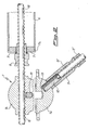
- Fig. 2 In the upper part of Fig. 2 is shown a cross-section taken along the plane A-A shown in Fig. 1 perpendicular to flange 2 and passing through the axis of seat 4. In the lower part of the same Fig. 2 is shown a partial cross-section of the knot, taken along the plane B-B, also shown in Fig. 1, which intersects flange 2 perpendicularly along one of its diagonals.
- the crossover of the two rods superimposed on each other is clearly seen in correspondence with the equatorial plane of the sphere 1 so as to have their nearest approach point corresponding to the centre of the said sphere.
- Rods 10 have been shown as being of the "DYWIDAG” or “GEWI” type, but naturally they could be formed with a different type of ribbing and in this case seats 4 and 4′ will show patterns of a complementary shape to said ribbing which, in general, can be of any type, having either projections or cavities which are repeated periodically in a uniform way on the surface.
- Fig. 2 also shows around one of the two longitudinal stringers 10, and specifically the one parallel to the plane of the sheet, a tubular element 6, applied coaxially to the bar itself to which it is fixed by two header flanges 7, one of which can be seen in the figure with a peripheral lip 7a for restraining the tubular profile and with a central hole for the passage of the rod, as well as for locking a connecting sleeve 8.
- This latter is shaped towards the inner end of the tubular element with a centring taper for the hole in flange 7 and has an internal impression complementary to the ribbing of rod 10.
- the sleeve 8 will be made with long pitch internal pseudo-threading and will thus be an accessory element supplied with the bars themselves. However, for ease of assembly, it will preferably consist of two half sleeves locked together by a circlip or split washer.
- tubular elements 6, in zinc plated or stainless steel, aluminium or fibre glass will be assembled to the continuous rod 10 above all where a compression stress is envisaged, which can be determined beforehand by calculations, as has been stated above.
- optional coverings for the rods can be provided in aluminium, rigid PVC and fibre cement having the same tubular shape and the function of protecting the bars against corrosion or fire, or with the simple aesthetic task of hiding the ribbing of the bars and to provide the desired colouring, although in this case spirally wound filiform coverings, around the bars and adhering to the ribbing, could be adopted.
- Tubular elements can also be used with the function of a template as a check of the free lengths of the rods themselves.
- truncated bars 10′ which provide for the diagonal rods
- truncated bars 10′ which provide for the diagonal rods
- the bars 10′ will have the same peripheral ribbing as the rods 10, in particular pseudo-threading of the "DYWIDAG” or "GEWI” type, but they could also have a smaller cross-section than these latter.
- a connecting sleeve 11 for connecting the end of the truncated bar 10′ to the nodal sphere.
- the rod sleeve 11 will be double threaded (normal for the screwing in of a stud bolt 12, to be tightened into a threaded blind hole 13 provided in one of the solid hemispheres, and with pseudo-threading in the section to be fixed at the end of the rod 10′).
- a sleeve 11 of this type and relative lock-nut 11′ are normally provided with a supply of "DYWIDAG” or "GEWI" rods.
- the sleeves 11 will also have an adequate internal pattern, complementary to the ribbing of the rods, and may also, like the covers 8, be formed in two halves which may be blocked around the said rod.
- Each hemisphere 1a, 1b will have a certain number of radial threaded holes 13 of which only one has been shown in the figure, and this number will preferably be the maximum compatible with the structural integrity of the sphere, as a function of its size and of the diameter of each hole 13.
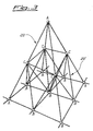
- this shows a link or loop of a semi-octahedron shape 20 built by using the structural elements of this invention and having its apexes in the knots A.
- the sleeves 11 can in addition be used to control the length of the diagonal rods. Control is always by retraction and as a first step the theoretical length of the rod is determined which is then inserted during the initial phase of assembly as shortened, while subsequently the sleeves are tightened until reaching the required lenght. This makes it possible to insert diagonal bars into multi-layer spatial structural systems. On the other hand the speed and ease of assembly of stringers of continuous type is obvious in such a way that the pseudo-rods are a consequence of their modular distribution.
- the assembly of the lattice structure obtained with the elements described above should preferably be carried out with the following operating methods, reported by way of an example.
- First of all the continuous ribbed bars used for the stringers are laid out on the ground, in crossed positions in the places determined by the free lengths of the rods, obtained by calculation and reproduced, for example, with the aid of dimensional templates or by using tubular rod coverings, as previously described, for this purpose.
- the envisaged sub-pyramids can then be provided, with a halving of the free deflection lengths of the rods, as illustrated in Fig. 3.
- the tubular rods will have been assembled onto the compressed bars, with their relative header flanges and the junction sleeves of the same pattern as the profile of the rod, or alternatively, the simple covering tubular elements.
- a fundamental characteristic of the system is the continuity of the upper and lower stringers of the links of plane structures, which are thus implemented according to the real, literal concept of the word, that is without continuous solutions in correspondence with the knot, where on the other hand, they cross over with superimposition creating "knots with virtual centres”.
Landscapes
- Engineering & Computer Science (AREA)
- General Engineering & Computer Science (AREA)
- Architecture (AREA)
- Mechanical Engineering (AREA)
- Physics & Mathematics (AREA)
- Electromagnetism (AREA)
- Civil Engineering (AREA)
- Structural Engineering (AREA)
- Joining Of Building Structures In Genera (AREA)
Applications Claiming Priority (2)
| Application Number | Priority Date | Filing Date | Title |
|---|---|---|---|
| IT8820142A IT8820142A0 (it) | 1988-04-08 | 1988-04-08 | Elemento nodale per strutture reticolari spaziali con aste a profilo nervato. |
| IT2014288 | 1988-04-08 |
Publications (1)
| Publication Number | Publication Date |
|---|---|
| EP0337961A1 true EP0337961A1 (fr) | 1989-10-18 |
Family
ID=11164143
Family Applications (1)
| Application Number | Title | Priority Date | Filing Date |
|---|---|---|---|
| EP89830152A Withdrawn EP0337961A1 (fr) | 1988-04-08 | 1989-04-07 | Noeud d'assemblage pour structures spatiales à barres nervurées |
Country Status (2)
| Country | Link |
|---|---|
| EP (1) | EP0337961A1 (fr) |
| IT (1) | IT8820142A0 (fr) |
Cited By (2)
| Publication number | Priority date | Publication date | Assignee | Title |
|---|---|---|---|---|
| WO2006097545A1 (fr) * | 2005-03-16 | 2006-09-21 | Montur Estan, S.L. | Noeud pour structures reticulaires |
| WO2016138912A1 (fr) | 2015-03-02 | 2016-09-09 | Al-Tuhami Al-Tuhami Abuzeid | Renfort d'armature et ses joints de coupleur mécaniques pour utilisation de béton de construction |
Families Citing this family (1)
| Publication number | Priority date | Publication date | Assignee | Title |
|---|---|---|---|---|
| CN114033032A (zh) * | 2021-12-13 | 2022-02-11 | 中国铁路武汉局集团有限公司武汉房建生活段 | 一种火车站站房钢结构网架 |
Citations (5)
| Publication number | Priority date | Publication date | Assignee | Title |
|---|---|---|---|---|
| GB704758A (en) * | 1950-06-22 | 1954-03-03 | Victor Francis Pym | An improved structural element and a method of using said structural element in building |
| FR86183E (fr) * | 1964-07-24 | 1965-12-24 | Ferrotest G M B H | Elément d'armature pour constructions en béton armé |
| US3864049A (en) * | 1973-01-11 | 1975-02-04 | Taisaburo Ono | Construction elements of underwater trusses |
| BE823969A (fr) * | 1974-12-30 | 1975-04-16 | Systeme de construction de structures spatiales | |
| GB2197417A (en) * | 1986-10-20 | 1988-05-18 | Lawrence Paul | Space frame joint |
-
1988
- 1988-04-08 IT IT8820142A patent/IT8820142A0/it unknown
-
1989
- 1989-04-07 EP EP89830152A patent/EP0337961A1/fr not_active Withdrawn
Patent Citations (5)
| Publication number | Priority date | Publication date | Assignee | Title |
|---|---|---|---|---|
| GB704758A (en) * | 1950-06-22 | 1954-03-03 | Victor Francis Pym | An improved structural element and a method of using said structural element in building |
| FR86183E (fr) * | 1964-07-24 | 1965-12-24 | Ferrotest G M B H | Elément d'armature pour constructions en béton armé |
| US3864049A (en) * | 1973-01-11 | 1975-02-04 | Taisaburo Ono | Construction elements of underwater trusses |
| BE823969A (fr) * | 1974-12-30 | 1975-04-16 | Systeme de construction de structures spatiales | |
| GB2197417A (en) * | 1986-10-20 | 1988-05-18 | Lawrence Paul | Space frame joint |
Cited By (2)
| Publication number | Priority date | Publication date | Assignee | Title |
|---|---|---|---|---|
| WO2006097545A1 (fr) * | 2005-03-16 | 2006-09-21 | Montur Estan, S.L. | Noeud pour structures reticulaires |
| WO2016138912A1 (fr) | 2015-03-02 | 2016-09-09 | Al-Tuhami Al-Tuhami Abuzeid | Renfort d'armature et ses joints de coupleur mécaniques pour utilisation de béton de construction |
Also Published As
| Publication number | Publication date |
|---|---|
| IT8820142A0 (it) | 1988-04-08 |
Similar Documents
| Publication | Publication Date | Title |
|---|---|---|
| US3415552A (en) | Splicing metallic reinforcing rods with a threaded coupling sleeve | |
| US5956917A (en) | Co-axial joint system | |
| US4974986A (en) | Connector for variable-shape spaceframe structural system | |
| CA1062436A (fr) | Dispositif pour l'assemblage d'elements mecaniques | |
| US6887009B1 (en) | Cylindrical joint and reticulated frame structure | |
| CN107724585B (zh) | 一种开口式超大跨度索穹顶结构 | |
| JPH08509275A (ja) | 送電塔及びその他の大型構造物のための引出成形複合物継手システム | |
| KR980701061A (ko) | 모르타르 충전식 철근 조인트(Mortar Filling type Reinforcement Joint) | |
| US5412843A (en) | Hinge connector | |
| CZ333795A3 (en) | Device for connecting structural elements | |
| US6056085A (en) | Anchorage methods and apparatus | |
| EP0337961A1 (fr) | Noeud d'assemblage pour structures spatiales à barres nervurées | |
| CA1272575A (fr) | Raccord d'elements d'une structure en forme de resille | |
| US5797234A (en) | Flexible connector and assembly for structural connection | |
| HU229328B1 (hu) | Csatlakozóperemmel ellátott flexibilis tömlõ és eljárás ilyen tömlõ elõállítására | |
| NZ205541A (en) | Space frame: reinforcement plug and shaped washers at brace/node joints | |
| EP1865209A1 (fr) | Noeud pour structures reticulaires | |
| US6009914A (en) | Tube compression limiting apparatus and method | |
| DE4126825C1 (en) | Front shuttering securing for facade subsequent repair - drills circular groove in supports shuttering for retaining cylindrical jacket of securing member | |
| US5353503A (en) | Method of providing a fire-proof and/or wear resistant lining | |
| US4863303A (en) | Structural joint members for space frame system | |
| CA1215516A (fr) | Element d'armature | |
| WO2020016164A1 (fr) | Nœud de ramification de charge avec angle de sortie réglable | |
| EP1200683A1 (fr) | Systeme de jonction coaxiale | |
| CN114000596A (zh) | 混凝土梁端与曲面剪力墙施工缝处理装置及方法 |
Legal Events
| Date | Code | Title | Description |
|---|---|---|---|
| PUAI | Public reference made under article 153(3) epc to a published international application that has entered the european phase |
Free format text: ORIGINAL CODE: 0009012 |
|
| AK | Designated contracting states |
Kind code of ref document: A1 Designated state(s): AT BE CH DE ES FR GB GR LI LU NL SE |
|
| RIN1 | Information on inventor provided before grant (corrected) |
Inventor name: SPINELLI,ALBERTO |
|
| STAA | Information on the status of an ep patent application or granted ep patent |
Free format text: STATUS: THE APPLICATION IS DEEMED TO BE WITHDRAWN |
|
| 18D | Application deemed to be withdrawn |
Effective date: 19900419 |