EP0337900A1 - Elektromagnetischer Auslöser mit hoher Empfindlichkeit - Google Patents
Elektromagnetischer Auslöser mit hoher Empfindlichkeit Download PDFInfo
- Publication number
- EP0337900A1 EP0337900A1 EP89420102A EP89420102A EP0337900A1 EP 0337900 A1 EP0337900 A1 EP 0337900A1 EP 89420102 A EP89420102 A EP 89420102A EP 89420102 A EP89420102 A EP 89420102A EP 0337900 A1 EP0337900 A1 EP 0337900A1
- Authority
- EP
- European Patent Office
- Prior art keywords
- base
- trip device
- cover
- electromagnetic trip
- carcass
- Prior art date
- Legal status (The legal status is an assumption and is not a legal conclusion. Google has not performed a legal analysis and makes no representation as to the accuracy of the status listed.)
- Granted
Links
Images

Classifications
-
- H—ELECTRICITY
- H01—ELECTRIC ELEMENTS
- H01H—ELECTRIC SWITCHES; RELAYS; SELECTORS; EMERGENCY PROTECTIVE DEVICES
- H01H71/00—Details of the protective switches or relays covered by groups H01H73/00 - H01H83/00
- H01H71/10—Operating or release mechanisms
- H01H71/12—Automatic release mechanisms with or without manual release
- H01H71/24—Electromagnetic mechanisms
- H01H71/32—Electromagnetic mechanisms having permanently magnetised part
- H01H71/325—Housings, assembly or disposition of different elements in the housing
-
- H—ELECTRICITY
- H01—ELECTRIC ELEMENTS
- H01H—ELECTRIC SWITCHES; RELAYS; SELECTORS; EMERGENCY PROTECTIVE DEVICES
- H01H51/00—Electromagnetic relays
- H01H51/22—Polarised relays
- H01H51/2236—Polarised relays comprising pivotable armature, pivoting at extremity or bending point of armature
-
- H—ELECTRICITY
- H01—ELECTRIC ELEMENTS
- H01H—ELECTRIC SWITCHES; RELAYS; SELECTORS; EMERGENCY PROTECTIVE DEVICES
- H01H71/00—Details of the protective switches or relays covered by groups H01H73/00 - H01H83/00
- H01H71/02—Housings; Casings; Bases; Mountings
- H01H71/0207—Mounting or assembling the different parts of the circuit breaker
- H01H2071/0242—Assembling parts of a circuit breaker by using snap mounting techniques
Definitions
- the invention relates to an electromagnetic trip device with magnetic latching, in particular for a differential switch or circuit breaker, having an insulating housing consisting of a base and an open bottom cover snapping onto the base to form a closed housing. , inside which are housed a U-shaped frame, the ends of the two legs of which constitute two coplanar pole surfaces and the base of which is held in abutment with the base, a pivoting pallet coming in the armed position of the release device to stick on said said two pole surfaces for closing the magnetic circuit formed by the armature and the paddle, a permanent magnet for polarizing the magnetic circuit and a trip coil surrounding the magnetic circuit and having a carcass with a lower face attached to the base of the armature.
- the manufacture and mounting of very high sensitivity electromagnetic trip devices of the kind mentioned must be particularly careful in order to obtain high trigger accuracy.
- the object of the present invention is to produce a simplified trip device the mounting of which is easier and is likely to be partially or fully automated.
- the electromagnetic trip device is characterized in that said base and said lower face of the carcass have latching means and that the cover has bosses coming to bear on the upper face of the carcass during installation of the cover to position and lock the frame, the pallet and the carcass inside the housing, the base of the frame being wedged between the base and the underside of the carcass.
- the trigger elements are fixed on the one hand by the snap-fastening of the coil carcass on the base and on the other hand by the support of the cover on this carcass. Locking by the cover ensures proper fixing and positioning of the trigger elements inside the housing.
- This fixing is effected by simple snaps which can be carried out by automatic assembly machines.
- the cover has a parallelepiped shape with means for fixing the trigger.
- One of the fixing means is constituted by a beveled angle of the upper face allowing to remain on the edges, two perforated ears allowing the passage of a fixing axis.
- the two angles are preferably bevelled for fixing by the two edges of the upper face of the cover.
- the cover advantageously has additional fixing means constituted by lugs carried by the small side faces in a manner well known to specialists.
- the two large side faces of the cover may have steps for fixing by snap-fastening to secure the trigger to a support carrying snap-on spouts.
- the return spring is anchored at one of its ends by an adjustment screw screwed into the turns of the spring.
- the screw performs the dual function of holding and adjusting the spring return force.
- the head of the adjustment screw is supported on a lug secured to the frame of the trigger by inserting into a notch formed in this lug.
- the very high sensitivity relay boxes must be dust-tight and according to a development of the invention, the snap-on lugs of the base on the cover are shaped to close the openings in which these lugs engage.
- the orifices are advantageously circular in shape and the ends of the spouts are in the form of cylindrical pegs which snap into these orifices.
- the permanent magnet for biasing the armature is disposed between the legs of this armature and is held by the carcass of the coil which for this purpose has extensions provided with cutouts through which the permanent magnet passes.
- the assembly is particularly simple and the assembly is carried out by simple stacking and snap-fastening of the parts one on the other.
- the cover and the base are advantageously made of plastic material loaded with magnetic particles, in particular iron, to form a magnetic screen against external disturbances.
- This magnetic protection can be reinforced or produced by an external magnetic screen, which fits, for example, on the cover and the base.
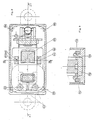
- the magnetic circuit of a high-sensitivity electromagnetic trip device consists of a U-shaped frame 10 and a pivoting pallet 12.
- the pallet 12 is articulated on the end of one of the legs 14, 16 of the frame 10 and in the armed position of the trigger, the pallet 12 is applied to the ends of the legs 14, 16 constituting two polar surfaces.
- On the branch 16 of the frame 10 is threaded a carcass 18 of a coil 20.
- a permanent magnet 22 for polarizing the frame 10 is interposed between the legs 14, 16 to maintain the pallet 12 in the position attracted to the 'against the return force of a coil spring 24.
- the assembly is housed inside a housing constituted by a base 26 and a cover 28 covering the base 26. The upper face of the cover 28 is crossed by a control pin 30 bearing on the pallet 12.
- Such a trigger is well known and it suffices to recall that the release of the pallet is caused by an excitation of the coil 20 canceling the attraction of the pallet 12 by the permanent magnet 22.
- the coil 20 is surrounded by lower 32 and upper 34 flanges of the carcass 18, these flanges being extended to form support elements for the permanent magnet 22 which passes through orifices 36, 38, formed in the extensions of these flanges 32 , 34.
- the underside of the flange 32 is supported on the base of the frame 10 and has two slots 46, 48 in which engage snap-on spouts 42, 44 carried by the base 26.
- the carcass 18 maintains the base of the frame 10 in support of the base 26 and positions the permanent magnet 22.
- the cover 28 fits onto the base 26 by snapping onto four spouts 50 formed at the four angles of the rectangular base.
- the upper face of the base 28 carries internal bosses 52 which come to bear on the upper flange 34 of the carcass 18 in the snap-on position of the cover, to lock this carcass on the base 26.
- the carcass 18 also carries centering pins 54 s 'engaging in conjugate holes in the base 26.
- the return spring 24 is a coil tension spring, one of the ends 56 of which is anchored to the pallet 12 and the other end of which 58 is anchored by an adjustment screw 60 to a lug 62 secured to the frame 10
- the screw 60 is engaged in a notch 64 of the lug 62, the head 66 of the screw 60 resting on the edges of this notch 64 and the threaded part of the screw 60 both screwed into the turns of the spring 24.
- the adjustment is effected by a rotation of the head 66 causing the threaded part of the screw 60 to penetrate into the spring 24.
- the base 26 has, opposite the head 66, an orifice 68 for access to the screw 60.
- the cover 28 of generally parallelepiped shape has on its two small side faces 70, 72 of the fixing lugs perforated 74, 76, allowing the support of the trigger and the fixing by screws crossing the legs 74, 76.
- the upper angles of the small lateral faces 70, 72, have bevels 78, 80 which leave lateral extensions in the form of ears 82, 84 perforated with holes 86 allowing the passage of a fixing pin (not shown).
- the cover 28 comprises a third fixing means constituted by conjugate steps of the bosses 52.
- the ends of the snap-fit lugs 50 carried by the base 26 have a rounded shape engaging and closing off circular orifices provided in the cover 28. This shape of the snap-fit spouts contributes to the tightness of the housing by limiting the penetration of dust or other impurities.
- the base 26 carries two pins 87 to which the wires of the coil 20 are welded.
- the mounting of the trigger according to the invention is particularly simple.
- This assembly is secured to the base 26 by simple snap-fitting of the spouts 42, 44, into the slots 46, 48 taking care to correctly position the centering pins 54.
- This snap-fastening fixes the elements of the trigger to the rigid base 26 while allowing access to the adjustment screw 66 through the orifice 68 of the base.
- the cover 28 is fitted and snapped onto the base 26 and the bosses 52 come to bear on the carcass 18 to lock the latter.
- the housing can be fixed to a support, for example to a differential circuit breaker, either by the lateral tabs 74, 76, or by the axes passing through the perforated ears 82, 84, or by a snap-fastening on the steps opposite the bosses 52.
- the different housing fixing means can be used separately or in combination.
Landscapes
- Physics & Mathematics (AREA)
- Electromagnetism (AREA)
- Breakers (AREA)
- Medicines Containing Antibodies Or Antigens For Use As Internal Diagnostic Agents (AREA)
- Measuring Instrument Details And Bridges, And Automatic Balancing Devices (AREA)
- Fire-Detection Mechanisms (AREA)
- Shielding Devices Or Components To Electric Or Magnetic Fields (AREA)
- Magnetic Treatment Devices (AREA)
Applications Claiming Priority (2)
| Application Number | Priority Date | Filing Date | Title |
|---|---|---|---|
| FR8805063A FR2630256B1 (fr) | 1988-04-14 | 1988-04-14 | Declencheur electromagnetique a haute sensibilite |
| FR8805063 | 1988-04-14 |
Publications (2)
| Publication Number | Publication Date |
|---|---|
| EP0337900A1 true EP0337900A1 (de) | 1989-10-18 |
| EP0337900B1 EP0337900B1 (de) | 1994-06-01 |
Family
ID=9365375
Family Applications (1)
| Application Number | Title | Priority Date | Filing Date |
|---|---|---|---|
| EP89420102A Expired - Lifetime EP0337900B1 (de) | 1988-04-14 | 1989-03-23 | Elektromagnetischer Auslöser mit hoher Empfindlichkeit |
Country Status (5)
| Country | Link |
|---|---|
| EP (1) | EP0337900B1 (de) |
| AT (1) | ATE106604T1 (de) |
| DE (1) | DE68915607T2 (de) |
| ES (1) | ES2057169T3 (de) |
| FR (1) | FR2630256B1 (de) |
Cited By (8)
| Publication number | Priority date | Publication date | Assignee | Title |
|---|---|---|---|---|
| EP0508052A3 (en) * | 1991-04-07 | 1993-08-11 | Schiele Gmbh & Co Kg | Fault current relay |
| EP0575980A1 (de) * | 1992-06-25 | 1993-12-29 | ABB Elettrocondutture S.p.A. | Polarisierte elektromagnetische Betätigungsvorrichtung |
| EP0840343A1 (de) * | 1996-11-05 | 1998-05-06 | Holec Holland N.V. | Steuereinheit für einen elektrischen Schalter und Verfahren zu seiner Herstellung |
| EP1248277A1 (de) * | 2001-04-06 | 2002-10-09 | SERD Société d'Etude et de Réalisation de Disjoncteurs | Elektromagnetischer Auslöser mit einer flexiblen Trägereinrichtung für einen elektromagnetischen Kreis und einen elektromagnetischen Auslöser mit einer schwebenden Spule |
| EP1248278A1 (de) * | 2001-04-06 | 2002-10-09 | SERD Société d'Etude et de Réalisation de Disjoncteurs | Elektromagnetischer Auslöser mit einem elektromagnetischen Kreis und mit einem Anker mit drei stabilen Positionen |
| FR2823370A1 (fr) * | 2001-04-06 | 2002-10-11 | Realisation De Disjoncteurs So | Declencheur electromagnetique comprenant une armature mobile et une armature fixe sur laquelle est encliquetee une piece de guidage de l'armature mobile |
| US6919785B2 (en) | 2000-05-16 | 2005-07-19 | General Electric Company | Pressure sensitive trip mechanism for a rotary breaker |
| US6995640B2 (en) | 2000-05-16 | 2006-02-07 | General Electric Company | Pressure sensitive trip mechanism for circuit breakers |
Families Citing this family (71)
| Publication number | Priority date | Publication date | Assignee | Title |
|---|---|---|---|---|
| IT1292453B1 (it) | 1997-07-02 | 1999-02-08 | Aeg Niederspannungstech Gmbh | Gruppo rotante di contatti per interrutttori di alta portata |
| DE19819242B4 (de) | 1998-04-29 | 2005-11-10 | Ge Power Controls Polska Sp.Z.O.O. | Thermomagnetischer Leistungsschalter |
| US6114641A (en) | 1998-05-29 | 2000-09-05 | General Electric Company | Rotary contact assembly for high ampere-rated circuit breakers |
| US6087913A (en) | 1998-11-20 | 2000-07-11 | General Electric Company | Circuit breaker mechanism for a rotary contact system |
| US6037555A (en) | 1999-01-05 | 2000-03-14 | General Electric Company | Rotary contact circuit breaker venting arrangement including current transformer |
| US6166344A (en) | 1999-03-23 | 2000-12-26 | General Electric Company | Circuit breaker handle block |
| US6262872B1 (en) | 1999-06-03 | 2001-07-17 | General Electric Company | Electronic trip unit with user-adjustable sensitivity to current spikes |
| US6268991B1 (en) | 1999-06-25 | 2001-07-31 | General Electric Company | Method and arrangement for customizing electronic circuit interrupters |
| US6218917B1 (en) | 1999-07-02 | 2001-04-17 | General Electric Company | Method and arrangement for calibration of circuit breaker thermal trip unit |
| US6188036B1 (en) | 1999-08-03 | 2001-02-13 | General Electric Company | Bottom vented circuit breaker capable of top down assembly onto equipment |
| US6710988B1 (en) | 1999-08-17 | 2004-03-23 | General Electric Company | Small-sized industrial rated electric motor starter switch unit |
| US6252365B1 (en) | 1999-08-17 | 2001-06-26 | General Electric Company | Breaker/starter with auto-configurable trip unit |
| US6175288B1 (en) | 1999-08-27 | 2001-01-16 | General Electric Company | Supplemental trip unit for rotary circuit interrupters |
| US6396369B1 (en) | 1999-08-27 | 2002-05-28 | General Electric Company | Rotary contact assembly for high ampere-rated circuit breakers |
| US6232570B1 (en) | 1999-09-16 | 2001-05-15 | General Electric Company | Arcing contact arrangement |
| US6326869B1 (en) | 1999-09-23 | 2001-12-04 | General Electric Company | Clapper armature system for a circuit breaker |
| US6239395B1 (en) | 1999-10-14 | 2001-05-29 | General Electric Company | Auxiliary position switch assembly for a circuit breaker |
| US6229413B1 (en) | 1999-10-19 | 2001-05-08 | General Electric Company | Support of stationary conductors for a circuit breaker |
| US6317018B1 (en) | 1999-10-26 | 2001-11-13 | General Electric Company | Circuit breaker mechanism |
| US6232856B1 (en) | 1999-11-02 | 2001-05-15 | General Electric Company | Magnetic shunt assembly |
| US6377144B1 (en) | 1999-11-03 | 2002-04-23 | General Electric Company | Molded case circuit breaker base and mid-cover assembly |
| ES2249875T3 (es) | 1999-11-03 | 2006-04-01 | AEG NIEDERSPANNUNGSTECHNIK GMBH & CO. KG | Disposicion de brazo de contacto rotatorio para disyuntor. |
| US6300586B1 (en) | 1999-12-09 | 2001-10-09 | General Electric Company | Arc runner retaining feature |
| US6310307B1 (en) | 1999-12-17 | 2001-10-30 | General Electric Company | Circuit breaker rotary contact arm arrangement |
| US6172584B1 (en) | 1999-12-20 | 2001-01-09 | General Electric Company | Circuit breaker accessory reset system |
| US6184761B1 (en) | 1999-12-20 | 2001-02-06 | General Electric Company | Circuit breaker rotary contact arrangement |
| US6215379B1 (en) | 1999-12-23 | 2001-04-10 | General Electric Company | Shunt for indirectly heated bimetallic strip |
| US6281461B1 (en) | 1999-12-27 | 2001-08-28 | General Electric Company | Circuit breaker rotor assembly having arc prevention structure |
| US6346869B1 (en) | 1999-12-28 | 2002-02-12 | General Electric Company | Rating plug for circuit breakers |
| US6211758B1 (en) | 2000-01-11 | 2001-04-03 | General Electric Company | Circuit breaker accessory gap control mechanism |
| US6239677B1 (en) | 2000-02-10 | 2001-05-29 | General Electric Company | Circuit breaker thermal magnetic trip unit |
| US6429759B1 (en) | 2000-02-14 | 2002-08-06 | General Electric Company | Split and angled contacts |
| US6281458B1 (en) | 2000-02-24 | 2001-08-28 | General Electric Company | Circuit breaker auxiliary magnetic trip unit with pressure sensitive release |
| US6313425B1 (en) | 2000-02-24 | 2001-11-06 | General Electric Company | Cassette assembly with rejection features |
| US6204743B1 (en) | 2000-02-29 | 2001-03-20 | General Electric Company | Dual connector strap for a rotary contact circuit breaker |
| US6404314B1 (en) | 2000-02-29 | 2002-06-11 | General Electric Company | Adjustable trip solenoid |
| US6346868B1 (en) | 2000-03-01 | 2002-02-12 | General Electric Company | Circuit interrupter operating mechanism |
| US6379196B1 (en) | 2000-03-01 | 2002-04-30 | General Electric Company | Terminal connector for a circuit breaker |
| US6340925B1 (en) | 2000-03-01 | 2002-01-22 | General Electric Company | Circuit breaker mechanism tripping cam |
| US6448521B1 (en) | 2000-03-01 | 2002-09-10 | General Electric Company | Blocking apparatus for circuit breaker contact structure |
| US6211757B1 (en) | 2000-03-06 | 2001-04-03 | General Electric Company | Fast acting high force trip actuator |
| US6459349B1 (en) | 2000-03-06 | 2002-10-01 | General Electric Company | Circuit breaker comprising a current transformer with a partial air gap |
| US6496347B1 (en) | 2000-03-08 | 2002-12-17 | General Electric Company | System and method for optimization of a circuit breaker mechanism |
| US6429659B1 (en) | 2000-03-09 | 2002-08-06 | General Electric Company | Connection tester for an electronic trip unit |
| US6218919B1 (en) | 2000-03-15 | 2001-04-17 | General Electric Company | Circuit breaker latch mechanism with decreased trip time |
| US6366188B1 (en) | 2000-03-15 | 2002-04-02 | General Electric Company | Accessory and recess identification system for circuit breakers |
| US6232859B1 (en) | 2000-03-15 | 2001-05-15 | General Electric Company | Auxiliary switch mounting configuration for use in a molded case circuit breaker |
| US6459059B1 (en) | 2000-03-16 | 2002-10-01 | General Electric Company | Return spring for a circuit interrupter operating mechanism |
| US6639168B1 (en) | 2000-03-17 | 2003-10-28 | General Electric Company | Energy absorbing contact arm stop |
| FR2806548B1 (fr) | 2000-03-17 | 2002-08-23 | Ge Power Controls France | Mecanisme extractible pour disjoncteurs |
| US6373010B1 (en) | 2000-03-17 | 2002-04-16 | General Electric Company | Adjustable energy storage mechanism for a circuit breaker motor operator |
| US6586693B2 (en) | 2000-03-17 | 2003-07-01 | General Electric Company | Self compensating latch arrangement |
| US6472620B2 (en) | 2000-03-17 | 2002-10-29 | Ge Power Controls France Sas | Locking arrangement for circuit breaker draw-out mechanism |
| US6388213B1 (en) | 2000-03-17 | 2002-05-14 | General Electric Company | Locking device for molded case circuit breakers |
| US6559743B2 (en) | 2000-03-17 | 2003-05-06 | General Electric Company | Stored energy system for breaker operating mechanism |
| US6476698B1 (en) | 2000-03-17 | 2002-11-05 | General Electric Company | Convertible locking arrangement on breakers |
| US6479774B1 (en) | 2000-03-17 | 2002-11-12 | General Electric Company | High energy closing mechanism for circuit breakers |
| US6747535B2 (en) | 2000-03-27 | 2004-06-08 | General Electric Company | Precision location system between actuator accessory and mechanism |
| US6400245B1 (en) | 2000-10-13 | 2002-06-04 | General Electric Company | Draw out interlock for circuit breakers |
| US6531941B1 (en) | 2000-10-19 | 2003-03-11 | General Electric Company | Clip for a conductor in a rotary breaker |
| US6429760B1 (en) | 2000-10-19 | 2002-08-06 | General Electric Company | Cross bar for a conductor in a rotary breaker |
| US6806800B1 (en) | 2000-10-19 | 2004-10-19 | General Electric Company | Assembly for mounting a motor operator on a circuit breaker |
| US6362711B1 (en) | 2000-11-10 | 2002-03-26 | General Electric Company | Circuit breaker cover with screw locating feature |
| US6380829B1 (en) | 2000-11-21 | 2002-04-30 | General Electric Company | Motor operator interlock and method for circuit breakers |
| US6448522B1 (en) | 2001-01-30 | 2002-09-10 | General Electric Company | Compact high speed motor operator for a circuit breaker |
| US6476337B2 (en) | 2001-02-26 | 2002-11-05 | General Electric Company | Auxiliary switch actuation arrangement |
| US6882258B2 (en) | 2001-02-27 | 2005-04-19 | General Electric Company | Mechanical bell alarm assembly for a circuit breaker |
| US6678135B2 (en) | 2001-09-12 | 2004-01-13 | General Electric Company | Module plug for an electronic trip unit |
| US6469882B1 (en) | 2001-10-31 | 2002-10-22 | General Electric Company | Current transformer initial condition correction |
| US6804101B2 (en) | 2001-11-06 | 2004-10-12 | General Electric Company | Digital rating plug for electronic trip unit in circuit breakers |
| FR2987493B1 (fr) | 2012-02-29 | 2014-03-21 | Hager Electro Sas | Actionneur electromagnetique a grande force de deverrouillage |
Citations (4)
| Publication number | Priority date | Publication date | Assignee | Title |
|---|---|---|---|---|
| FR2095278A1 (de) * | 1970-06-16 | 1972-02-11 | Felten & Guilleaume Schaltanl | |
| US3944957A (en) * | 1974-12-23 | 1976-03-16 | General Electric Company | Flux-transfer trip device for a circuit breaker |
| EP0190373A1 (de) * | 1985-02-02 | 1986-08-13 | Square D Starkstrom GmbH | Schnellbefestigungsvorrichtung für Schütze |
| DE3631405A1 (de) * | 1986-09-16 | 1988-03-17 | Felten & Guilleaume Energie | Hermetisch geschlossener permanentmagnetischer ausloeser fuer fehlerstromschutzschalter |
-
1988
- 1988-04-14 FR FR8805063A patent/FR2630256B1/fr not_active Expired - Lifetime
-
1989
- 1989-03-23 DE DE68915607T patent/DE68915607T2/de not_active Expired - Fee Related
- 1989-03-23 ES ES89420102T patent/ES2057169T3/es not_active Expired - Lifetime
- 1989-03-23 EP EP89420102A patent/EP0337900B1/de not_active Expired - Lifetime
- 1989-03-23 AT AT89420102T patent/ATE106604T1/de not_active IP Right Cessation
Patent Citations (4)
| Publication number | Priority date | Publication date | Assignee | Title |
|---|---|---|---|---|
| FR2095278A1 (de) * | 1970-06-16 | 1972-02-11 | Felten & Guilleaume Schaltanl | |
| US3944957A (en) * | 1974-12-23 | 1976-03-16 | General Electric Company | Flux-transfer trip device for a circuit breaker |
| EP0190373A1 (de) * | 1985-02-02 | 1986-08-13 | Square D Starkstrom GmbH | Schnellbefestigungsvorrichtung für Schütze |
| DE3631405A1 (de) * | 1986-09-16 | 1988-03-17 | Felten & Guilleaume Energie | Hermetisch geschlossener permanentmagnetischer ausloeser fuer fehlerstromschutzschalter |
Cited By (11)
| Publication number | Priority date | Publication date | Assignee | Title |
|---|---|---|---|---|
| EP0508052A3 (en) * | 1991-04-07 | 1993-08-11 | Schiele Gmbh & Co Kg | Fault current relay |
| EP0575980A1 (de) * | 1992-06-25 | 1993-12-29 | ABB Elettrocondutture S.p.A. | Polarisierte elektromagnetische Betätigungsvorrichtung |
| EP0840343A1 (de) * | 1996-11-05 | 1998-05-06 | Holec Holland N.V. | Steuereinheit für einen elektrischen Schalter und Verfahren zu seiner Herstellung |
| NL1004438C2 (nl) * | 1996-11-05 | 1998-05-08 | Holec Holland Nv | Stuurinrichting voor een elektrische schakelaar en een werkwijze voor het vervaardigen daarvan. |
| US6919785B2 (en) | 2000-05-16 | 2005-07-19 | General Electric Company | Pressure sensitive trip mechanism for a rotary breaker |
| US6995640B2 (en) | 2000-05-16 | 2006-02-07 | General Electric Company | Pressure sensitive trip mechanism for circuit breakers |
| EP1248277A1 (de) * | 2001-04-06 | 2002-10-09 | SERD Société d'Etude et de Réalisation de Disjoncteurs | Elektromagnetischer Auslöser mit einer flexiblen Trägereinrichtung für einen elektromagnetischen Kreis und einen elektromagnetischen Auslöser mit einer schwebenden Spule |
| EP1248278A1 (de) * | 2001-04-06 | 2002-10-09 | SERD Société d'Etude et de Réalisation de Disjoncteurs | Elektromagnetischer Auslöser mit einem elektromagnetischen Kreis und mit einem Anker mit drei stabilen Positionen |
| FR2823369A1 (fr) * | 2001-04-06 | 2002-10-11 | Realisation De Disjoncteurs So | Declencheur electromagnetique comportant un circuit electromagnetique reposant sur un socle deformable elastiquement et declencheur electromagnetique comprenant une bobine flottante |
| FR2823370A1 (fr) * | 2001-04-06 | 2002-10-11 | Realisation De Disjoncteurs So | Declencheur electromagnetique comprenant une armature mobile et une armature fixe sur laquelle est encliquetee une piece de guidage de l'armature mobile |
| FR2823371A1 (fr) * | 2001-04-06 | 2002-10-11 | Realisation De Disjoncteurs So | Declencheur electromagnetique comportant un circuit electromagnetique dont l'armature mobile est apte a occuper trois positions d'equilibre stable |
Also Published As
| Publication number | Publication date |
|---|---|
| FR2630256B1 (fr) | 1995-06-23 |
| DE68915607D1 (de) | 1994-07-07 |
| EP0337900B1 (de) | 1994-06-01 |
| ATE106604T1 (de) | 1994-06-15 |
| FR2630256A1 (fr) | 1989-10-20 |
| ES2057169T3 (es) | 1994-10-16 |
| DE68915607T2 (de) | 1994-10-20 |
Similar Documents
| Publication | Publication Date | Title |
|---|---|---|
| EP0337900B1 (de) | Elektromagnetischer Auslöser mit hoher Empfindlichkeit | |
| EP0187055B1 (de) | Polarisiertes elektromagnetisches Relais mit magnetischer Sperrung für einen Auslöser eines Schutzschalters | |
| FR2616581A1 (fr) | Enceinte d'equipements accessoires pour disjoncteur en boitier moule | |
| FR2777079A1 (fr) | Dispositif pour la detection de l'ouverture d'un compteur | |
| FR2673485A1 (fr) | Tige de raccordement de disjoncteurs pour montage automatique. | |
| FR2617653A1 (fr) | Moteur electrique avec disjoncteur | |
| FR3004579A1 (de) | ||
| FR2687248A1 (fr) | Dispositif de raccordement d'un disjoncteur basse tension a boitier moule. | |
| FR2589640A1 (fr) | Poste a hexafluorure de soufre pour commutation en charge | |
| EP0649158A1 (de) | Differentialschutzblock mit Kabeldurchgang | |
| EP0456583B1 (de) | Homopolarer Transformator für Differential- oder Schutzschalter und Montageverfahren | |
| FR2700395A1 (fr) | Transformateur, notamment transformateur de mesure, par exemple pour la détection de défauts sur les câbles électriques. | |
| FR2510302A1 (fr) | Relais electromagnetique | |
| FR2996353A1 (fr) | Boitier a fusible pour moteur electrique, notamment de vehicule automobile | |
| EP1033735B1 (de) | Elektronischer Auslöser mit einem abnehmbaren Langzeitverzögerungsmodul mit einer Ein- und Ausschaltungsfunktion | |
| EP0630034A1 (de) | Stromstossschalter | |
| FR2534080A1 (fr) | Appareil de mise a la masse automatique de structures accidentellement sous tension | |
| EP0050063B1 (de) | Auslösevorrichtung mit Permanentmagneten | |
| FR2746975A1 (fr) | Tableau electrique d'abonne | |
| FR2987164A1 (fr) | Declencheur instantane pour appareil electrique de protection de lignes du type disjoncteur. | |
| FR2588692A1 (fr) | Structure d'actionneur electromagnetique polarise | |
| EP1111643B1 (de) | Magnetauslöser | |
| FR2604592A1 (fr) | Assemblage de porte sur coffret electrique et elements constitutifs | |
| WO2017097710A1 (fr) | Systeme de maintien et ensemble de capteur uhf | |
| FR2751831A1 (fr) | Commande de meuble electromotorisee |
Legal Events
| Date | Code | Title | Description |
|---|---|---|---|
| PUAI | Public reference made under article 153(3) epc to a published international application that has entered the european phase |
Free format text: ORIGINAL CODE: 0009012 |
|
| AK | Designated contracting states |
Kind code of ref document: A1 Designated state(s): AT BE DE ES GB IT |
|
| 17P | Request for examination filed |
Effective date: 19900409 |
|
| 17Q | First examination report despatched |
Effective date: 19920508 |
|
| GRAA | (expected) grant |
Free format text: ORIGINAL CODE: 0009210 |
|
| AK | Designated contracting states |
Kind code of ref document: B1 Designated state(s): AT BE DE ES GB IT |
|
| REF | Corresponds to: |
Ref document number: 106604 Country of ref document: AT Date of ref document: 19940615 Kind code of ref document: T |
|
| REF | Corresponds to: |
Ref document number: 68915607 Country of ref document: DE Date of ref document: 19940707 |
|
| GBT | Gb: translation of ep patent filed (gb section 77(6)(a)/1977) |
Effective date: 19940706 |
|
| ITF | It: translation for a ep patent filed | ||
| REG | Reference to a national code |
Ref country code: ES Ref legal event code: FG2A Ref document number: 2057169 Country of ref document: ES Kind code of ref document: T3 |
|
| PLBE | No opposition filed within time limit |
Free format text: ORIGINAL CODE: 0009261 |
|
| STAA | Information on the status of an ep patent application or granted ep patent |
Free format text: STATUS: NO OPPOSITION FILED WITHIN TIME LIMIT |
|
| 26N | No opposition filed | ||
| PGFP | Annual fee paid to national office [announced via postgrant information from national office to epo] |
Ref country code: DE Payment date: 20010305 Year of fee payment: 13 |
|
| PGFP | Annual fee paid to national office [announced via postgrant information from national office to epo] |
Ref country code: GB Payment date: 20010321 Year of fee payment: 13 |
|
| REG | Reference to a national code |
Ref country code: GB Ref legal event code: IF02 |
|
| PG25 | Lapsed in a contracting state [announced via postgrant information from national office to epo] |
Ref country code: GB Free format text: LAPSE BECAUSE OF NON-PAYMENT OF DUE FEES Effective date: 20020323 |
|
| PG25 | Lapsed in a contracting state [announced via postgrant information from national office to epo] |
Ref country code: DE Free format text: LAPSE BECAUSE OF NON-PAYMENT OF DUE FEES Effective date: 20021001 |
|
| GBPC | Gb: european patent ceased through non-payment of renewal fee |
Effective date: 20020323 |
|
| PGFP | Annual fee paid to national office [announced via postgrant information from national office to epo] |
Ref country code: AT Payment date: 20030312 Year of fee payment: 15 |
|
| PGFP | Annual fee paid to national office [announced via postgrant information from national office to epo] |
Ref country code: BE Payment date: 20030514 Year of fee payment: 15 |
|
| PG25 | Lapsed in a contracting state [announced via postgrant information from national office to epo] |
Ref country code: AT Free format text: LAPSE BECAUSE OF NON-PAYMENT OF DUE FEES Effective date: 20040323 |
|
| PG25 | Lapsed in a contracting state [announced via postgrant information from national office to epo] |
Ref country code: BE Free format text: LAPSE BECAUSE OF NON-PAYMENT OF DUE FEES Effective date: 20040331 |
|
| BERE | Be: lapsed |
Owner name: *MERLIN GERIN Effective date: 20040331 |
|
| PG25 | Lapsed in a contracting state [announced via postgrant information from national office to epo] |
Ref country code: IT Free format text: LAPSE BECAUSE OF NON-PAYMENT OF DUE FEES;WARNING: LAPSES OF ITALIAN PATENTS WITH EFFECTIVE DATE BEFORE 2007 MAY HAVE OCCURRED AT ANY TIME BEFORE 2007. THE CORRECT EFFECTIVE DATE MAY BE DIFFERENT FROM THE ONE RECORDED. Effective date: 20050323 |
|
| PGFP | Annual fee paid to national office [announced via postgrant information from national office to epo] |
Ref country code: ES Payment date: 20070417 Year of fee payment: 19 |
|
| REG | Reference to a national code |
Ref country code: ES Ref legal event code: FD2A Effective date: 20080324 |
|
| PG25 | Lapsed in a contracting state [announced via postgrant information from national office to epo] |
Ref country code: ES Free format text: LAPSE BECAUSE OF NON-PAYMENT OF DUE FEES Effective date: 20080324 |