EP1111643B1 - Magnetauslöser - Google Patents
Magnetauslöser Download PDFInfo
- Publication number
- EP1111643B1 EP1111643B1 EP00403539A EP00403539A EP1111643B1 EP 1111643 B1 EP1111643 B1 EP 1111643B1 EP 00403539 A EP00403539 A EP 00403539A EP 00403539 A EP00403539 A EP 00403539A EP 1111643 B1 EP1111643 B1 EP 1111643B1
- Authority
- EP
- European Patent Office
- Prior art keywords
- magnetic circuit
- magnet
- coil
- tripping device
- plate
- Prior art date
- Legal status (The legal status is an assumption and is not a legal conclusion. Google has not performed a legal analysis and makes no representation as to the accuracy of the status listed.)
- Expired - Lifetime
Links
- 230000004907 flux Effects 0.000 claims 5
- 230000001419 dependent effect Effects 0.000 claims 1
- 238000004804 winding Methods 0.000 claims 1
Images

Classifications
-
- H—ELECTRICITY
- H01—ELECTRIC ELEMENTS
- H01H—ELECTRIC SWITCHES; RELAYS; SELECTORS; EMERGENCY PROTECTIVE DEVICES
- H01H71/00—Details of the protective switches or relays covered by groups H01H73/00 - H01H83/00
- H01H71/10—Operating or release mechanisms
- H01H71/12—Automatic release mechanisms with or without manual release
- H01H71/24—Electromagnetic mechanisms
- H01H71/32—Electromagnetic mechanisms having permanently magnetised part
- H01H71/321—Electromagnetic mechanisms having permanently magnetised part characterised by the magnetic circuit or active magnetic elements
Definitions
- the present invention relates to a magnetic trigger for a switchgear, comprising a fixed magnetic circuit with which a permanent magnet is associated, at least one coil which can be traversed by an electric current and associated with a branch of the circuit for determining a magnetic flux which is a function of the current. , as well as a movable pallet coupled to an actuating part biased by a spring and determining with the fixed magnetic circuit a main flow loop.
- the document DE 198 20 768 discloses a magnetic trigger in one piece comprising a main magnetic circuit formed of two parallel branches enclosing a permanent magnet and ending with two bearing surfaces against which is supported a movable pallet trigger.
- the two branches are also connected together forming an auxiliary magnetic circuit.
- a trip voltage causes a displacement of the magnetic flux of the main circuit to the auxiliary circuit and the release of the pallet under the action of a spring.
- the document DE 80 24 489 U1 also discloses a magnetic trigger comprising in particular two branches forming on the one hand a main magnetic circuit with a permanent magnet and on the other hand an auxiliary magnetic circuit with a coil, the two branches being separated by a gap.
- the invention aims to make very reactive a trigger of the type described and simplify the implementation.
- the magnetic circuit comprises, at the level of the magnet, at least one magnetic flux deflection lug defining a secondary flow loop provided with at least one secondary air gap, and the lug is arranged relative to the magnetic circuit fixed and magnet so that an overcurrent in the coil deflects the flow of the magnet to the secondary loop and thus allows the movement of the actuating part.
- the magnetic circuit also comprises two identical parallel plates each having on the one hand a main branch carrying a coil and on the other hand a deflection tab, the free ends of the tabs defining two transverse secondary air gaps, and magnet is disposed between the pads at the legs.
- Each coil may be wound on a U-shaped insulating half-shell enclosing by the wings of the U the short sides of the corresponding plate, so that the coil is immediately adjacent to a lateral face of the plate, the half-shells being assembled to form an insulating structure carrying the coils and containing the platelets.
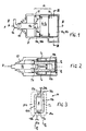
- the magnetic trigger shown on the figure 1 is intended to be mounted in a circuit-breaker, contactor-circuit-breaker or similar protective switch-type apparatus and it comprises a magnetic circuit M having a fixed part 10, hereinafter called a fixed magnetic circuit, and a mobile part 11 , hereinafter referred to as a moving pallet; a permanent magnet A is associated with the fixed magnetic circuit 10 to impart to it a permanent magnetic flux.
- the fixed magnetic circuit 10 comprises two plates 10a, 10b, parallel to each other, of generally flat shape with mean planes Pa, Pb extending in a direction X.
- the wafers are preferably identical.
- On the plates 10a, 10b of the fixed magnetic circuit are arranged two respective coils Ca, Cb. These coils are electrically connected in series in a trigger control circuit in order to provide, in case of overcurrent in this circuit, the ampere-turns necessary for the displacement of the pallet 11.
- the pallet 11 is movable in translation in the X direction and is coupled to an end 12a of an actuating part such as a pusher 12.
- the pusher is able to actuate a trigger mechanism of the circuit breaker.
- the link R between the end 12a of the pusher 12 and an associated central recess 11a of the pallet 11 is slightly swiveling, as indicated in FIG. figure 1 , to optimize the gap between the pallet and the fixed circuit.
- the pusher is biased by a spring 13, for example a compression spring, tending to separate the pallet of the pole ends 14a, 14b of the branches of the fixed magnetic circuit.
- the palette is applied on the fixed magnetic circuit by the permanent magnet A against the spring force. The occurrence of an overcurrent in the coils causes the pallet 11 to detach from the fixed magnetic circuit 10 and the pusher 12 to move due to the force of the spring 13.
- Each plate 10a, 10b has on its short sides, between its pole ends 14a, 14b and its ends 15a, 15b opposite the ends 14a, 14b, a recessed portion 16a, 16b which receives the coils Ca, Cb so as to reduce clutter of the trigger.
- the ends 15a, 15b of the plates 10a, 10b are intended to grip the permanent magnet A and to determine a magnetic flux deflection path T2.
- the ends 15a, 15b of the plates are shaped in a specific manner and comprise, to form two air gaps, on one side a respective lug 17a, 17b and on the other side a flange 18a, 18b defining the narrowed portion 16a, 16b .
- each lug 17a, 17b integral with a wafer defines with the opposite flange 18b, 18a of the other wafer a predetermined transverse air gap 20a, 20b.
- Transverse air gap means that the gap extends in a plane perpendicular to the X direction.
- the tabs 17a, 17b constitute flux deflecting branches of the magnetic circuit extending or continuing transversely (that is to say, perpendicular to the planes Pa, Pb and in the X direction) the main branches 19a, 19b formed by the plates 10a. , 10b, for channeling the induced magnetic flux in an overcurrent state.
- the pads thus have a shape L - or small wing and large wing - whose large wing is formed by the main branch and whose small wing is constituted by the leg or secondary branch.
- the permanent magnet A is inserted between the plates 10a, 10b at the level of the transverse tabs 17a, 17b and flanges 18a, 18b so as to brace the wafers arranged somehow head-to-tail (see figure 3 ); it is seen in this figure that, in cross section, the plates have at their ends 15a, 15b an L-shaped to embrace the magnet A by generating the two air gaps 20a, 20b. It is interesting to have identical pads, which simplifies the realization of the trigger.
- the coils Ca, Cb are wound half on an insulating half-shell 21a, 21b and half on the respective plate 10a, 10b, so as to be in direct contact with the latter on its inner face (see figure 2 ).
- the half-shells are U-shaped wrapping wafers 10a, 10b and provide abutments 22a, 22b for shoulders 23a, 23b provided at any suitable place of the wafers.
- the assembled half-shells constitute a shell or carcass for mounting the coils, this carcass being housed in an insulating body D of the release.
- the body D has an opening 24 for the pusher 12 and constitutes a support for the spring 13.
- the described trigger works as follows.
- the pallet 11 In the absence of overcurrent in the coils Ca, Cb, the pallet 11 is applied to the pole surfaces of the ends 14a, 14b of the magnetic plates 10a, 10b by the permanent magnet A against the force of the spring 13
- the flow developed by A circulates in a main loop T1 formed by the main branches 19a, 19b of the plates and the pallet 11.
- the coils develop a magnetic flux which opposes the flow of the permanent magnet and which deviates it to the secondary branches formed by the tabs 17a, 17b; the flux created by the permanent magnet then passes through a deflection loop T2 comprising the tabs 17a, 17b of the plates, the air gaps 20a, 20b and the flanges 18a, 18b of the plates.
Landscapes
- Physics & Mathematics (AREA)
- Electromagnetism (AREA)
- Breakers (AREA)
- Electromagnets (AREA)
- Driving Mechanisms And Operating Circuits Of Arc-Extinguishing High-Tension Switches (AREA)
Claims (7)
- Magnetauslöser für ein elektrisches Schaltgerät, der einen ortsfesten Magnetkreis (10), dem ein Dauermagnet (A) zugeordnet ist, mindestens eine Spule (Ca, Cb), die von einem elektrischen Strom durchflossen werden kann und einem Zweig (10a, 10b) des Kreises zugeordnet ist, um einen vom Strom abhängenden Magnetfluss zu bestimmen, sowie einen verschiebbaren Anker (11) aufweist, der mit einem Betätigungsbauteil (12) gekoppelt ist, das von einer Feder (13) beaufschlagt wird und mit dem ortsfesten Magnetkreis eine Hauptflussschleife (T1) bestimmt, wobei der Magnetkreis (10) in Höhe des Magnets (A) mindestens eine Magnetfluss-Umlenklasche (17a, 17b) aufweist, die eine Sekundärflussschleife (T2) definiert, die mit mindestens einem Sekundärluftspalt (20a, 20b) versehen ist,
wobei die Lasche bezüglich des ortsfesten Magnetkreises (10) und des Magnets (A) so angeordnet ist, dass ein Überstrom in der Spule den Fluss des Magnets zur Sekundärschleife (T2) umlenkt, wodurch die Bewegung des Betätigungsbauteils (12) ermöglicht wird,
dadurch gekennzeichnet, dass:- der Magnetkreis zwei parallele Plättchen (10a, 10b) aufweist, die je einen Hauptzweig (19a, 19b) und eine Umlenklasche (17a, 17b) aufweisen, wobei die freien Enden der Laschen zwei sekundäre Querluftspalte (20a, 20b) definieren, und dadurch, dass- der Magnet (A) zwischen den Plättchen in Höhe der Laschen angeordnet ist. - Auslöser nach Anspruch 1, dadurch gekennzeichnet, dass die Plättchen (10a, 10b) des Magnetkreises gleich sind, und dass die Lasche (17a, 17b) eines Plättchens quer zum Zweig (19a, 19b) ausgerichtet ist und sich bis zum anderen Plättchen erstreckt, indem sie von diesem durch den sekundären Luftspalt (20a, 20b) getrennt ist.
- Auslöser nach Anspruch 1, dadurch gekennzeichnet, dass jedem Plättchen (10a, 10b) eine Spule (Ca, Cb) zugeordnet ist.
- Auslöser nach Anspruch 1, dadurch gekennzeichnet, dass jedes Plättchen (10a, 10b) ein Polende (14a,b) und ein dem Magnet (A) benachbartes gegenüberliegendes Ende (15a,b) sowie kleine Seiten aufweist, die zwischen den Enden (14a,b; 15a,b) eine Vertiefung (16a, 16b) für den Durchgang der Wicklungen der jeweiligen Spule (Ca, Cb) aufweisen.
- Auslöser nach Anspruch 3, dadurch gekennzeichnet, dass jede Spule (Ca, Cb) auf eine isolierende Halbschale (21a, 21b) mit U-förmigem Querschnitt gewickelt ist, indem sie durch die Schenkel des U die kleinen Seiten des entsprechenden Plättchens umhüllt, so dass die Spule einer Seitenfläche des Plättchens direkt benachbart ist, wobei die Halbschalen so zusammengesetzt werden, dass sie eine isolierende Struktur bilden, die die Spulen trägt und die Plättchen enthält.
- Auslöser nach Anspruch 5, dadurch gekennzeichnet, dass die isolierende Struktur Anschläge (22a, 22b) zum Auflegen der Zweige des Magnetkreises definiert, wobei diese Anschläge eine gemeinsame Bezugsebene für den Anker bilden.
- Auslöser nach Anspruch 1, dadurch gekennzeichnet, dass der Anker (11) über eine drehende Verbindung (R) mit dem Betätigungsbauteil (12) verbunden ist, das translationsbeweglich ist und von der Feder (13) beaufschlagt wird.
Applications Claiming Priority (2)
| Application Number | Priority Date | Filing Date | Title |
|---|---|---|---|
| FR9916310 | 1999-12-20 | ||
| FR9916310A FR2802702B1 (fr) | 1999-12-20 | 1999-12-20 | Declencheur magnetique |
Publications (2)
| Publication Number | Publication Date |
|---|---|
| EP1111643A1 EP1111643A1 (de) | 2001-06-27 |
| EP1111643B1 true EP1111643B1 (de) | 2008-06-18 |
Family
ID=9553685
Family Applications (1)
| Application Number | Title | Priority Date | Filing Date |
|---|---|---|---|
| EP00403539A Expired - Lifetime EP1111643B1 (de) | 1999-12-20 | 2000-12-15 | Magnetauslöser |
Country Status (5)
| Country | Link |
|---|---|
| US (1) | US6472964B2 (de) |
| EP (1) | EP1111643B1 (de) |
| DE (1) | DE60039222D1 (de) |
| ES (1) | ES2304342T3 (de) |
| FR (1) | FR2802702B1 (de) |
Families Citing this family (1)
| Publication number | Priority date | Publication date | Assignee | Title |
|---|---|---|---|---|
| US10523180B2 (en) | 2016-03-11 | 2019-12-31 | Akoustis, Inc. | Method and structure for single crystal acoustic resonator devices using thermal recrystallization |
Citations (1)
| Publication number | Priority date | Publication date | Assignee | Title |
|---|---|---|---|---|
| DE8024489U1 (de) * | 1980-09-12 | 1980-12-11 | Siemens Ag, 1000 Berlin Und 8000 Muenchen | Auslöser, insbesondere Haltemagnetauslöser für Fehlerstromschutzschalter |
Family Cites Families (3)
| Publication number | Priority date | Publication date | Assignee | Title |
|---|---|---|---|---|
| DE1051370B (de) * | 1958-01-14 | 1959-02-26 | Siemens Ag | Fehlerstromschutzschalter |
| GB2109165B (en) * | 1981-05-01 | 1985-01-30 | Ledex Inc | Trip solenoid |
| DE19820768A1 (de) * | 1998-05-08 | 1999-11-11 | Siemens Ag | Haltemagnetauslöser |
-
1999
- 1999-12-20 FR FR9916310A patent/FR2802702B1/fr not_active Expired - Fee Related
-
2000
- 2000-12-15 DE DE60039222T patent/DE60039222D1/de not_active Expired - Lifetime
- 2000-12-15 ES ES00403539T patent/ES2304342T3/es not_active Expired - Lifetime
- 2000-12-15 EP EP00403539A patent/EP1111643B1/de not_active Expired - Lifetime
- 2000-12-20 US US09/739,784 patent/US6472964B2/en not_active Expired - Lifetime
Patent Citations (1)
| Publication number | Priority date | Publication date | Assignee | Title |
|---|---|---|---|---|
| DE8024489U1 (de) * | 1980-09-12 | 1980-12-11 | Siemens Ag, 1000 Berlin Und 8000 Muenchen | Auslöser, insbesondere Haltemagnetauslöser für Fehlerstromschutzschalter |
Also Published As
| Publication number | Publication date |
|---|---|
| FR2802702B1 (fr) | 2002-02-01 |
| DE60039222D1 (de) | 2008-07-31 |
| US20020050879A1 (en) | 2002-05-02 |
| FR2802702A1 (fr) | 2001-06-22 |
| EP1111643A1 (de) | 2001-06-27 |
| US6472964B2 (en) | 2002-10-29 |
| ES2304342T3 (es) | 2008-10-16 |
Similar Documents
| Publication | Publication Date | Title |
|---|---|---|
| EP0064906B1 (de) | Mehrpoliger Schutzschalter mit auswechselbarer magnetothermischer Auslöseeinheit | |
| EP0369899B1 (de) | Magnetischer Auslöser mit breitem Bereich zur Regelung des Auslöseansprechwertes | |
| EP0177380B1 (de) | Schaltvorrichtung mit veränderlicher Zusammensetzung mittels Zusammenbau von modularen Elementen | |
| EP0076719A1 (de) | Mehrpoliger Schutzschalter mit auswechselbarer Auslöseeinheit | |
| EP0589779B1 (de) | Leitungsschutzschalter mit magnetischer Blasschleife | |
| EP1111643B1 (de) | Magnetauslöser | |
| FR2753836A1 (fr) | Declencheur electromagnetique pour appareil electrique de protection | |
| EP0649158B1 (de) | Differentialschutzblock mit Kabeldurchgang | |
| EP0569652A1 (de) | Magnetauslöser für Schutzschalter, entsprechende Baugruppe und diese enthaltende Schutzschalter | |
| FR2792108A1 (fr) | Electroaimant a courant continu | |
| US2890306A (en) | Electromagnetic circuit breaker | |
| EP0004801B1 (de) | Schalter mit einer elektromagnetischen Einrichtung zur schnellen Öffnung des beweglichen Kontaktes | |
| EP0419325B1 (de) | Strombegrenzende Schaltvorrichtung | |
| WO2010109129A1 (fr) | Déclencheur magnétothermique | |
| EP0508846A1 (de) | Verbesserter enkelpoliger modularer Schalter und dessen Aufbau | |
| EP0996959B1 (de) | Elektrischer leistungsschalter für elektrische anlagen mit niederwechselspannung | |
| EP0295162B1 (de) | Magnetothermische Auslöseeinheit für Lastschalter oder Differentiallastschalter | |
| FR2828329A1 (fr) | Dispositif pour l'extinction d'un arc electrique | |
| EP0905735B1 (de) | Schutzschalter mit elektromagnetischen Auslöser mit Antrieb für einen beweglichen und gabelförmigen Kontakt | |
| JPH0345844B2 (de) | ||
| EP0045672B1 (de) | Kleinschalter mit Abschaltung des Nulleiters und des Phasenleiters | |
| FR3151425A1 (fr) | Déclencheur électromagnétique du type relais polarisé à haute sensibilité et appareillage électrique différentiel associé | |
| JP3173635B2 (ja) | 漏電遮断器の漏電引外し装置 | |
| FR2676860A1 (fr) | Declencheur electromagnetique pour un disjoncteur electrique a bas calibres. | |
| US5192934A (en) | Circuit breaker having a trip actuator |
Legal Events
| Date | Code | Title | Description |
|---|---|---|---|
| PUAI | Public reference made under article 153(3) epc to a published international application that has entered the european phase |
Free format text: ORIGINAL CODE: 0009012 |
|
| AK | Designated contracting states |
Kind code of ref document: A1 Designated state(s): DE ES GB IT |
|
| AX | Request for extension of the european patent |
Free format text: AL;LT;LV;MK;RO;SI |
|
| 17P | Request for examination filed |
Effective date: 20010716 |
|
| AKX | Designation fees paid |
Free format text: DE ES GB IT |
|
| RAP1 | Party data changed (applicant data changed or rights of an application transferred) |
Owner name: SCHNEIDER ELECTRONIC INDUSTRIES SAS |
|
| RAP1 | Party data changed (applicant data changed or rights of an application transferred) |
Owner name: SCHNEIDER ELECTRIC INDUSTRIES SAS |
|
| 17Q | First examination report despatched |
Effective date: 20051215 |
|
| GRAP | Despatch of communication of intention to grant a patent |
Free format text: ORIGINAL CODE: EPIDOSNIGR1 |
|
| GRAS | Grant fee paid |
Free format text: ORIGINAL CODE: EPIDOSNIGR3 |
|
| GRAA | (expected) grant |
Free format text: ORIGINAL CODE: 0009210 |
|
| AK | Designated contracting states |
Kind code of ref document: B1 Designated state(s): DE ES GB IT |
|
| REG | Reference to a national code |
Ref country code: GB Ref legal event code: FG4D Free format text: NOT ENGLISH |
|
| REF | Corresponds to: |
Ref document number: 60039222 Country of ref document: DE Date of ref document: 20080731 Kind code of ref document: P |
|
| REG | Reference to a national code |
Ref country code: ES Ref legal event code: FG2A Ref document number: 2304342 Country of ref document: ES Kind code of ref document: T3 |
|
| PLBE | No opposition filed within time limit |
Free format text: ORIGINAL CODE: 0009261 |
|
| STAA | Information on the status of an ep patent application or granted ep patent |
Free format text: STATUS: NO OPPOSITION FILED WITHIN TIME LIMIT |
|
| 26N | No opposition filed |
Effective date: 20090319 |
|
| REG | Reference to a national code |
Ref country code: DE Ref legal event code: R084 Ref document number: 60039222 Country of ref document: DE |
|
| PGFP | Annual fee paid to national office [announced via postgrant information from national office to epo] |
Ref country code: IT Payment date: 20171213 Year of fee payment: 18 Ref country code: GB Payment date: 20171219 Year of fee payment: 18 |
|
| PGFP | Annual fee paid to national office [announced via postgrant information from national office to epo] |
Ref country code: ES Payment date: 20180129 Year of fee payment: 18 |
|
| GBPC | Gb: european patent ceased through non-payment of renewal fee |
Effective date: 20181215 |
|
| PG25 | Lapsed in a contracting state [announced via postgrant information from national office to epo] |
Ref country code: IT Free format text: LAPSE BECAUSE OF NON-PAYMENT OF DUE FEES Effective date: 20181215 |
|
| PG25 | Lapsed in a contracting state [announced via postgrant information from national office to epo] |
Ref country code: GB Free format text: LAPSE BECAUSE OF NON-PAYMENT OF DUE FEES Effective date: 20181215 |
|
| PGFP | Annual fee paid to national office [announced via postgrant information from national office to epo] |
Ref country code: DE Payment date: 20191028 Year of fee payment: 20 |
|
| REG | Reference to a national code |
Ref country code: ES Ref legal event code: FD2A Effective date: 20200203 |
|
| PG25 | Lapsed in a contracting state [announced via postgrant information from national office to epo] |
Ref country code: ES Free format text: LAPSE BECAUSE OF NON-PAYMENT OF DUE FEES Effective date: 20181216 |
|
| REG | Reference to a national code |
Ref country code: DE Ref legal event code: R071 Ref document number: 60039222 Country of ref document: DE |