EP0337893B1 - Kassettendichtung - Google Patents
Kassettendichtung Download PDFInfo
- Publication number
- EP0337893B1 EP0337893B1 EP89401042A EP89401042A EP0337893B1 EP 0337893 B1 EP0337893 B1 EP 0337893B1 EP 89401042 A EP89401042 A EP 89401042A EP 89401042 A EP89401042 A EP 89401042A EP 0337893 B1 EP0337893 B1 EP 0337893B1
- Authority
- EP
- European Patent Office
- Prior art keywords
- seal
- lips
- bearing surface
- packing
- ring
- Prior art date
- Legal status (The legal status is an assumption and is not a legal conclusion. Google has not performed a legal analysis and makes no representation as to the accuracy of the status listed.)
- Expired - Lifetime
Links
Images
Classifications
-
- F—MECHANICAL ENGINEERING; LIGHTING; HEATING; WEAPONS; BLASTING
- F16—ENGINEERING ELEMENTS AND UNITS; GENERAL MEASURES FOR PRODUCING AND MAINTAINING EFFECTIVE FUNCTIONING OF MACHINES OR INSTALLATIONS; THERMAL INSULATION IN GENERAL
- F16D—COUPLINGS FOR TRANSMITTING ROTATION; CLUTCHES; BRAKES
- F16D3/00—Yielding couplings, i.e. with means permitting movement between the connected parts during the drive
- F16D3/84—Shrouds, e.g. casings, covers; Sealing means specially adapted therefor
-
- F—MECHANICAL ENGINEERING; LIGHTING; HEATING; WEAPONS; BLASTING
- F16—ENGINEERING ELEMENTS AND UNITS; GENERAL MEASURES FOR PRODUCING AND MAINTAINING EFFECTIVE FUNCTIONING OF MACHINES OR INSTALLATIONS; THERMAL INSULATION IN GENERAL
- F16J—PISTONS; CYLINDERS; SEALINGS
- F16J15/00—Sealings
- F16J15/16—Sealings between relatively-moving surfaces
- F16J15/32—Sealings between relatively-moving surfaces with elastic sealings, e.g. O-rings
- F16J15/3248—Sealings between relatively-moving surfaces with elastic sealings, e.g. O-rings provided with casings or supports
- F16J15/3252—Sealings between relatively-moving surfaces with elastic sealings, e.g. O-rings provided with casings or supports with rigid casings or supports
- F16J15/3256—Sealings between relatively-moving surfaces with elastic sealings, e.g. O-rings provided with casings or supports with rigid casings or supports comprising two casing or support elements, one attached to each surface, e.g. cartridge or cassette seals
Definitions
- the present invention relates to a cartridge seal intended to be mounted between a shaft and a cylindrical surface, in particular between an axle and a wheel hub of a vehicle, in particular an industrial vehicle.
- seals comprising a first inner seal vis-à-vis the lubrication fluid, comprising at least one sealing lip oriented radially inwardly bearing against an inner axial cylindrical bearing of the seal, and a second outer seal, comprising two or more lips, with respect to external contaminants oriented radially outward bearing against an external axial cylindrical bearing surface of the joint.
- first inner seal vis-à-vis the lubrication fluid comprising at least one sealing lip oriented radially inwardly bearing against an inner axial cylindrical bearing of the seal
- second outer seal comprising two or more lips
- the present invention proposes to produce a seal avoiding the drawbacks of previously known seals, in particular in the case of overpressures, and ensuring perfect and reliable sealing in operation vis-à-vis the surrounding media, that is to say -display when used between an axle and a wheel hub, vis-à-vis the lubrication fluid on the one hand, and vis-à-vis external contaminants such as mud, water and dust coming in particular from brake linings on the other hand.
- the lips of the outer seal inclined, preferably at an angle between about 20 ° and about 50 ° relative to the axis of the seal, towards the front face of the seal.
- the interior seal advantageously comprises, in addition to the sealing lip or lips bearing against the inner axial cylindrical bearing surface of the inner ring, at least one additional lip oriented radially outwardly bearing against the frontal radial bearing of the inner ring.
- the orientation of the lips of the outer seal, and if necessary of the additional lip of the inner seal means that in the event of overpressure, air can escape freely during operation through the external annular channel of the seal.
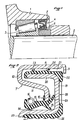
- FIG. 1 illustrates the mounting of the hub 1 of a vehicle wheel on an axle 2 by means of a bearing 3 with the use of a seal according to the invention generally designated by 4 and mounted between a bearing cylindrical 5 of the hub and a ring 6 integral with the axle 2.
- the seal has a metal outer ring 7 having an axial cylindrical outer surface 8 provided with one end curved 9 for its crimping to the inner ring, and connecting at its other end by a substantially radial bearing 10 to an inclined bearing 11 terminated by a radial bearing 12 on which is adhered a seal 13, for example NBR, comprising a main sealing lip 14 and a secondary lip 15.
- a garter spring 16 applies the lip 14 against an internal axial cylindrical bearing surface 17 of the internal metal ring of the seal, generally designated by 18, of section substantially in the shape of a U, comprising, in one piece with the bearing 17, a radial bearing 19 and an outer axial cylindrical bearing 20.
- An annular channel 21 is formed between the bearing 20 of the inner ring and the bearing 8 facing the outer ring.
- This channel 21 opens onto the front face of the seal (on the right in the drawing), that is to say opposite to the face of the seal facing the fluid vis-à-vis which the seal must be made, in particular the lubricating oil of the bearing 3 illustrated in FIG. 1.
- an external sealing gasket 22 in particular made of NBR, is adhered, making a seal against external contaminants, and comprising in the illustrated example two lips 23, 24 oriented radially towards outside and towards the front face of the joint. These lips make with the axis of the joint an angle of the order of 45 ° and are in abutment against the bearing surface 8 of the outer ring.
- the inner seal 13 comprises, in the example illustrated, an additional lip 25 oriented radially outwards and in the direction of the front face of the seal, bearing against the front radial surface 19 of the inner ring, this lip 25 making an angle with the joint axis of the order of 45 °.
- the inner axial cylindrical bearing surface 17 of the inner ring comprises a ribbed seal 26, in particular made of rubber intended to come into contact with the ring 6, and a curved end portion 27 allowing easy mounting of the lips of sealing 14 and 15 on the bearing 17.
- the fitting force of the outer ring 7 in the hub is greater than the fitting force of the inner ring 18 on the ring 6 secured to the axle. This characteristic ensures that when the hub of the wheel is dismantled the outer ring 7 remains in place on the latter and the inner ring 18 is driven as a result of the crimping at 9 simultaneously driving the ring 6 and the bearing.
- the complete gasket comprising the inner and outer rings is put in place, with the press, after the bearing 3, the inner ring 18 being forced onto the ring 6 by means of the bearing 3.
- the outer lips 23, 24 oriented in the mounting direction avoid any overpressure during this mounting and cannot turn over. In addition, they maintain the front position before the end 9 is bent, an attempt to separate the two rings creating a sufficient vacuum to prevent disassembly.
Landscapes
- Engineering & Computer Science (AREA)
- General Engineering & Computer Science (AREA)
- Mechanical Engineering (AREA)
- Sealing With Elastic Sealing Lips (AREA)
- Sealing Of Bearings (AREA)
- Rolling Contact Bearings (AREA)
Claims (3)
- Dichtungskartusche zum Einbau zwischen einer Welle und einer Zylinderfläche, insbesondere zwischen Achse und Nabe eines Fahrzeugrades, umfassend einen Innenring (18) und einen Außenring (7), die relativ zueinander drehbar sind, eine erste, innere Dichtanordnung (13) mit mindestens einer radial nach innen weisenden, an einem inneren axialen Zylinderabschnitt (17) der Dichtung anliegenden Dichtlippe (14, 15), und eine zweite, äußere Dichtanordnug (22) mit mindestens zwei in Richtung der Stirnfläche der Dichtung radial nach außen weisenden, an einem äußeren axialen Zylinderabschnitt (8) der Richtung anliegenden Dichtlippen (23, 24), dadurch gekennzeichnet, daß der Innenring (18) im wesentlichen U-förmigen Querschnitt hat, dessen Steg einen radialen stirnseitigen Abschnitt (19) der Dichtung und dessen Schenkel einen äußeren axialen Zylinderabschnitt (20), an dem die äußere Dichtanordnung (22) angeordnet ist, bzw. einen inneren axialen Zylinderabschnitt (17) bilden, an dem die Lippe bzw. Lippen (14, 15) der inneren Dichtanordnung (13) anliegen, wobei die Lippen (23, 24) der äußeren Dichtanordnung (22) in einem zwischen den äußeren axialen Zylinderabschnitten (8, 20) des Außenrings (7) und des Innenrings (18) vorhandenen Ringraum (21) liegen.
- Dichtung nach Anspruch 1, dadurch gekennzeichnet, daß die Lippen (23, 24) der äußeren Dichtanordnung (22) unter einem Winkel zwischen etwa 20° und etwa 50° zur Achse der Dichtung geneigt sind.
- Dichtung nach Anspruch 1 oder 2, dadurch gekennzeichnet, daß die innere Dichtanordnung (13) mindestens eine zusätzliche, radial nach außen weisende und an dem radialen stirnseitigen Abschnitt (19) des Innenrings (18) anliegende Lippe (25) aufweist.
Applications Claiming Priority (2)
| Application Number | Priority Date | Filing Date | Title |
|---|---|---|---|
| FR8804949 | 1988-04-14 | ||
| FR8804949A FR2630179B1 (fr) | 1988-04-14 | 1988-04-14 | Joint d'etancheite en cartouche |
Publications (2)
| Publication Number | Publication Date |
|---|---|
| EP0337893A1 EP0337893A1 (de) | 1989-10-18 |
| EP0337893B1 true EP0337893B1 (de) | 1992-12-16 |
Family
ID=9365313
Family Applications (1)
| Application Number | Title | Priority Date | Filing Date |
|---|---|---|---|
| EP89401042A Expired - Lifetime EP0337893B1 (de) | 1988-04-14 | 1989-04-14 | Kassettendichtung |
Country Status (5)
| Country | Link |
|---|---|
| EP (1) | EP0337893B1 (de) |
| JP (1) | JPH01303377A (de) |
| KR (1) | KR890015921A (de) |
| DE (1) | DE68903866T2 (de) |
| FR (1) | FR2630179B1 (de) |
Families Citing this family (20)
| Publication number | Priority date | Publication date | Assignee | Title |
|---|---|---|---|---|
| JPH0745745B2 (ja) * | 1989-03-23 | 1995-05-17 | 油谷重工株式会社 | 旋回減速機 |
| JPH0747650Y2 (ja) * | 1989-03-30 | 1995-11-01 | 内山工業株式会社 | 組合せシール |
| DE3940003A1 (de) * | 1989-12-02 | 1991-06-06 | Freudenberg Carl Fa | Kassettendichtung |
| JPH0432361U (de) * | 1990-07-13 | 1992-03-16 | ||
| DE4123688A1 (de) * | 1991-07-17 | 1993-01-21 | Goetze Ag | Wellendichtring |
| US5813675A (en) * | 1995-10-31 | 1998-09-29 | The Timken Company | Multibarrier seal |
| US20020011710A1 (en) | 1997-09-25 | 2002-01-31 | Oldenburg Michael R. | Retrofittable severe duty seal for a shaft |
| US6186507B1 (en) | 1997-09-25 | 2001-02-13 | Michael R. Oldenburg | Retrofittable severe duty seal for a shaft |
| US6692007B2 (en) | 2001-10-31 | 2004-02-17 | Transcom, Inc. | Seal for a shaft |
| KR100468367B1 (ko) * | 2002-08-19 | 2005-01-27 | 에프에이지베어링코리아유한회사 | 워터펌프 베어링의 시일링장치 |
| US6726210B2 (en) * | 2002-09-25 | 2004-04-27 | Li Ming Machinery Industrial Co., Ltd. | Sealing device for a gear box |
| WO2006085651A1 (ja) * | 2005-02-14 | 2006-08-17 | Nsk Ltd. | ハブユニット軸受 |
| JP5479771B2 (ja) * | 2009-04-28 | 2014-04-23 | 光洋シーリングテクノ株式会社 | 密封装置 |
| JP5312243B2 (ja) * | 2009-07-23 | 2013-10-09 | Ntn株式会社 | カムフォロア及びカムフォロアの製造方法 |
| US9951855B2 (en) | 2009-07-17 | 2018-04-24 | Ntn Corporation | Cam follower and method for producing cam follower |
| JP2011021715A (ja) * | 2009-07-17 | 2011-02-03 | Ntn Corp | カムフォロア |
| CN102011746B (zh) * | 2010-11-11 | 2012-07-04 | 华东理工大学 | 汽车水泵轴承密封装置 |
| IT201600070543A1 (it) * | 2016-07-06 | 2018-01-06 | Rolf S P A | Complesso di tenuta a cassetta, in particolare per assali di veicoli |
| JP7478516B2 (ja) * | 2018-04-06 | 2024-05-07 | ナブテスコ株式会社 | シール機構及び当該シール機構を備えた装置 |
| KR20190117391A (ko) * | 2018-04-06 | 2019-10-16 | 나부테스코 가부시키가이샤 | 시일 기구 및 당해 시일 기구를 구비한 장치 |
Family Cites Families (3)
| Publication number | Priority date | Publication date | Assignee | Title |
|---|---|---|---|---|
| GB881607A (en) * | 1959-09-14 | 1961-11-08 | Federal Mogul Bower Bearings | Fluid sealing means between two relatively rotating members |
| FR2527297A1 (fr) * | 1982-05-18 | 1983-11-25 | Procal | Joint d'etancheite en cartouche |
| DE8612910U1 (de) * | 1986-05-12 | 1987-06-25 | Goetze Ag, 5093 Burscheid, De |
-
1988
- 1988-04-14 FR FR8804949A patent/FR2630179B1/fr not_active Expired - Lifetime
-
1989
- 1989-04-14 EP EP89401042A patent/EP0337893B1/de not_active Expired - Lifetime
- 1989-04-14 JP JP1096216A patent/JPH01303377A/ja active Pending
- 1989-04-14 KR KR1019890005068A patent/KR890015921A/ko not_active Application Discontinuation
- 1989-04-14 DE DE8989401042T patent/DE68903866T2/de not_active Expired - Lifetime
Also Published As
| Publication number | Publication date |
|---|---|
| KR890015921A (ko) | 1989-11-27 |
| JPH01303377A (ja) | 1989-12-07 |
| FR2630179B1 (fr) | 1991-03-29 |
| DE68903866D1 (de) | 1993-01-28 |
| DE68903866T2 (de) | 1993-06-03 |
| FR2630179A1 (fr) | 1989-10-20 |
| EP0337893A1 (de) | 1989-10-18 |
Similar Documents
| Publication | Publication Date | Title |
|---|---|---|
| EP0337893B1 (de) | Kassettendichtung | |
| US5201529A (en) | Sealing device | |
| FR2543643A1 (fr) | Dispositif d'etancheite a l'huile | |
| EP0631072B1 (de) | Dichtung für Drehwelle | |
| EP0173607B2 (de) | Nadellager, insbesondere Hülsenadellager mit verstärkter Dichtung | |
| FR2517392A1 (fr) | Etancheite pour paliers a roulement | |
| FR2484043A1 (fr) | Dispositif d'etancheite pour arbre tournant et ensemble comportant un tel dispositif | |
| FR2504231A3 (fr) | Joint d'etancheite comprenant deux levres dont l'une est axiale et l'autre radiale, ainsi qu'un labyrinthe | |
| EP1210525B1 (de) | Selbsteinstellendes kupplungsausrücklager mit einer elastischen hülse | |
| FR2544442A1 (fr) | Joint a fluide, notamment a lubrifiant | |
| EP0538130B1 (de) | Führungshülse mit integrierter Dichtung für das Kupplungsausrücklager von Kraftfahrzeuggetrieben | |
| EP0007832A1 (de) | Dichtung für koaxial drehende Teile | |
| FR2527297A1 (fr) | Joint d'etancheite en cartouche | |
| FR2559231A1 (fr) | Bague d'etancheite radiale pour arbre | |
| EP0464379B1 (de) | Dichtung, insbesondere für ein Walzlager | |
| FR2482878A1 (de) | ||
| EP0571284B1 (de) | Kurbelwellendichtung für eine Verbrennungskraftmaschine, besonders für Fahrzeug | |
| EP0192615B1 (de) | Radiale Stahlabdichtungsvorrichtung für Wälzlager | |
| FR2666394A1 (fr) | Ensemble d'etancheite. | |
| FR2640707A1 (fr) | Roulement, notamment du type a deux rangees de billes a contact oblique, immobilise dans un alesage-logement par un adaptateur | |
| FR2459927A1 (fr) | Joint d'etancheite a glissement frontal | |
| FR2652623A1 (fr) | Dispositif de butee d'embrayage a autocentrage du type tiree. | |
| FR2745618A1 (fr) | Dispositif de debrayage pour embrayage de vehicule automobile comportant un joint d'arbre tournant perfectionne | |
| FR3039602A1 (fr) | Assemblage de roulement | |
| FR2646888A1 (fr) | Dispositif d'etanchement pour arbre tournant, notamment pour arbre tournant a grande vitesse |
Legal Events
| Date | Code | Title | Description |
|---|---|---|---|
| PUAI | Public reference made under article 153(3) epc to a published international application that has entered the european phase |
Free format text: ORIGINAL CODE: 0009012 |
|
| AK | Designated contracting states |
Kind code of ref document: A1 Designated state(s): DE GB IT |
|
| 17P | Request for examination filed |
Effective date: 19891219 |
|
| 17Q | First examination report despatched |
Effective date: 19910627 |
|
| GRAA | (expected) grant |
Free format text: ORIGINAL CODE: 0009210 |
|
| AK | Designated contracting states |
Kind code of ref document: B1 Designated state(s): DE GB IT |
|
| REF | Corresponds to: |
Ref document number: 68903866 Country of ref document: DE Date of ref document: 19930128 |
|
| ITF | It: translation for a ep patent filed |
Owner name: MODIANO & ASSOCIATI S.R.L. |
|
| GBT | Gb: translation of ep patent filed (gb section 77(6)(a)/1977) |
Effective date: 19930115 |
|
| PLBE | No opposition filed within time limit |
Free format text: ORIGINAL CODE: 0009261 |
|
| STAA | Information on the status of an ep patent application or granted ep patent |
Free format text: STATUS: NO OPPOSITION FILED WITHIN TIME LIMIT |
|
| 26N | No opposition filed | ||
| REG | Reference to a national code |
Ref country code: GB Ref legal event code: IF02 |
|
| PGFP | Annual fee paid to national office [announced via postgrant information from national office to epo] |
Ref country code: DE Payment date: 20080423 Year of fee payment: 20 |
|
| PGFP | Annual fee paid to national office [announced via postgrant information from national office to epo] |
Ref country code: IT Payment date: 20080422 Year of fee payment: 20 |
|
| PGFP | Annual fee paid to national office [announced via postgrant information from national office to epo] |
Ref country code: GB Payment date: 20080422 Year of fee payment: 20 |
|
| REG | Reference to a national code |
Ref country code: GB Ref legal event code: PE20 Expiry date: 20090413 |
|
| PG25 | Lapsed in a contracting state [announced via postgrant information from national office to epo] |
Ref country code: GB Free format text: LAPSE BECAUSE OF EXPIRATION OF PROTECTION Effective date: 20090413 |