EP0336729A2 - Automatische Melkvorrichtungen - Google Patents
Automatische Melkvorrichtungen Download PDFInfo
- Publication number
- EP0336729A2 EP0336729A2 EP89303346A EP89303346A EP0336729A2 EP 0336729 A2 EP0336729 A2 EP 0336729A2 EP 89303346 A EP89303346 A EP 89303346A EP 89303346 A EP89303346 A EP 89303346A EP 0336729 A2 EP0336729 A2 EP 0336729A2
- Authority
- EP
- European Patent Office
- Prior art keywords
- pulses
- pulse
- pulsation controller
- controller
- duration
- Prior art date
- Legal status (The legal status is an assumption and is not a legal conclusion. Google has not performed a legal analysis and makes no representation as to the accuracy of the status listed.)
- Withdrawn
Links
Images

Classifications
-
- A—HUMAN NECESSITIES
- A01—AGRICULTURE; FORESTRY; ANIMAL HUSBANDRY; HUNTING; TRAPPING; FISHING
- A01J—MANUFACTURE OF DAIRY PRODUCTS
- A01J5/00—Milking machines or devices
- A01J5/007—Monitoring milking processes; Control or regulation of milking machines
-
- A—HUMAN NECESSITIES
- A01—AGRICULTURE; FORESTRY; ANIMAL HUSBANDRY; HUNTING; TRAPPING; FISHING
- A01J—MANUFACTURE OF DAIRY PRODUCTS
- A01J5/00—Milking machines or devices
- A01J5/007—Monitoring milking processes; Control or regulation of milking machines
- A01J5/0075—Monitoring milking processes; Control or regulation of milking machines with a specially adapted stimulation of the teats
Definitions
- This invention relates to automatic milking apparatus and provides a pulsation controller for controlling the alternate vacuum and atmosphere pressure pulses to a milking machine clawpiece, both in the rate of such pulses in unit time and in the ratio of duration of the vacuum and the atmosphere pressure pulses, while preserving a preferred duration of the atmosphere pressure pulses.
- the pulse cycle rate is therefore varied solely by varying the duration of the ON pulses, while maintaining constant the duration of the OFF pulses at a preferred duration.
- Fig 1 shows a milking installation having, for clarity in the drawing, a cluster of four teat cups 1, 2, 3 and 4, which are pulse fed in unison from a single flexible pulse tube 5, by way of a claw-piece distributor 6.
- a pulsator 7 is electrically controlled by a pulsation controller 8 to connect the pulse tube 5 alternately to the atmosphere at a port 9 and to vacuum at one-half atmosphere pressure in a vacuum line 10 by way of a second port 11. Electrical pulses to the pulsator 7 are supplied from the pulsation controller 8 by way of a pair of conductors 12 and 13.
- the pulsation controller provides electrical pulses of twelve volts nominal amplitude, spaced apart by intervals of zero volts, to the pulsator 7. This nominal twelve volts amplitude has been found to be a practical voltage to be obtainable, at the required amperage, from readily available lead-acid batteries as the power source, or as a standby power source.
- the twelve volts pulses are referred to as ON pulses, corresponding to the supply of vacuum pulses, and the zero volt intervals are referred to as OFF pulses, corresponding to the supply of atmosphere pressure pulses.
- the pressure supplied to the pulse tube 5 is also supplied, by way of the claw-piece distributor 6, to the four flexible tubes 27 of the teat cup cluster 1-4, fitted around the four teats of a cow being milked.
- a continuous vacuum pressure of one-half atmosphere is applied to the four short milk tubes, 25.
- the core space 22 and the teat within are subject to a uniform vacuum pressure
- the annular space 23 is subject alternately to vacuum pressure and to atmosphere pressure.
- the teat cup liner 21 is held open and milk flow takes place.
- atmosphere pressure in the space 23 the liner 21 collapses onto the cow's teat, by reason of the pressure difference in the core space 22 and annular space 23, and milk flow ceases.
- the alternate opening and collapse of the liner 21 upon the cow's teat provides the necessary massage to the teat to maintain blood circulation.
- the liner collapsed, no milk-flow, phase duration is found to be critical to avoid incidence of udder infection.
- the present invention provides for pre-set adjustment of the no milk-flow interval the combined intervals C + D, between the values of .30 to 0.35 second and for the maintenance of that interval with variation of pulse cycle rate.
- the pulsation controller in the milking apparatus of the invention operates according to the following equation: where A, B, C and D are the intervals defined above, R is the pulse rate in cycles per minute and (C + D) is the constant, no milk-flow interval, as also defined above.
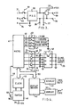
- Fig 4 shows, in part schematic form, the preferred example of pulsation controller, which is an electronic controller built around a number of standard I.C.s.
- the central unit of these is a microcomputer 41, which is a type Z8.6E21 from SGS-Thomson.
- This Z8 derivative includes internal ROM for programme storage, RAM for working memory, input and output ports, counter/timers and a clock pulse oscillator. It can also address external RAM and to this end is associated with a real time clock unit 45, described later.
- a power driver unit 48 comprises four power transistors of which one is referred 51.
- the + 14V terminal 35, Fig 3, is connected to terminal 35, Fig 4, and by a line 52 to all four power transistors 51.
- the output lines from transistors 51, one line referred 53, are connected to an output control pulse panel 49 carrying four output pulse terminal pairs, one pair of which are referred 54.
- Each transistor 51 is connected to a corresponding terminal pair.
- a signal LED 56 between each line 53 and earth indicates when the respective line is ON.
- microcomputer 41 The function of microcomputer 41 is to gate the four transistors 51 in sequence in order to provide output pulses in quadrature at the terminals 54, the pulse rate and OFF pulse duration being controlled by data entered from a four-button keypad 47.
- the keypad 47 has four push-buttons connected respectively by four lines, one referred 60, to four input port pins of microcomputer 41.
- the four push-buttons are respectively referenced 61, 62, 63 and 64.
- Push-buttons 61 and 62 serve a dual function, both to control the pulse rate at terminals 54 and to reset the real time clock 45.
- Pulse Rate button 64 is depressed. Button 61 then increments the pulse rate for so long as it is depressed. Button 62 decrements the pulse rate in similar manner.
- Time of Day button 63 is depressed. Button 61 then increments the “Minutes” setting. Button 62 increments the "Hours” setting.
- the OFF pulse duration is also set from the keypad 47.
- the OFF time being critical and, in order to avoid accidental or unauthorised alteration, a more complicated resetting procedure is required.
- Both Pulse Rate button 64 and Time of Day button 63 must be depressed together for 10 seconds . Button 61 then increments the OFF pulse duration and button 62 decrements this value.
- Limits are set, within the microcomputer 41 programme, for pulse rate and for OFF pulse duration values. Although either of buttons 61 and 62 continuously updates the relevant value for so long as the button remains depressed, the programme checks the resultant value. When a limit value is reached, further updating is inhibited.
- All intervals required by the microcomputer 41 programme, the pulse duration intervals in particular, are set using registers available in the microcomputer 41 chip.
- An interval timer makes use of 1 millisecond interrupts.
- the relevant interval register is loaded with the number of the 1 m sec intervals required by the particular interval.
- the register is then decremented to zero by successive interrupts to give the interval required.
- a data bus 50 interconnects the microcomputer 41, clock 45 and a display driver 42.
- the display driver 42 controls a four-digit LED display 43 and a three-digit LED display 43.
- Display 43 is a 4-digit 7-segment display which optionally shows Time of Day and Pulse Rate values.
- Display 44 is a 3-digit 7-segment display which shows the OFF pulse duration in milliseconds.
- the real time clock unit 45 is an Hitachi type HD 146818 X clock which includes a crystal clock oscillator and user RAM and is designed to operate on nominal 5V d.c. but down to 2.7V standby voltage.
- Terminal 39, Fig 3, carrying the +5V d.c. output is connected to terminal 39, Fig 4.
- a switch 46 monitors the supply voltage of +5V. When this supply voltage is present, a NiCd standby battery 65 is float-charged. If the + 5V supply fails, due to mains supply interruption to power supply unit 30, Fig 3, the battery 65 is switched into circuit to power the clock unit 45.
- the value settings set by the four buttons of keypad 47 are stored in the user RAM by the clock unit 45, so that these settings are not lost when mains power is lost.
- the switch 46 provides a master reset signal on line 66 to the microcomputer 41, which disables the control by the microcomputer 41 of the clock 45. This prevents the data stored in the clock 45 user RAM from being altered during power-down or power-up of the pulsation controller.
- a hexadecimal switch is connected to four input data pins of the microcomputer 41. This switch provides for the setting of up to sixteen values for default value of OFF pulse duration. The chosen setting is selected if the standby battery 65 fails. In normal operation, the switch setting is disabled.
- the programme checks the status of clock 45. If the data stored in the clock 45 user RAM is invalid, due to standby battery 65 failure as stated, the default OFF pulse duration is selected. A default rate value is also stored, so that both pulse rate and OFF duration revert to default settings.
- the microcomputer 41 programme writes the current values of pulse rate and OFF duration, whether normal operation values or default values, to the display driver 42 and hence to the relevant display 43 or 44.
- the programme periodically reads the Time of Day value of clock 45 and updates display 43 accordingly. In consequence, it is possible to select different stored settings of pulse rate and OFF duration for a.m. and for p.m. working:
- the four-phase quadrature pulse outputs at terminals 54 enables one, two or four pulsators, such as pulsator 7, Fig 1, to be controlled, whereby a teat cup cluster may be vacuum pulsed in unison, or with teat cup pairs alternately, or with the four teat cups in sequence, respectively.
Landscapes
- Life Sciences & Earth Sciences (AREA)
- Animal Husbandry (AREA)
- Environmental Sciences (AREA)
- External Artificial Organs (AREA)
- Electrotherapy Devices (AREA)
Applications Claiming Priority (2)
| Application Number | Priority Date | Filing Date | Title |
|---|---|---|---|
| GB888807999A GB8807999D0 (en) | 1988-04-06 | 1988-04-06 | Improvements in/relating to automatic milking apparatus |
| GB8807999 | 1988-04-06 |
Publications (2)
| Publication Number | Publication Date |
|---|---|
| EP0336729A2 true EP0336729A2 (de) | 1989-10-11 |
| EP0336729A3 EP0336729A3 (de) | 1990-10-03 |
Family
ID=10634631
Family Applications (1)
| Application Number | Title | Priority Date | Filing Date |
|---|---|---|---|
| EP19890303346 Withdrawn EP0336729A3 (de) | 1988-04-06 | 1989-04-05 | Automatische Melkvorrichtungen |
Country Status (3)
| Country | Link |
|---|---|
| EP (1) | EP0336729A3 (de) |
| GB (2) | GB8807999D0 (de) |
| NZ (1) | NZ228613A (de) |
Cited By (1)
| Publication number | Priority date | Publication date | Assignee | Title |
|---|---|---|---|---|
| NL9401937A (nl) * | 1994-04-27 | 1995-12-01 | Maasland Nv | Werkwijze voor het automatisch melken van dieren en inrichting waarin deze werkwijze kan worden toegepast. |
Family Cites Families (5)
| Publication number | Priority date | Publication date | Assignee | Title |
|---|---|---|---|---|
| US3703645A (en) * | 1971-01-18 | 1972-11-21 | William C Swift | Electronic timing system for milking |
| US4041904A (en) * | 1976-05-14 | 1977-08-16 | The De Laval Separator Company | Pneumatic pulsator for teat cups |
| DE2844562C2 (de) * | 1978-10-12 | 1983-01-05 | Bio-Melktechnik Swiss Hoefelmayr & Co, 9052 Niederteufen, Aargau | Verfahren zum selbsttätigen Ausmelken beim maschinellen Milchentzug |
| CH646254A5 (en) * | 1979-06-29 | 1984-11-15 | Applied Electronics Bv | Electronic pulsator tester |
| DE3609275A1 (de) * | 1986-03-19 | 1987-09-24 | Werner Ludwig Schmidt | Verfahren zum maschinellen milchentzug |
-
1988
- 1988-04-06 GB GB888807999A patent/GB8807999D0/en active Pending
-
1989
- 1989-04-05 NZ NZ22861389A patent/NZ228613A/en unknown
- 1989-04-05 EP EP19890303346 patent/EP0336729A3/de not_active Withdrawn
- 1989-04-05 GB GB8907699A patent/GB2217568B/en not_active Expired - Lifetime
Cited By (5)
| Publication number | Priority date | Publication date | Assignee | Title |
|---|---|---|---|---|
| NL9401937A (nl) * | 1994-04-27 | 1995-12-01 | Maasland Nv | Werkwijze voor het automatisch melken van dieren en inrichting waarin deze werkwijze kan worden toegepast. |
| EP0679331A3 (de) * | 1994-04-27 | 1995-12-27 | Maasland Nv | Verfahren zum automatischen Melken von Tieren und Vorrichtung zu deren Anwendung. |
| US5651329A (en) * | 1994-04-27 | 1997-07-29 | Maasland N.V. | Method of automatically milking animals and an implement for applying same |
| AU713282B2 (en) * | 1994-04-27 | 1999-11-25 | Maasland N.V. | A method of automatically milking animals and an implement for applying same |
| EP1186229A3 (de) * | 1994-04-27 | 2003-04-23 | Maasland N.V. | Verfahren zum automatischen Melken von Tieren und Vorrichtung zu deren Anwendung |
Also Published As
| Publication number | Publication date |
|---|---|
| GB2217568B (en) | 1991-12-11 |
| EP0336729A3 (de) | 1990-10-03 |
| NZ228613A (en) | 1991-05-28 |
| GB2217568A (en) | 1989-11-01 |
| GB8807999D0 (en) | 1988-05-05 |
| GB8907699D0 (en) | 1989-05-17 |
Similar Documents
| Publication | Publication Date | Title |
|---|---|---|
| CA1051366A (en) | Electronic milker | |
| US4773008A (en) | Environmental control of an aquarium | |
| CA2159298C (en) | Pulsation control | |
| US4076146A (en) | Dishwashers and detergent dispensers | |
| US4924809A (en) | Method for cleaning a teat of a female animal, milking method and cup for use with above mentioned methods | |
| EP0954962B1 (de) | Verfahren und Vorrichtung zum automatischen Melken von Tieren | |
| JP3631494B2 (ja) | 搾乳装置 | |
| SE9903285D0 (sv) | Milking arrangement | |
| US6323033B1 (en) | Method and apparatus for cleaning a milk line system | |
| EP0517753B1 (de) | Vorrichtung und verfahren zur abgabe von reinigungsmitteln in geschirrspülmaschinen | |
| US4190020A (en) | Process and equipment for machine milking to provide sterile milk free from blood and pus | |
| WO2008051135A1 (en) | Arrangements and method in a milking system | |
| GB918766A (en) | Milking equipment | |
| EP0336729A2 (de) | Automatische Melkvorrichtungen | |
| SE517344C2 (sv) | Anordning och förfarande för att styra vakuumnivån vid varje spenkopp i beroende av mjölkflödet från respektive spenkopp | |
| EP0759690B1 (de) | Verfahren zum melken von tieren | |
| US6494163B1 (en) | Vacuum control system | |
| US4095920A (en) | Pump control | |
| EP0759691A1 (de) | Verfahren zum melken von tieren | |
| JP3452529B2 (ja) | 浄化槽用エアポンプ及び浄化槽 | |
| KR200241775Y1 (ko) | 젖소용착유기의맥동시스템 | |
| JPS6133919Y2 (de) | ||
| JPH09243765A (ja) | 機器の制御システム | |
| AU1453995A (en) | Mechanical milking process | |
| SU1209117A1 (ru) | Система управлени процессом доени |
Legal Events
| Date | Code | Title | Description |
|---|---|---|---|
| PUAI | Public reference made under article 153(3) epc to a published international application that has entered the european phase |
Free format text: ORIGINAL CODE: 0009012 |
|
| AK | Designated contracting states |
Kind code of ref document: A2 Designated state(s): AT BE CH DE ES FR GB GR IT LI LU NL SE |
|
| PUAL | Search report despatched |
Free format text: ORIGINAL CODE: 0009013 |
|
| AK | Designated contracting states |
Kind code of ref document: A3 Designated state(s): AT BE CH DE ES FR GB GR IT LI LU NL SE |
|
| STAA | Information on the status of an ep patent application or granted ep patent |
Free format text: STATUS: THE APPLICATION IS DEEMED TO BE WITHDRAWN |
|
| 18D | Application deemed to be withdrawn |
Effective date: 19910404 |