EP0336663B1 - Valve for fluids - Google Patents
Valve for fluids Download PDFInfo
- Publication number
- EP0336663B1 EP0336663B1 EP19890303224 EP89303224A EP0336663B1 EP 0336663 B1 EP0336663 B1 EP 0336663B1 EP 19890303224 EP19890303224 EP 19890303224 EP 89303224 A EP89303224 A EP 89303224A EP 0336663 B1 EP0336663 B1 EP 0336663B1
- Authority
- EP
- European Patent Office
- Prior art keywords
- valve
- closure member
- sleeve
- closure
- flexible
- Prior art date
- Legal status (The legal status is an assumption and is not a legal conclusion. Google has not performed a legal analysis and makes no representation as to the accuracy of the status listed.)
- Expired - Lifetime
Links
Images


Classifications
-
- F—MECHANICAL ENGINEERING; LIGHTING; HEATING; WEAPONS; BLASTING
- F16—ENGINEERING ELEMENTS AND UNITS; GENERAL MEASURES FOR PRODUCING AND MAINTAINING EFFECTIVE FUNCTIONING OF MACHINES OR INSTALLATIONS; THERMAL INSULATION IN GENERAL
- F16K—VALVES; TAPS; COCKS; ACTUATING-FLOATS; DEVICES FOR VENTING OR AERATING
- F16K7/00—Diaphragm valves or cut-off apparatus, e.g. with a member deformed, but not moved bodily, to close the passage ; Pinch valves
- F16K7/02—Diaphragm valves or cut-off apparatus, e.g. with a member deformed, but not moved bodily, to close the passage ; Pinch valves with tubular diaphragm
- F16K7/04—Diaphragm valves or cut-off apparatus, e.g. with a member deformed, but not moved bodily, to close the passage ; Pinch valves with tubular diaphragm constrictable by external radial force
- F16K7/06—Diaphragm valves or cut-off apparatus, e.g. with a member deformed, but not moved bodily, to close the passage ; Pinch valves with tubular diaphragm constrictable by external radial force by means of a screw-spindle, cam, or other mechanical means
- F16K7/066—Wedge clamps
-
- F—MECHANICAL ENGINEERING; LIGHTING; HEATING; WEAPONS; BLASTING
- F16—ENGINEERING ELEMENTS AND UNITS; GENERAL MEASURES FOR PRODUCING AND MAINTAINING EFFECTIVE FUNCTIONING OF MACHINES OR INSTALLATIONS; THERMAL INSULATION IN GENERAL
- F16K—VALVES; TAPS; COCKS; ACTUATING-FLOATS; DEVICES FOR VENTING OR AERATING
- F16K7/00—Diaphragm valves or cut-off apparatus, e.g. with a member deformed, but not moved bodily, to close the passage ; Pinch valves
- F16K7/02—Diaphragm valves or cut-off apparatus, e.g. with a member deformed, but not moved bodily, to close the passage ; Pinch valves with tubular diaphragm
- F16K7/04—Diaphragm valves or cut-off apparatus, e.g. with a member deformed, but not moved bodily, to close the passage ; Pinch valves with tubular diaphragm constrictable by external radial force
- F16K7/06—Diaphragm valves or cut-off apparatus, e.g. with a member deformed, but not moved bodily, to close the passage ; Pinch valves with tubular diaphragm constrictable by external radial force by means of a screw-spindle, cam, or other mechanical means
- F16K7/061—Screw clamps
-
- F—MECHANICAL ENGINEERING; LIGHTING; HEATING; WEAPONS; BLASTING
- F16—ENGINEERING ELEMENTS AND UNITS; GENERAL MEASURES FOR PRODUCING AND MAINTAINING EFFECTIVE FUNCTIONING OF MACHINES OR INSTALLATIONS; THERMAL INSULATION IN GENERAL
- F16K—VALVES; TAPS; COCKS; ACTUATING-FLOATS; DEVICES FOR VENTING OR AERATING
- F16K7/00—Diaphragm valves or cut-off apparatus, e.g. with a member deformed, but not moved bodily, to close the passage ; Pinch valves
- F16K7/02—Diaphragm valves or cut-off apparatus, e.g. with a member deformed, but not moved bodily, to close the passage ; Pinch valves with tubular diaphragm
- F16K7/04—Diaphragm valves or cut-off apparatus, e.g. with a member deformed, but not moved bodily, to close the passage ; Pinch valves with tubular diaphragm constrictable by external radial force
- F16K7/07—Diaphragm valves or cut-off apparatus, e.g. with a member deformed, but not moved bodily, to close the passage ; Pinch valves with tubular diaphragm constrictable by external radial force by means of fluid pressure
Description
- This invention relates to fluid flow regulation or control and more particularly to shutoff type flow valves. The invention is particularly applicable to a type of valve known as a pinch valve for use in a biotechonological environment. The pinch valve incorporates a flexible, substantially tubular member which is selectively compressed along an exterior portion to close a central flow passage and will be described with particular reference thereto. However, the invention has broader applications and may be advantageously employed in other environments and applications.
- Handling of biotechnological components requires an ultra-clean environment and special safeguards to minimise damage to biological material, such as elongated chains. Specifically, a smooth, reliable shutoff arrangement is required and dependable drainability of the flow line is necessary to prevent entrapment of the biological material. Only certain types of materials may be utilised in the valve construction due to the potential for interaction with the biological material in the fluid. Typically, pinch valves incorporate a flexible or elastomeric sleeve which is released and compressed along an exterior portion to open and close a central fluid passage defined through the sleeve. The life cycle of such a flexible sleeve is dependent on the strength and wear characteristics of the elastomeric material. Particularly, closing the valve places the sleeve under tensile forces which repeated flexing or cycling, tends to become stretched and unusable.
- For example, US-A- 3,350,053 describes some of the problems inherent with pinch valves utilised in the industry. One solution proposed in that patent to the repeated flexing of the elastomeric sleeve is to reduce the diameter to length ratio of the valve body and sleeve to as low a value as possible. It is believed that this ratio reduction provides a compact structure that limits the stretching of the resilient material of the sleeve.
- Another avenue of approach for increasing the cycle life of the sleeve is to limit forces tending to pull end flanges of the sleeve towards the centre of the valve. The solution offered by US-A- 3,350,053 to this problem is to employ a preselected bulge moulded into the sleeve between the end flanges. In this manner, the sleeve is positioned in an unstretched, slack arrangement and a valve-actuating member has a predetermined range of movement that takes up the slack moulded into the sleeve. Thus, the sleeve experiences reduced, if any, tensile forces as a result of actuator movement to a closed position. Although suitable for some fluid applications, it is considered desirable to eliminate the bulge moulded into the sleeve in other applications because of the potential for entrapment of biological material and variation in the flow passage configuration that disrupts the pursuit of laminar flow conditions.
- Useful life of the sleeve is not only dependent on the resilient nature of the flexing sleeve but also on the magnitude of closure forces imposed thereon. A fine line exists between effective closure force and undue or excessive force which physically crushes the elastomeric sleeve. It is not believed that a suitable valve structure has been defined that compensates and controls closure forces on the sleeve.
- Yet another problem associated with remotely operated valves of this type is the lack of any indication of the valve open and closed positions. It is critical to readily determine whether or not fluid flow is shut off so that downstream operations for repair, servicing, and the like may be conducted. Prior pinch valve structures have failed to address this situation adequately.
- Still another area of concern is the drainability of the valve that may be effected through the type of actuation mechanism or repeated flexing of the valve sleeve. Although the elastomeric materials utilised in the make-up of the valve sleeve have resilient properties, continued flexing or cycling results in stretching or permanent deformation of the valve sleeve. If the sleeve is closed through the application of peripheral forces along a bottom portion of the sleeve as is common in prior pinch valve structures, stretching or deformation may result. This, in turn, inhibits drainability of the valve after the valve has been in use for an extended period of time since fluid upstream of the actuating area of the sleeve will not freely drain along the bottom portion.
- As indicated above, some pinch valve arrangements utilise end flanges in an effort to grip the valve sleeve in the body. The use of flanges has met with substantial commercial success but the sleeve configuration has provided some difficulty in maintenance and replacement situations. Prior arrangements have failed to resolve the problems inherent with repair and replacement of the valve sleeve.
- The necessity for an ultra-clean environment requires that components handling biological materials be frequently and thoroughly cleaned. For example, prior valves have been autoclaved, i.e. subject to sterilising action using superheated steam under pressure. The entire valve body is heated during the sterilising process, which heating can have adverse effects on the operation of the valve.
- An object of the invention is to provide a new and improved pinch valve arrangement which overcomes at least some of the above-mentioned problems and others and provides an easily assembled, reliable valve structure.
- An object of the present invention, is to provide an improved pinch valve arrangement particularly adapted for biotechnological environments.
- GB-A-1099932 discloses a valve comprising a body; a flexible member received in a bore extending axially through said body and having a passage therethrough; a closure member received in said body for linear reciprocation transversely of said passage and in said body forLreciprocation transversely of said passage and adapted to engage said flexible member for opening and closing said passage upon retraction from and advancement towards said flexible member; and an actuation member separate from the closure member for retracting and advancing the latter.
- This known valve is provided with a toggle mechanism for advancing and retracting the closure member.
- The valve according to the present invention is characterised in that the actuation member is linearly reciprocable in said body transversely thereof between retracted and advanced positions for retracting and advancing the closure member and a lost motion coupling is provided between said closure member and said actuation member for limiting the force applied by the closure member to the flexible member when the actuation member is actuated to its advanced position to advance the closure member to close said passage.
- One advantage of the invention resides in the improved operation of the valve sleeve of a pinch valve.
- Another advantage is found in the ultra-clean valve that results from this structure.
- Still another advantage is realised in the ease of replacing or maintaining the valve sleeve of a pinch valve.
- The invention is further described with reference to the accompanying drawings, wherein Figs 1 to 14 relate to pinch valves in which the actuation member and closure member form an integral unit or are attached and to which the principal of the invention, as illustrated by way of example in Figs. 15 and 16 may be applied and wherein:
- Fig. 1 is a vertical, longitudinal sectional view of a pinch valve;
- Fig. 2 is a view generally along the lines 2-2 of Fig. 1.
- Fig. 3 is a longitudinal sectional view of the valve sleeve of the valve according to the invention;
- Fig. 4 in an enlarged sectional view illustrating the stressed and unstressed states of the elastomeric sleeve and co-operation with the valve body;
- Fig. 5 is a sectional view of a modified arrangement of a fluid operated actuator for the pinch valve;
- Fig. 6A is a representation of the valve sleeve and actuating member in a valve-open position;
- Fig. 6B is a representation of the actuating member and sleeve in a valve-closed position;
- Fig. 7 is a longitudinal sectional view of a modified pinch valve structure;
- Fig. 8 is a longitudinal sectional view of a manually actuated arrangement of the modified pinch valve structure of Fig. 7;
- Fig. 9 is a longitudinal sectional view of another modified pinch valve structure;
- Fig. 10 is an exploded perspective view of a modified casing member;
- Fig. 11 is a perspective view of the underside of one of the casing member components illustrated in Fig. 10;
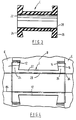
- Fig. 12 is a cross-sectional view of a pinch valve in an open position incorporating the modified casing member of Figs. 10 and 11;
- Fig. 13 is a view similar to Fig. 12 but illustrating the valve in a closed position;
- Fig. 14 is a plan of a modified reinforcing ring for incorporation into a pinch valve sleeve;
- Fig. 15 is a longitudinal sectional view of a pinch valve according to one embodiment of the invention; and
- Fig. 16 is a partially sectioned view of a modified pinch valve as substantially shown in Fig. 15 but using a manually actuated assembly.
- Referring now to the drawings, a pinch valve A has a central valve body B, a flexible elastomeric sleeve C, an actuating mechanism D, and opposed valve body end members E.
- More particularly and with reference to the embodiments of Figs. 1 and 6, the valve body is of rigid construction, preferably stainless steel. An
axial bore 10 extends through the body for receipt of the elastomeric sleeve C. First andsecond counterbores shoulder 16 with the bore. Theshoulders 16 are configured to extend axially inwardly as they extend radially outwardly away from thebore 10 to the respective counterbore sidewall. - The sleeve C includes a substantially cylindrical
central portion 22 having an outer peripheral dimension closely received in thebore 10. Enlarged radially extendingflanges central opening 28 of the sleeve. That is, the configuration of the flanges approximates to the configurations ofcounterbores - The end members E are received on opposite ends of the central valve body B to matingly engage first and
second end walls planar walls end walls first groove 42 is defined in theend wall 34 to receive seal member 44 and, likewise,second groove 46 is defined inend wall 36 to receive a seal member such as O-ring 48. The seal members provide a back-up seal arrangement between the central valve body and the end members as will become more apparent below. Since the end members are of identical construction, description of one end member will be equally applicable to the other end members unless noted otherwise. - An
enlarged portion 54 of end member E is disposed adjacent the valve body and has four substantially equally spacedopenings bolt type fasteners fourth fastener 72 extends through a lobe portion 80 of the central valve body B. The lobe portion 80 has anaxially extending opening 82 which is concentric withopenings 62 of the end members E when the valve is assembled. - As described in US-A- 3,954,251, this valve body and fastener arrangement enables the central valve body B to be swung out relative to the valve body end members E by removal of a single fastener after slackening of the other three fasteners. Particularly, removal of
fastener 66 permits the valve body B to rotate aroundfastener 72 in a counterclockwise manner as illustrated by arrow F. This structural arrangement facilitates ease of replacement of theseal members 44, 48 or provides access to the elastomeric sleeve C if replacement or maintenance is necessary. Throughout the change-over process, the central valve body B, is held in axial position relative to the end members E such that proper realignment is achieved merely by swinging the central body B back into its original position shown in Fig 2. - The end members E also have through
passages 84 which define either an inlet or an outlet to the central valve body B. Suitable connections between the through passages and an associated fluid system can be made through well known pipe or fluid connection means as conventionally used in the art. When the valve is assembled, thepassages 84 andsleeve openings 28 define a straight flow-through passage of substantially constant diameter that limits potential shearing of the biological material in the fluid and promotes laminar flow. - As illustrated in Figs. 1 and 2, a
bore 86 extends through the central valve body B and substantially perpendicular to bore 10.Counterbore 88 extends coaxially frombore 86 and defines a radial shoulder 90 therewith. The actuating mechanism D includes aclosure member 96 having a reduceddiameter tip 98 dimensioned for close receipt throughbore 86. Thetip 98 preferably has a rounded end for engagement withcylindrical portion 22 of the sleeve as will be described in greater detail below. The tip can have a blade-like configuration as apparent in Figs. 1 and 2 or a cylindrical configuration as illustrated in Figs. 6A and 6B. Still other tip configurations having a rounded end can be used without departing from the scope of the invention. - A seal member, such as O-
ring 100, is received in a peripheral groove 102 on theclosure member 96 to seal between the closure member andcounterbore 88. According to the preferred embodiment, the closure member cooperates with a biasing means such asspring 104. The spring has a first orlower end 106 received in anannular recess 108. The second orupper end 110 of the spring is received in anannular groove 120 of apiston 122 of theclosure member 96. Receipt of opposite ends of the spring in the recess and groove maintains alignment of theclosure member 96 incounterbore 88 and normally biases theclosure member 96 outwardly to a valve-open position. A seal member, such as O-ring 124, is received in aperipheral groove 126 of thepiston 122 to sealingly engage a secondenlarged counterbore 128 in the valve body B. Aclosure cap 130 is threadedly received in an upper end of the valve body B and is sealingly engaged therewith by means of yet another seal member, such as O-ring 132. Additionally, an inner end of the closure cap has a reduceddiameter recess 134 which extends outwardly from astop shoulder 136 which limits outward biasing movement of thepiston 122 andclosure member 96.Shoulder 138 defined betweencounterbores piston 122. - An
opening 140 extending from the centre of therecess 134 receives therethrough astem 142 extending outwardly from an upper face of thepiston 122. In the embodiment of Figs. 1 and 2, thestem 142 is slidably and sealingly received through theopening 140 by means ofseal member 144. Thus, aninlet 146 is also formed in the closure cap to permit fluid, such as air under pressure, to selectively enterrecess 134 and overcome the bias ofspring 104, thereby advancing thepiston 122 andclosure member 96 towards the elastomeric sleeve C. Thetip 98 is advanced against the cylindrical portion of the sleeve and "pinches" the sleeve to a closed position (Fig 6B). Removal of the air pressure frominlet 146 permits thespring 104 to bias thepiston 122 andclosure member 96 back to a normally-open position, thus restoring the tip and sleeve to the Fig. 6A position. - A
transparent shroud 148 extends outwardly from theclosure cap 130 and receives the outer end of thestem 142. In a valve-open position, thestem 142 is clearly visible through theshroud 148. On the other hand, in the valve-closed position, theclosure member 96 has moved downwardly to pinch the elastomeric valve sleeve C so that thestem 142 is not to be seen through the shroud. This provides a positive visual indication of the valve-open and valve-closed positions. - According to the modified actuator embodiment of Fig. 5, the
lateral inlet 146 is omitted from theclosure cap 130 andopening 140 is enlarged to define anannular inlet passage 150. Theshroud 148 has anopening 152 at its outer end for communication with an external fluid supply (not shown) to permit fluid flow to the upper face of thepiston 122. This arrangement provides for a dual use of theshroud 148 as both a valve-open/closed indicator and the inlet for the remote actuator system. Still further, the modified actuator arrangement eliminates the use of one sliding seal member, namely sealmember 144. In all other respects, the modified valve structure of Fig. 5 operates as described with respect to the previous embodiment. - When used in ultra-clean environments, such as the biotechnological applications discussed above, it is critical that all crevices in the fluid flow passage be eliminated to minimise the chance for entrapment of particles. To accomplish this objective, and with particular reference to Fig. 4, the unstressed configuration of the elastomeric sleeve C is illustrated in phantom while the final, assembled configuration is shown in solid lines. The axial dimension of the unstressed sleeve is somewhat greater than that of the central valve body B. When the end members E, are brought into an assembled, sealing engagement with the valve body B, the sleeve C is axially compressed which results in a number of benefits. Particularly, the cross-sectional dimension of the
sleeve opening 28 is reduced to closely approximate that ofopenings 84 in the end members E. Stated another way, axial compression of the sleeve provides a radial thickening of the sleeve to eliminate any crevices between the body and end members. An unobstructed, straight flow-through passage is thus defined by the assembled valve. - Axial compression of the sleeve C also provides a primary seal between the end members E and the valve body B. Thus,
seal members 44, 48 are secondary seals that guard against fluid loss should the elastic element rupture. They are not the primary seals. The radially outward expansion of the flanges also promotes a secure mechanical engagement between the sleeve and the valve body along theshoulders 16 of the first andsecond counterbores closure member 96 advancing and retracting between open and closed positions. - Yet another advantage is realised by the compression of the valve sleeve C. In prior arrangements a predetermined bulge was moulded into the central portion of the sleeve to accommodate the tensile forces on the sleeve by the pinch arrangement. By axially compressing the sleeve in the present invention and placing the sleeve in a compressive state, tensile forces do not arise in the sleeve until a point much later in the closing stroke of the
closure member 96. That is, the initial portion of the closing stroke transforms the sleeve from a compressive state to a neutral or non-compressive state. Further pinching of the valve sleeve during the closing stroke results in tensile forces in the valve sleeve but these tensile forces are not encountered until much later in the closing stroke than with previous structures. Thus, the overall valve design has a higher cycle life rating due to the lower tensile forces. Concurrently the pullout forces imposed on the flanges are reduced. - As is also apparent, the valve sleeve is only pinched from the upper side by the actuating mechanism as opposed to pinching from diametrically opposite sides of the sleeve. This is important from the aspect that the lower side of the valve sleeve C as shown is Figs. 1 and 2 never undergoes any cycling or deformation. In the biotechnological field it is imperative that the flow passage be not obstructed or form any traps for the fluid. By not actuating the lower portion of the valve sleeve drainability is enhanced.
- Figs. 7 and 8 illustrate a further modification to the general valve construction described above. For ease of discussion and illustration, like numerals identify like components while new numerals identify new elements. The major modification resides in the valve sleeve C and its receipt in the
axial bore 10 of the valve body. More specifically, thebore 10 is of substantially constant dimension and communicates withcounterbores seal members 44, 48 which provide the same back-up seal arrangement between the central valve body B, and the end members as described above with respect to the O-rings 44, 48 in Fig. 1. Rather than providing separate grooves in an area radially spaced from thebore 10, the modified structure permits thecounterbores - The valve sleeve C includes enlarged radially extending
flanges central portion 22. According to this embodiment, though, the flanges maintain a generally constant axial dimension as they extend radially outward fromcentral opening 28 of the sleeve. To provide the same secure mechanical engagement between the sleeve C and the valve body B, rigid metal rings 164, 166 are embedded in the sleeve flanges. More particularly, therings rings sleeve opening 28 closely approximates to that ofopenings 84 in the end members E and therings - Secondly, the metal rings 164, 166 serve the purpose of imparting sufficient rigidity to the flanges for the axial compression imposed on the sleeve C by the end members to form a primary sealing surface between the sleeve C and the end members E.
- Due to the difficulty in repairing and replacing valve sleeves C in a body configuration such as shown in the embodiment of Fig. 1, the sleeve is modified to include a second component comprising a
casing member 170. The casing member is substantially cylindrical and has an outerperipheral dimension 172 closely received in theaxial bore 10 of the valve body. Smoothly contouredrecesses constant diameter opening 178 which closely receives thecentral portion 22, of the valve sleeve C. Preferably, thecasing member 170 is formed of a material more rigid than that of the flexible valve sleeve C. By way of example only, some preferred materials of construction include plastic or metal. This provides a sufficient backup surface for the sleeve C as it is compressed axially during assembly of the valve. Thecasing member 170 also includes asidewall opening 180 which receives therounded end 98 of the closure member. - The two-part cartridge arrangement defined by the valve sleeve C and casing
member 170 facilitates ease of replacement and maintenance of the pinch valve. The substantially constant-dimensionedouter periphery 172 of the casing member permits the cartridge arrangement to be axially slid within thebore 10. The entire cartridge arrangement can be replaced as a unit and eliminates any on-site manipulation of the enlarged radial flanges of the valve sleeve as encountered with an arrangement according to Fig. 1 - In a still further modification, the outer diameter of the valve sleeve C may be provided with a support layer such as
fabric reinforcement 186. This maintains some body or form to the flexible valve sleeve C and provides a smooth transition surface between the flexible nature of the elastomeric sleeve and the more rigid construction of thecasing member 170. Alternatively, more than one support layer may be utilised if deemed necessary. - The
entire closure cap 30 in the embodiment of Fig. 7 is formed from a transparent plastic material to aid in monitoring thestem 142 of the actuating mechanism. This provides a positive indication of the valve-open or valve-closed position as described above. - In the manually actuated valve arrangements of Figs. 8 and 16, rotation of
handle 190 advances and retracts handle oractuating stem 192 relative to theclosure cap 130. The means for advancing and retracting the actuating stem results from the well-known use of an external threadedregion 194 on the stem and internaly threaded opening 196 in theclosure cap 130. Alower end 198 of theactuating stem 192, engages anupper surface 200 of thepiston 122 to advance therounded end 98 of theclosure member 96 to a closed, pinched arrangement of the valve sleeve. In the pneumatically actuated version illustrated in Fig. 7, the actuating mechanism D is axially reciprocated in response to the selective application of fluid pressure to the upper surface of the piston.Spring 104 returns the piston and actuating mechanism to a normally-open position. In order to increase valve life, and particularly the cycle life of the flexible sleeve C, in the manually actuated valve it is necessary to minimise the transmission of torque between the selectivelyrotatable actuating stem 192 and the sleeve C. Means for minimising the torque transmission is provided by the stem gimbal ordomed end 202 defined on the lower end of thestem 192. The gimbal is a substantially conical surface which provides point contact with theclosure member 96. Thus, axial advancement of theclosure member 96 is effected though the point contact without the transfer of rotary motion from theactuating stem 192 to theclosure member 96. Additionally, anactuator bearing 204 can be provided in the upper surface of the piston for engagement with the stem gimbal, as shown in Fig. 16. - Turning now to Fig. 9, the pinch valve shown there is structurally similar to the modified embodiment of Fig, 7. Therefore, like elements are identified by like numerals and new elements are identified by new numerals. The
closure member 96 also includes a reduceddiameter tip 98 having a rounded end. Unlike the blade configuration of Figs. 1 and 2 or the cylindrical configuration of Figs. 6A and 6B, the rounded tip defines a substantially horizontal,semi-cylindrical surface 210. Further reference to Figs. 12 and 13 assist in visualisation of the configuration ofsurface 210. This modified tip distributes the closing forces over a larger surface of the sidewall of the flexible sleeve. This structural arrangement provides effective closure of the valve and increases the useful life of the flexible sleeve C. - Another modification of Fig. 9 is directed to a means for venting the valve body. Specifically, the venting means is defined by a vent or weep opening 212 and the elimination of
seal member 100 from the reduceddiameter tip 98 of the closure member. This combination vents the valve body, particularly the normally sealed area defined by opening 86 andcounterbore 88 around the flexible sleeve. The venting means permits the area outside the flexible elastomer sleeve to openly communicate or breathe with the ambient environment. - Incorporation of the venting means eliminates pneumatic closure forces that arise during valve cleaning. Typically, the pinch valve is autoclaved, i.e. subject to a sterilising process that uses superheated steam under pressure. The entire valve body is subject to a temperature increase during the autoclaving process. In the embodiments illustrated in Figs. 1 to 8, the area outside the flexible sleeve is sealed from ambient air. Thus, pressure in the closed area rises as the temperature rises and the pressure imposes a pneumatic closure force on the flexible sleeve. The described venting means eliminates this undesirable action.
- Another advantage resulting from the venting means is that if the flexible sleeve C fails, leakage through the vent opening is readily detected. As illustrated in phantom in Fig. 9, a sight pipe or
tube 214 may be connected to the vent opening. The sight pipe aids in detection and to minimise spillage if a leak occurs. When processing expensive biological batches, minimising a spill can have a major economic effect and/or permit salvaging the remainder of a batch before contamination develops. - Some biological fluids cannot be leaked into the environment under any circumstances. With such constraints, it is still desirable to eliminate pneumatic closure forces. One proposed solution is to provide selective venting of the area outside the flexible sleeve. Accordingly, a valve schematically represented at 216 may be secured to the sight pipe for selective communication between the valve body interior and ambient air. By way of example, selective operation of the venting means, particularly
valve 216, provides an open path during temperature excursions such as steam-in-place autoclaving and a closed path during biological batch processing. - Referring again to Fig. 9, and with additional reference to Figs. 10 and 13, the horizontal
semi-cylindrical tip surface 210 will be described in greater detail. To accommodate this tip configuration, thecasing member 170 is modified. The sidewall opening has a substantially elongated orelliptical shape 220 to freely receive thetip 210 therethrough. A first orupper component 222 of the two-part casing member 170 maintains the smoothly contouredouter periphery 172 which is adapted for close receipt in thebore 10. Likewise, the interior shape remains substantially the same for closely receiving the flexible sleeve C, - On the other hand, the interior shape of a second or
lower component 224 of thecasing member 170 is altered to accommodate the "pinched" or closed valve sleeve C. Preferably, aplanar area 226 extends longitudinally and transversely along the interior surface of thelower component 224. The planar area provides sufficient area into which the pinched sleeve may expand. Extending the planar area longitudinally along substantially the entire casing member, that is, from end to end, prohibits formation of a dip or weir in the flexible sleeve that would impair fluid drainability through the valve. The lateral extent of the planar area decreases as it extends longitudinally from a substantially constant dimensioncentral region 228. Again, this facilitates receipt of the pinched sleeve in thelower component 224 without constricting the flow channel. Stated in another manner, the pinching action of thetip 210 is not constrained by abrupt contours in the lower component of the casing member. The flexible sleeve C deforms as a result of the pinch action of thetip 210 and not from abrupt changes in the interior shape of the lower component. - Lastly, the reinforcing or
rigid rings Apertures 230 are disposed in a predetermined pattern and extend completely through the rings. Theapertures 230 permit elastomer flow during moulding manufacture of the reinforced flexible sleeves C. The apertures, in turn, aid in bonding between the rings and flexible sleeve to provide integral, reinforcedend flanges - A means for limiting closure forces imposed on the flexible sleeve C in a pinch valve according to the invention is particularly shown in Figs. 15 and 16. The force limiting means 250 is defined by a lost
motion coupling 252 interconnecting piston or actuatingmember 122 with theclosure member 96. Relative movement between thepiston 122 and theclosure member 96 is thus permitted with the coupling. - More specifically, the
piston 122 and theclosure member 96 have been modified from the integral arrangement illustrated in Figs. 1 to 14. The modifiedpiston 122 includes astem portion 254 extending axially from a lower face of the piston. Thestem portion 254 has an axially extending slot orkeyway 256 which slidingly receives a key 258. - The
closure member 96, on the other hand, includes a recess 264 which closely receives thestem portion 254. The key 258 is fixedly secured to the closure member by aretainer 266, so that axial movement between the closure member and the piston is limited by the axial extent ofslot 256. Further,spring 268 defines a means for biasing thepiston 122 and theclosure member 96 to a first position. A first or upper end 274 of thespring 268 is received inannular groove 276 on the lower face of thepiston 122. The second orlower end 278 of the spring engages aradially extending shoulder 280 on theclosure member 96 to urge the closure member towards the flexible sleeve C. - In operation, and with reference to the air-operated pinch valve of Fig. 15, pressurised fluid is supplied to the upper face of the
piston 122 throughpassage 150. Thepiston 122 and theclosure member 96 move substantially as a unitary member towards the flexible sleeve C to close the valve. During the closing movement, thepiston 122 will bottom out in thecounterbore 128 but theclosure member 96 will not bottom out inrecess 276 of the piston. In other words, in a valve-closed position, the biasing force ofspring 268 will maintain the sleeve C in a closed position. The spring force can thus be chosen to limit crushing forces from being imposed on the flexible sleeve which might otherwise result if the closing force is dependent entirely on air operated system. - The manually-actuated embodiment of Fig. 16 operates in much the same manner. Substantially the
same actuating member 122,closure member 96, and lost motion coupling (252) can be utilised. This facilitates ease of manufacture. Thebearing 204 replaces theindicator stem 142 and the actuating or handlestem 192 operatively engages the actuating member (122) through the bearing.
Claims (26)
- A valve comprising a body (B); a flexible member (C) received in a bore (10) extending axially through said body (B) and having a passage (28) therethrough; a closure member (96) received in said body (B) for linear reciprocation transversely of said passage (28) and adapted to engage said flexible member (C) for opening and closing said passage upon retraction from and advancement towards said flexible member (C); and an actuation member (122) separate from the closure member (96) for retracting and advancing the latter;
characterised in that the actuation member (122) is linearly reciprocable in said body (B) transversely thereof between retracted and advanced positions for retracting and advancing the closure member (96) and a lost motion coupling (252) is provided between said closure member (96) and said actuation member (122) for limiting the force applied by the closure member (96) to the flexible member (C) when the actuation member (122) is actuated to its advanced position to advance the closure member (96) to close said passage (28). - A valve as claimed in claim 1, wherein said lost motion coupling (252) comprises a slot (256) and key (258) inter-connection.
- A valve as claimed in claim 1 or 2, wherein said closure member (96) is biassed relative to said actuation member (122) to limit the force applied by the closure member (96) to the flexible member (C).
- A valve as claimed in claim 1 or 2, in which said actuation member (122) operatively engages said closure member (96) through said lost-motion coupling, whereby said closure member (96) can move relative to said actuation member (122) through a predetermined range of movement.
- A valve as claimed in claim 4, wherein said actuation member (122) is biased by a spring (104) to the open or closed position.
- A valve as claimed in claim 5, wherein a second spring (268) is interposed between said actuation member (122) and said closure member (96).
- A valve as claimed in any of claims 1 to 6, wherein said actuation member comprises a piston (122).
- A valve as claimed in any of claims 1 to 6, wherein an actuating handle (190) acts on the actuation member (122) for manual operation.
- A valve as claimed in any of claims 1 to 8, further comprising means (212) for venting said body at an area encompassing said flexible member.
- A valve as claimed in claim 9, wherein said venting means (212) is provided with a valve (216) for selectively venting said body.
- A valve as claimed in any of claims 1 to 10, wherein said flexible member (C) has first and second enlarged flanges (24, 26) at its axially opposite ends, said flanges having tapered configurations which increase in axial dimension as said flanges extend radially outwardly.
- A valve as claimed in any of claims 1 to 10, wherein said flexible member (C) has first and second enlarged flanges (24, 26) at its axially opposite ends, said flanges each including a rigid ring (164, 166) disposed therein.
- A valve as claimed in claim 12, wherein said rigid rings (164, 166) have apertures (230) therethrough facilitating connection to said flanges.
- A valve as claimed in any of claims 1 to 13, wherein said flexible member (C) is axially compressed between first and second end members (E) in the assembled valve.
- A valve as claimed in claim 14, wherein said valve body (B) has a pinch opening (86) disposed substantially
perpendicular to said body opening (10) and wherein said body (B) further has a guide portion (88) extending coaxially from said pinch opening (86) and said guide portion (88) is dimensioned to receive a stem of said closure member (96) for maintaining linear movement of said closure member. - A valve as claimed in claim 15, wherein a seal member (100) is interposed between said stem of said closure member (96) and said guide portion (88).
- A valve as claimed in claim 14, 15 or 16, wherein said closure member (96) has a smooth, rounded end (98) for engaging said flexible member (C).
- A valve as claimed in claim 17, wherein said closure member (96) has a cylindrical configuration with a rounded, spherical end (98).
- A valve as claimed in claim 17, wherein said closure member (96) has a blade like configuration with a smooth, rounded end (98).
- A valve as claimed in claim 17, wherein said closure member has a substantially semi-cylindrical end (210).
- A valve as claimed in any of claims 1 to 20, wherein said actuation member (122) has an indicating stem (142) at its end remote from said closure member (96) such that said indicating stem (142) extends outwardly from said body (B) in a valve-open position.
- A valve as claimed in any of claims 1 to 21, in which a casing member (170) is received around said flexible member (C) and has an outer diametrical dimension adapted for close receipt in the axial bore (10) of said valve body (B), and said casing member (170) has an aperture (220) extending through a sidewall thereof and the closure member (96) is adapted for close receipt through said aperture (220).
- A valve as claimed in claim 21, wherein said flexible member (C) has a reinforcing layer (186) along a peripheral portion thereof.
- A valve as claimed in claim 8, wherein said handle (190) is on a handle stem (192) and means (202,204) are provided for minimising transmission of torque from said handle stem (192) to said actuation member (122).
- A valve as claimed in claim 24, wherein said torque minimising means has a substantially conical surface defined on said actuating member (122) or on said actuating stem (192).
- A valve as claimed in claim 22 or 23, wherein said casing member (170) has a planar area (226) along an interior surface thereof to accommodate lateral expansion of said flexible member (C) during valve-closure.
Applications Claiming Priority (6)
| Application Number | Priority Date | Filing Date | Title |
|---|---|---|---|
| US177971 | 1988-04-05 | ||
| US07/177,971 US4800920A (en) | 1988-04-05 | 1988-04-05 | Pinch valve |
| US07/252,257 US4877053A (en) | 1988-04-05 | 1988-09-30 | Pinch valve |
| US252257 | 1988-09-30 | ||
| US286327 | 1988-12-19 | ||
| US07/286,327 US4895341A (en) | 1988-09-30 | 1988-12-19 | Pinch valve |
Publications (3)
| Publication Number | Publication Date |
|---|---|
| EP0336663A2 EP0336663A2 (en) | 1989-10-11 |
| EP0336663A3 EP0336663A3 (en) | 1990-09-05 |
| EP0336663B1 true EP0336663B1 (en) | 1994-08-24 |
Family
ID=27390902
Family Applications (1)
| Application Number | Title | Priority Date | Filing Date |
|---|---|---|---|
| EP19890303224 Expired - Lifetime EP0336663B1 (en) | 1988-04-05 | 1989-03-31 | Valve for fluids |
Country Status (4)
| Country | Link |
|---|---|
| EP (1) | EP0336663B1 (en) |
| JP (1) | JP3049069B2 (en) |
| CA (1) | CA1327560C (en) |
| DE (1) | DE68917629T2 (en) |
Families Citing this family (10)
| Publication number | Priority date | Publication date | Assignee | Title |
|---|---|---|---|---|
| DE19936959A1 (en) * | 1999-08-05 | 2001-02-15 | Wolf Gmbh Richard | Pinch valve for medical instruments and devices |
| JP2002372159A (en) * | 2001-06-13 | 2002-12-26 | Asahi Organic Chem Ind Co Ltd | Pinch valve |
| JP4557413B2 (en) * | 2000-12-05 | 2010-10-06 | 旭有機材工業株式会社 | Pinch valve |
| DE60112893T2 (en) * | 2000-12-05 | 2006-06-14 | Asahi Organic Chem Ind | PINCH |
| JP4535650B2 (en) * | 2001-08-03 | 2010-09-01 | 旭有機材工業株式会社 | Pinch valve |
| US20120018654A1 (en) * | 2010-07-26 | 2012-01-26 | Jon Peter Wennberg | Pinch valves having a multi-piece valve body to receive flexible tubing |
| US8894035B2 (en) * | 2012-11-02 | 2014-11-25 | Oxo Fab. Inc. | Pinch valve having pivotably mounted upper and lower casings |
| KR102360588B1 (en) * | 2017-05-15 | 2022-02-08 | 카텐 컨트롤스 리미티드 | pinch valve |
| JP7202081B2 (en) * | 2018-05-31 | 2023-01-11 | 旭有機材株式会社 | pinch valve |
| JP7377009B2 (en) * | 2018-05-31 | 2023-11-09 | 旭有機材株式会社 | pinch valve |
Family Cites Families (13)
| Publication number | Priority date | Publication date | Assignee | Title |
|---|---|---|---|---|
| FR1029136A (en) * | 1950-12-06 | 1953-05-29 | Valve | |
| DE1091388B (en) * | 1956-12-13 | 1960-10-20 | Schoenebecker Brunnenfilter Ge | Shut-off device with, in particular, a replaceable hose piece made of elastic material in the housing and a flat slide as pressure piece |
| US3350053A (en) * | 1963-02-05 | 1967-10-31 | Honeywell Inc | Controlling apparatus |
| GB1099932A (en) * | 1964-06-03 | 1968-01-17 | Dunlop Rubber Co | Improved flow control valve |
| JPS436618Y1 (en) * | 1964-11-25 | 1968-03-25 | ||
| FR1512580A (en) * | 1966-12-30 | 1968-02-09 | Simplified control for pinch valve | |
| US3695576A (en) * | 1970-01-12 | 1972-10-03 | Fisher Controls Co | Reinforced boot for slurry type pinch valve |
| GB1423821A (en) * | 1972-02-18 | 1976-02-04 | Alvasum Aseptic Ltd | Flexible tubular members and valves incorporating such members |
| DD107970A2 (en) * | 1973-09-03 | 1974-08-20 | ||
| US3954251A (en) * | 1973-10-15 | 1976-05-04 | Whitey Research Tool Co. | Fluid system device |
| GB1507676A (en) * | 1974-06-27 | 1978-04-19 | Summerfield F | Flexible tubes |
| US3982724A (en) * | 1975-04-14 | 1976-09-28 | Indicon Inc. | Deformable tube material dispenser |
| DE2901275A1 (en) * | 1979-01-13 | 1980-07-24 | Sasserath & Co Kg H | CONTROL VALVE |
-
1989
- 1989-03-31 EP EP19890303224 patent/EP0336663B1/en not_active Expired - Lifetime
- 1989-03-31 DE DE1989617629 patent/DE68917629T2/en not_active Expired - Fee Related
- 1989-04-03 CA CA 595485 patent/CA1327560C/en not_active Expired - Fee Related
- 1989-04-05 JP JP1086682A patent/JP3049069B2/en not_active Expired - Lifetime
Also Published As
| Publication number | Publication date |
|---|---|
| JP3049069B2 (en) | 2000-06-05 |
| EP0336663A3 (en) | 1990-09-05 |
| JPH01299371A (en) | 1989-12-04 |
| DE68917629D1 (en) | 1994-09-29 |
| DE68917629T2 (en) | 1994-12-22 |
| CA1327560C (en) | 1994-03-08 |
| EP0336663A2 (en) | 1989-10-11 |
Similar Documents
| Publication | Publication Date | Title |
|---|---|---|
| US4895341A (en) | Pinch valve | |
| US4899783A (en) | Pinch valve | |
| US4877053A (en) | Pinch valve | |
| US6145810A (en) | Aseptic valve construction with diaphragm having straight neck | |
| CA2299913C (en) | Fluidic pinch valve system | |
| US5271426A (en) | Gate valve | |
| US5253671A (en) | High pressure diaphragm valve | |
| CA1287036C (en) | Diaphragm valve | |
| US3399695A (en) | Valve including elastomeric boot with sealing ring | |
| EP0336663B1 (en) | Valve for fluids | |
| EP0244185A2 (en) | Bellows valve | |
| US4682755A (en) | Mechanical control system in flow devices | |
| US4201366A (en) | Bellows valve | |
| GB2194312A (en) | Gate valve | |
| US5295659A (en) | Shaft seal for butterfly valve | |
| AU2018101478A4 (en) | A pinch valve | |
| JPS58166174A (en) | Ball valve and seat assembly | |
| US4955582A (en) | Weirless diaphragm valve | |
| AU631818B2 (en) | Non-rising stem valve assembly and method of replacing a permanent seal | |
| CA1315763C (en) | Double block and vent system | |
| US5238022A (en) | Internal rotary valve actuator system | |
| GB2045352A (en) | Valve operator | |
| US4800920A (en) | Pinch valve | |
| US3426998A (en) | Piston valve with o-ring seal retained by split ring | |
| US20060118753A1 (en) | Seal for a valve |
Legal Events
| Date | Code | Title | Description |
|---|---|---|---|
| PUAI | Public reference made under article 153(3) epc to a published international application that has entered the european phase |
Free format text: ORIGINAL CODE: 0009012 |
|
| AK | Designated contracting states |
Kind code of ref document: A2 Designated state(s): BE CH DE FR GB IT LI NL |
|
| PUAL | Search report despatched |
Free format text: ORIGINAL CODE: 0009013 |
|
| AK | Designated contracting states |
Kind code of ref document: A3 Designated state(s): BE CH DE FR GB IT LI NL |
|
| 17P | Request for examination filed |
Effective date: 19901015 |
|
| 17Q | First examination report despatched |
Effective date: 19920703 |
|
| GRAA | (expected) grant |
Free format text: ORIGINAL CODE: 0009210 |
|
| AK | Designated contracting states |
Kind code of ref document: B1 Designated state(s): BE CH DE FR GB IT LI NL |
|
| ITF | It: translation for a ep patent filed |
Owner name: STUDIO FERRARIO |
|
| REF | Corresponds to: |
Ref document number: 68917629 Country of ref document: DE Date of ref document: 19940929 |
|
| ET | Fr: translation filed | ||
| PLBE | No opposition filed within time limit |
Free format text: ORIGINAL CODE: 0009261 |
|
| STAA | Information on the status of an ep patent application or granted ep patent |
Free format text: STATUS: NO OPPOSITION FILED WITHIN TIME LIMIT |
|
| 26N | No opposition filed | ||
| PGFP | Annual fee paid to national office [announced via postgrant information from national office to epo] |
Ref country code: BE Payment date: 19960409 Year of fee payment: 8 |
|
| PG25 | Lapsed in a contracting state [announced via postgrant information from national office to epo] |
Ref country code: BE Effective date: 19970331 |
|
| BERE | Be: lapsed |
Owner name: WHITEY CO. Effective date: 19970331 |
|
| PGFP | Annual fee paid to national office [announced via postgrant information from national office to epo] |
Ref country code: FR Payment date: 19990302 Year of fee payment: 11 |
|
| PGFP | Annual fee paid to national office [announced via postgrant information from national office to epo] |
Ref country code: GB Payment date: 19990303 Year of fee payment: 11 |
|
| PGFP | Annual fee paid to national office [announced via postgrant information from national office to epo] |
Ref country code: DE Payment date: 19990305 Year of fee payment: 11 |
|
| PGFP | Annual fee paid to national office [announced via postgrant information from national office to epo] |
Ref country code: CH Payment date: 19990309 Year of fee payment: 11 |
|
| PGFP | Annual fee paid to national office [announced via postgrant information from national office to epo] |
Ref country code: NL Payment date: 19990318 Year of fee payment: 11 |
|
| PG25 | Lapsed in a contracting state [announced via postgrant information from national office to epo] |
Ref country code: LI Free format text: LAPSE BECAUSE OF NON-PAYMENT OF DUE FEES Effective date: 20000331 Ref country code: GB Free format text: LAPSE BECAUSE OF NON-PAYMENT OF DUE FEES Effective date: 20000331 Ref country code: CH Free format text: LAPSE BECAUSE OF NON-PAYMENT OF DUE FEES Effective date: 20000331 |
|
| PG25 | Lapsed in a contracting state [announced via postgrant information from national office to epo] |
Ref country code: NL Free format text: LAPSE BECAUSE OF NON-PAYMENT OF DUE FEES Effective date: 20001001 |
|
| REG | Reference to a national code |
Ref country code: CH Ref legal event code: PL |
|
| GBPC | Gb: european patent ceased through non-payment of renewal fee |
Effective date: 20000331 |
|
| PG25 | Lapsed in a contracting state [announced via postgrant information from national office to epo] |
Ref country code: FR Free format text: LAPSE BECAUSE OF NON-PAYMENT OF DUE FEES Effective date: 20001130 |
|
| NLV4 | Nl: lapsed or anulled due to non-payment of the annual fee |
Effective date: 20001001 |
|
| REG | Reference to a national code |
Ref country code: FR Ref legal event code: ST |
|
| PG25 | Lapsed in a contracting state [announced via postgrant information from national office to epo] |
Ref country code: DE Free format text: LAPSE BECAUSE OF NON-PAYMENT OF DUE FEES Effective date: 20010103 |
|
| PG25 | Lapsed in a contracting state [announced via postgrant information from national office to epo] |
Ref country code: IT Free format text: LAPSE BECAUSE OF NON-PAYMENT OF DUE FEES;WARNING: LAPSES OF ITALIAN PATENTS WITH EFFECTIVE DATE BEFORE 2007 MAY HAVE OCCURRED AT ANY TIME BEFORE 2007. THE CORRECT EFFECTIVE DATE MAY BE DIFFERENT FROM THE ONE RECORDED. Effective date: 20050331 |