EP0336048B1 - Verfahren und Vorrichtung zur Probenentnahme und/oder zum Einführen von Zugaben zum Inhalt von mindestens einem Behandlungstank - Google Patents
Verfahren und Vorrichtung zur Probenentnahme und/oder zum Einführen von Zugaben zum Inhalt von mindestens einem Behandlungstank Download PDFInfo
- Publication number
- EP0336048B1 EP0336048B1 EP19880402684 EP88402684A EP0336048B1 EP 0336048 B1 EP0336048 B1 EP 0336048B1 EP 19880402684 EP19880402684 EP 19880402684 EP 88402684 A EP88402684 A EP 88402684A EP 0336048 B1 EP0336048 B1 EP 0336048B1
- Authority
- EP
- European Patent Office
- Prior art keywords
- chamber
- protection
- treatment
- vessel
- cell
- Prior art date
- Legal status (The legal status is an assumption and is not a legal conclusion. Google has not performed a legal analysis and makes no representation as to the accuracy of the status listed.)
- Expired - Lifetime
Links
Images

Classifications
-
- A—HUMAN NECESSITIES
- A01—AGRICULTURE; FORESTRY; ANIMAL HUSBANDRY; HUNTING; TRAPPING; FISHING
- A01J—MANUFACTURE OF DAIRY PRODUCTS
- A01J25/00—Cheese-making
- A01J25/02—Cheese basins
Definitions
- the present invention relates to a method for taking samples and / or introducing additives to the contents of a sealed treatment tank provided with pressurization members, as well as a sampling and introduction orifice, allowing avoid recontamination of the contents of the tank when this orifice is opened by the surrounding polluted atmosphere.
- the dairy or cheese industries are a particularly representative example of the above problems.
- the first operation in the cheese-making process consists in cultivating, at the laboratory level, ferments intended to allow the coagulation or maturation of milk, by mixtures of more or less sophisticated germs; mother cultures are thus obtained which are grown in process tanks whose capacity is approximately of the order of 1000 to 60,000 liters.
- Such treatment tanks contain previously sterilized or pasteurized milk which must be brought to the temperature most favorable to the development of the cultures used by internal or external refrigeration of the process tank.
- the new medium thus cultivated is then transferred into pipes to be used in the organs of the cheese production line located downstream.
- the process tanks therefore constitute the heart of a cheese dairy: it is of course essential that the internal part of these is always maintained under sterile pressure and free of parasitic microbial germs, in order to prevent any contamination. Given the tightness of these tanks, the contamination problems arise above all when it is necessary to open the sampling and / or introduction orifice, to incorporate the mother culture, or other additives such that for example calcium chloride facilitating the coagulation of the milk, or taking samples of the contents of the treatment tank when necessary.
- the object of the present invention is to remedy the above-mentioned drawbacks by proposing a method for taking samples and / or introducing additives to the contents of a sealed treatment tank provided with pressurization members as well as a sampling and introduction orifice making it possible to reduce the risk of contamination of the contents of the tank during the opening of this orifice.
- This process is of course not limited to the case of the biological protection of the fermentation tanks of cheese factories, but can, as has been indicated, adapt to various industries, especially food, pharmaceutical or chemical.
- this process is characterized in that there is incorporated between the treatment tank and the atmosphere of the room in which it is located, a protective enclosure in which the personnel can carry out the necessary operations at the level of the content.
- tanks provided with pressurization members associated with an airlock and having an opening corresponding to the sampling and introduction orifice of the treatment tank to which it is welded in a leaktight manner at this level, the tank is brought treatment as well as the protective enclosure at a pressure higher than that of the room, the sampling and introduction orifice is opened and the pressure in the treatment tank is slightly increased so as to create between it and the 'protective enclosure, a current of air directed so as to largely exclude any contact between the treatment tank and the atmosphere of the room, and subsequently prevent contamination of the c of this during sampling operations and / or the introduction of additives.
- the enclosure isolates the mechanical parts requiring routine maintenance and prevents maintenance personnel from using tools specially assigned to the area which can be sterile, ultra-clean, explosion-proof ... a relatively large volume. low and are cost and maintenance incommensurate with the cost necessary to pressurize an entire room.
- the enclosure isolates the mechanical parts requiring routine maintenance and prevents maintenance personnel from using tools specially assigned to the area, which can be sterile, ultra-clean, explosion-proof, etc.
- the treatment tanks are not mounted in isolation, but assembled in groups consisting of generally three to eight tanks; in this case, it is advantageous to associate with a group of treatment tanks, a single protective enclosure whose geometry is chosen as a function of that of this group.
- the invention also relates to a device for implementing the above-mentioned method.
- This device is characterized in that it consists of a protective enclosure provided with pressurizing members and in which the personnel can carry out the necessary operations at the level of the contents of the tanks, this enclosure cooperating with a pre-tank serving airlock and provided with a number of openings corresponding to the number of treatment tanks with which it is associated.
- the protective enclosure as well as the pre-tank which are associated therewith often rest on feet, and have a staircase allowing staff to access it.
- the protective enclosure can be of any material, but, for practical as well as biological reasons, it is most often opted for a metal tank, in particular made of stainless steel, which has the 'advantage of being relatively inexpensive to manufacture, easy to clean, and at the same time to allow an easy tight connection by welding with the treatment tanks, at the level of the sampling and introduction orifices thereof.
- the treatment tanks are most often of essentially cylindrical shape, and are closed at their upper part by a conical end on which is pierced with the sampling and introduction orifice.
- the protective enclosure of essentially cylindrical or parallelepiped shape, is provided with at least one shoulder intended to cooperate with the conical end of the treatment tank (s) with which it is associated.
- This configuration facilitates the connection of the protective enclosure and of the treatment tank (s) at the orifices or openings thereof, and consequently makes it possible to facilitate obtaining a satisfactory seal.
- the protective enclosure is provided with a washing circuit, operating in particular in a closed circuit which comprises an introduction pipe opening at its upper part by a spray nozzle as well as a pipe outlet mounted at the bottom of this tank and preferably fitted with a siphon in order to largely prevent any contamination by outside air at this level.
- the pre-tank can also be separated from the systems and integrated upstream of the chain.
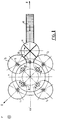
- the invention applies to a room A placed under a pressure P and containing four fermentation tanks 1, 11, 12, and 13 mounted symmetrically around a vertical axis x-x ′.
- each tank 1 the capacity of which can go up to 60,000 liters and more, rests on feet 2 and is constituted by a main part 3 approximately cylindrical closed at its upper end by a part 4 cone-shaped at the top of which is mounted a motor 5 for controlling an agitator not shown.
- the walls of the conical part 4 of the fermentation tanks 1 have an opening 6 capable of being sealed, and of being open so as to allow the taking of samples and / or the introduction of additives to the contents of the tank.
- Bodies represented schematically by the arrow B allow the pressurization of the internal part of the tank 1, as well as the introduction therein, of a stream of sterile air or neutral gas.
- the fermentation tanks 1, 11, 12, and 13 are joined, at their central part, by a protective enclosure 7 made of stainless steel which has openings 8 corresponding to the sampling orifices 6 of the fermentation tanks 1.
- the tank 7 has an essentially cylindrical or parallelepiped shape, and is provided at the conical upper part 4 of the tanks 1, with shoulders 9 having the openings 8 allowing them to be applied perfectly at this level against the side walls of the tanks 1, to which they are welded, at the periphery of the openings 8 and the orifices 6, so as to guarantee the tightness of the assembly thus formed.
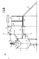
- the tank 7 is also provided with an opening 10 allowing the passage of personnel responsible for the implementation of the various operations required at the level of the tanks 1 and through which it cooperates with a pre- tank 11 acting as an airlock, in which the personnel coming from room A can enter by the staircase 12, to put on waterproof clothing, and pass through a pre-tank 13, before carrying out the various operations of additions and sampling from the contents of tanks 1 so as to minimize the risk of contamination thereof.
- a pre- tank 11 acting as an airlock, in which the personnel coming from room A can enter by the staircase 12, to put on waterproof clothing, and pass through a pre-tank 13, before carrying out the various operations of additions and sampling from the contents of tanks 1 so as to minimize the risk of contamination thereof.
- the internal part of the protective enclosure 7 is kept as clean as possible; this is, for this purpose, associated with a washing circuit comprising an introduction pipe 14 opening at its upper part by a spray nozzle 15 as well as a discharge pipe 16 mounted at the lower part of this tank 7 and provided with a siphon 17 to avoid any contamination at this level.
- Pressurization members represented diagrammatically by the arrow C (FIG. 2) make it possible to adjust the pressure prevailing in the protective enclosure 7 to a level slightly higher than that P of the room A. To have optimal protection against contamination, and avoid as much as possible any exchange of germs between the contents of the tanks 1 and the external atmosphere, it is necessary to have a continuous decrease in pressure between the fermentation tanks 1, the treatment tank 7, the pre-tank 11 and room A.
- the pressures prevailing in the fermentation tanks 1, the protective enclosure 7 and the pre-tank 11 are respectively set at values P1, P2 and P3 slightly higher than the pressure P and decreasing.
- the pressure P1 is generally 50 to 100 grams higher than the pressure P.
- the maneuver responsible for the introduction and / or sampling operations acts on the pressurization members B in order to lower the pressure P1 prevailing in the tank 1 in which it wishes to perform manipulations at the pressure P2 of the protective enclosure 7 so as to be able to open the orifice 6 for sampling and introduction and gain access to the interior of the tank; at this time, it controls the introduction into the tank 1 of a sterile air current which sweeps this tank as well as the protective enclosure 7 as shown diagrammatically by the arrow a , to prevent any passage of air in the direction reverse.
- the enclosure 7 can, moreover, be air-conditioned, insulated to adopt the temperature of the ambient atmosphere or conditioned (neutral gas) for compatibility with the product treated in the tank.
- a device of the above-mentioned type could be adapted in a particularly advantageous manner to treatment tanks located outside, to allow direct connection of these to the central body of the factory. or the laboratory and therefore provide protection from the weather for personnel handling it.
- this process in accordance with the invention, can also be adapted in the opposite direction, for example in chemistry, if the tank contains toxic or flammable products which must not come into contact with the manufacturing room.
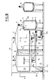
- the treatment tanks 1 and in particular, fermentation, the contents of which must be protected from any contact with the outside air, are arranged around several protective enclosures 7 and these various speakers 7 are arranged like satellites around a preparation cell 20 which is located at the same level as the protective enclosures 7 of the various groups of tanks.
- This preparation cell 20 is also located above an airlock 21 with which it communicates by a staircase, this airlock 21 constituting a disrobe in which the personnel enters by an entry door 22 provided with a pre-tank 23.
- Each tank 1 resting on feet 2 consists of a cylindrical part 3 surmounted by a conical part 4 supporting at its top an electric motor 5 driving an agitator (not shown) plunging into the tank.
- the conical part 4 of the tank 1 has an opening 6 provided with sealing means, and which is intended to be open to allow the taking of samples and / or the introduction of additives to the contents of the tank.
- B organs are intended to pressurize the internal part of each tank using sterile air or a neutral gas.
- the protective enclosure 7 of each group of tanks 1 is provided with a circular shoulder 9 comprising openings 8 fixed in a sealed manner, by welding, around the openings 6 of the tanks 1.
- Each protective enclosure 7 has an opening 24 provided with a non-sealed closure means 24 credibility allowing the passage of personnel between the preparation cell 20 and each of the enclosures 7.
- Each of the protective enclosures 7, as well as the preparation cell 20, is arranged in a washing circuit comprising a main pipe 14 for supplying disinfectant product which opens out by spray nozzles 15 and 151 respectively at the upper end of the enclosures 7 and cell 20.
- the speakers 7 and the cell 20 comprise at their lower end hydraulic siphons 17, 171 connected to a discharge pipe 16 ensuring the recovery of the washing liquid in a tank 25.
- the recovered liquid is then filtered and again disinfected in order to supply the pipe 14.
- This arrangement therefore constitutes a closed circuit enabling the speakers and the cell to be washed when this is deemed desirable.
- the enclosures 7, the tank 20 and the airlock 21 are connected to pressurization members, respectively C, D and E, the overpressures being adjusted so as to decrease from the protective enclosures 7 and up to the airlock 21 while passing by the preparation cell 20 to finish at outside atmospheric pressure.
- the overpressure of filtered air or neutral gas introduced into the tank 1, is established so as to be slightly greater than the overpressure of the enclosures 7 when the contents are taken through the opening 6. from the tank or, on the contrary, to the introduction into this tank of an additive.
- the lower end of this staircase is also, and preferably, provided with an unsealed closure device 21 beforehand.
- Staged overpressures will be determined so as to establish an air flow adjusted according to the air renewal standards which depend on the number of people present in the protective enclosures or in the preparation cell 20.
- the air overpressures of each enclosure and of the cell are controlled and regulated by various devices and, in particular, by the siphons 17 and 171, which contain a height of disinfectant in relation to the required pressure.
- This safe device has the double advantage of avoiding air overpressures in the cells or in the enclosure and allowing the disinfection, by bubbling, of the air which accidentally could be called from the outside during a depression. internal.
- siphons are fitted with devices ensuring a constant level of disinfectant liquid.
- the tank 25 as well as all of the technical organs necessary for the correct functioning of the device will be included in a technical room 27 which, in the example shown in FIG. 1, is adjacent to the airlock 21 and is arranged in- below an enclosure 7.
- Cell 20 is equipped with all the accessories compatible with environmental hygiene conditions and allowing staff to carry out medium transfer, dilution, concentration, micro-organism or any other manipulation made necessary after taking samples from tanks 1 or before introducing a additive in either of these tanks.
- This staff will have previously put on sterile clothing available to them in the airlock 21 and this before they climb into the cell 20 by the staircase 211.
- the protective enclosure 7 can serve as a link between the cell 20 and another enclosure 7, itself associated with a group of tanks 1.
- the intermediate enclosure is connected to this enclosure 71 by a passage 72 also comprising a non-sealed closure and the overpressure in the enclosure 7 is established at a level slightly lower than that of the enclosure 71 in order to produce a slight stream of air flowing by the passage 72 towards the cell 20 by the enclosure 7.
- the preparation cell 20, also called a transplanting cell can be made in civil engineering, it is preferable to make it in the form of a metal tank, in particular made of stainless steel, which has the advantage of being '' a relatively inexpensive manufacture, easy to clean, and pre-assembled in the workshop alongside the production of protective enclosures.
- the work equipment equipping the preparation cell complies with hygiene standards and air renewal is ensured according to the number of people present.
Landscapes
- Life Sciences & Earth Sciences (AREA)
- Animal Husbandry (AREA)
- Environmental Sciences (AREA)
- Apparatus For Disinfection Or Sterilisation (AREA)
- Apparatus Associated With Microorganisms And Enzymes (AREA)
Claims (16)
Priority Applications (1)
| Application Number | Priority Date | Filing Date | Title |
|---|---|---|---|
| AT88402684T ATE66114T1 (de) | 1988-04-01 | 1988-10-25 | Verfahren und vorrichtung zur probenentnahme und/oder zum einfuehren von zugaben zum inhalt von mindestens einem behandlungstank. |
Applications Claiming Priority (4)
| Application Number | Priority Date | Filing Date | Title |
|---|---|---|---|
| FR8804376 | 1988-04-01 | ||
| FR8804376A FR2629365B1 (fr) | 1988-04-01 | 1988-04-01 | Procede de prelevement d'echantillons et/ou d'introduction d'additif au contenu d'au moins une cuve de traitement etanche munie d'organes de pressurisation ainsi que d'un orifice de prelevement et d'introduction, et dispositif pour la mise en oeuvre de ce procede |
| FR8809812A FR2634395B2 (fr) | 1988-04-01 | 1988-07-20 | Procede de prelevement d'echantillons et/ou d'introduction d'additif au contenu d'au moins une cuve de traitement etanche munie d'organes de pressurisation ainsi que d'un orifice de prelevement et d'introduction et dispositif pour la mise en oeuvre de ce procede |
| FR8809812 | 1988-07-20 |
Publications (2)
| Publication Number | Publication Date |
|---|---|
| EP0336048A1 EP0336048A1 (de) | 1989-10-11 |
| EP0336048B1 true EP0336048B1 (de) | 1991-08-14 |
Family
ID=26226593
Family Applications (1)
| Application Number | Title | Priority Date | Filing Date |
|---|---|---|---|
| EP19880402684 Expired - Lifetime EP0336048B1 (de) | 1988-04-01 | 1988-10-25 | Verfahren und Vorrichtung zur Probenentnahme und/oder zum Einführen von Zugaben zum Inhalt von mindestens einem Behandlungstank |
Country Status (3)
| Country | Link |
|---|---|
| EP (1) | EP0336048B1 (de) |
| DE (1) | DE3864256D1 (de) |
| FR (1) | FR2634395B2 (de) |
Family Cites Families (3)
| Publication number | Priority date | Publication date | Assignee | Title |
|---|---|---|---|---|
| US2746847A (en) * | 1952-11-20 | 1956-05-22 | Swift & Co | Provolone and cacciacavallo cheese manufacture |
| US3907389A (en) * | 1973-12-12 | 1975-09-23 | Marion E Cox | Glove box chamber |
| US3988011A (en) * | 1975-09-18 | 1976-10-26 | Kusel Equipment Company | Food processing apparatus |
-
1988
- 1988-07-20 FR FR8809812A patent/FR2634395B2/fr not_active Expired - Lifetime
- 1988-10-25 DE DE8888402684T patent/DE3864256D1/de not_active Expired - Fee Related
- 1988-10-25 EP EP19880402684 patent/EP0336048B1/de not_active Expired - Lifetime
Also Published As
| Publication number | Publication date |
|---|---|
| DE3864256D1 (de) | 1991-09-19 |
| FR2634395B2 (fr) | 1991-02-22 |
| FR2634395A2 (fr) | 1990-01-26 |
| EP0336048A1 (de) | 1989-10-11 |
Similar Documents
| Publication | Publication Date | Title |
|---|---|---|
| EP1230990B1 (de) | Aseptische Ventilanordnung | |
| EP3108974A1 (de) | Desinfektionsnebelüberflutungssystem und verfahren sowie verfahren zur desinfektion von innenflächen von aseptischen behältern und rohrleitungen | |
| EP0336048B1 (de) | Verfahren und Vorrichtung zur Probenentnahme und/oder zum Einführen von Zugaben zum Inhalt von mindestens einem Behandlungstank | |
| JPH02302257A (ja) | 殺菌充填装置のヘッドスペースの殺菌洗浄方法およびこの方法を実施するための装置 | |
| US20090246074A1 (en) | System and method for sterilizing a processing line | |
| KR100936834B1 (ko) | 벌크 살균 생산물을 무균적으로 저장하는 방법 | |
| US6514550B1 (en) | Method and system for carrying out the disinfestation of products by means of the use of gas under atmospheric pressure with pretreatment in vacuo | |
| US3871824A (en) | Method of aseptically connecting a fitting to an aseptic storage tank | |
| EP0290139A2 (de) | Vorrichtung zum Sterilisieren von Folienbahnen und solchem Verpackungsmaterial | |
| US4294271A (en) | Apparatus for removing deposited matter from a diffusion tube | |
| US3951184A (en) | Method of filling, sampling and sealing an aseptic tank with sterile product without destroying asepsis of either the sterile product or the tank and its associated valves and fittings | |
| FR3089960A1 (fr) | Unité d’embouteillage boissons | |
| FR2629365A1 (fr) | Procede de prelevement d'echantillons et/ou d'introduction d'additif au contenu d'au moins une cuve de traitement etanche munie d'organes de pressurisation ainsi que d'un orifice de prelevement et d'introduction, et dispositif pour la mise en oeuvre de ce procede | |
| US4047547A (en) | Method of filling, sampling and sealing an aseptic tank | |
| JP2001228064A (ja) | 無菌状態監視用サンプリング装置 | |
| JP5030701B2 (ja) | サンプリング容器用蓋を用いたサンプリング方法 | |
| EP1858338A1 (de) | Systemisches verfahren für umgebungshygiene und vorrichtung mit niedrigtemperturdesinfektionskammer, v.a. für nahrungsmittelprodukte | |
| JP7326568B1 (ja) | サンプリングシステム | |
| US3714956A (en) | Aseptic storage and valving system | |
| GB2385322A (en) | A safety container for metallo-organic substances | |
| DE10213343A1 (de) | Vorrichtung und Verfahren für kaltsterile Abfüllung und Verschluß von Behältern | |
| FR2705896A1 (fr) | Dispositif de décontamination, désinfection et séchage des endoscopes étanches. | |
| US6919032B2 (en) | Distribution/retention plate for minimizing off-gassing | |
| US3630226A (en) | Anaerobic storage apparatus | |
| JPH01179682A (ja) | 培養槽及びその洗浄方法 |
Legal Events
| Date | Code | Title | Description |
|---|---|---|---|
| PUAI | Public reference made under article 153(3) epc to a published international application that has entered the european phase |
Free format text: ORIGINAL CODE: 0009012 |
|
| AK | Designated contracting states |
Kind code of ref document: A1 Designated state(s): AT BE CH DE ES GB GR IT LI LU NL SE |
|
| 17P | Request for examination filed |
Effective date: 19891102 |
|
| 17Q | First examination report despatched |
Effective date: 19901029 |
|
| GRAA | (expected) grant |
Free format text: ORIGINAL CODE: 0009210 |
|
| AK | Designated contracting states |
Kind code of ref document: B1 Designated state(s): AT BE CH DE ES GB GR IT LI LU NL SE |
|
| PG25 | Lapsed in a contracting state [announced via postgrant information from national office to epo] |
Ref country code: IT Free format text: LAPSE BECAUSE OF FAILURE TO SUBMIT A TRANSLATION OF THE DESCRIPTION OR TO PAY THE FEE WITHIN THE PRESCRIBED TIME-LIMIT;WARNING: LAPSES OF ITALIAN PATENTS WITH EFFECTIVE DATE BEFORE 2007 MAY HAVE OCCURRED AT ANY TIME BEFORE 2007. THE CORRECT EFFECTIVE DATE MAY BE DIFFERENT FROM THE ONE RECORDED. Effective date: 19910814 Ref country code: SE Effective date: 19910814 Ref country code: AT Effective date: 19910814 Ref country code: NL Effective date: 19910814 Ref country code: GR Free format text: LAPSE BECAUSE OF FAILURE TO SUBMIT A TRANSLATION OF THE DESCRIPTION OR TO PAY THE FEE WITHIN THE PRESCRIBED TIME-LIMIT Effective date: 19910814 Ref country code: ES Free format text: THE PATENT HAS BEEN ANNULLED BY A DECISION OF A NATIONAL AUTHORITY Effective date: 19910814 Ref country code: GB Effective date: 19910814 |
|
| REF | Corresponds to: |
Ref document number: 66114 Country of ref document: AT Date of ref document: 19910815 Kind code of ref document: T |
|
| REF | Corresponds to: |
Ref document number: 3864256 Country of ref document: DE Date of ref document: 19910919 |
|
| PG25 | Lapsed in a contracting state [announced via postgrant information from national office to epo] |
Ref country code: LI Effective date: 19911031 Ref country code: CH Effective date: 19911031 Ref country code: LU Free format text: LAPSE BECAUSE OF NON-PAYMENT OF DUE FEES Effective date: 19911031 Ref country code: BE Effective date: 19911031 |
|
| NLV1 | Nl: lapsed or annulled due to failure to fulfill the requirements of art. 29p and 29m of the patents act | ||
| GBV | Gb: ep patent (uk) treated as always having been void in accordance with gb section 77(7)/1977 [no translation filed] | ||
| BERE | Be: lapsed |
Owner name: S.A. GOAVEC Effective date: 19911031 |
|
| PLBE | No opposition filed within time limit |
Free format text: ORIGINAL CODE: 0009261 |
|
| STAA | Information on the status of an ep patent application or granted ep patent |
Free format text: STATUS: NO OPPOSITION FILED WITHIN TIME LIMIT |
|
| REG | Reference to a national code |
Ref country code: CH Ref legal event code: PL |
|
| PG25 | Lapsed in a contracting state [announced via postgrant information from national office to epo] |
Ref country code: DE Effective date: 19920701 |
|
| 26N | No opposition filed |