EP0336006A2 - Wall feed through - Google Patents
Wall feed through Download PDFInfo
- Publication number
- EP0336006A2 EP0336006A2 EP88114175A EP88114175A EP0336006A2 EP 0336006 A2 EP0336006 A2 EP 0336006A2 EP 88114175 A EP88114175 A EP 88114175A EP 88114175 A EP88114175 A EP 88114175A EP 0336006 A2 EP0336006 A2 EP 0336006A2
- Authority
- EP
- European Patent Office
- Prior art keywords
- flange
- wall
- packing
- casing
- traction means
- Prior art date
- Legal status (The legal status is an assumption and is not a legal conclusion. Google has not performed a legal analysis and makes no representation as to the accuracy of the status listed.)
- Withdrawn
Links
Images
Classifications
-
- H—ELECTRICITY
- H02—GENERATION; CONVERSION OR DISTRIBUTION OF ELECTRIC POWER
- H02G—INSTALLATION OF ELECTRIC CABLES OR LINES, OR OF COMBINED OPTICAL AND ELECTRIC CABLES OR LINES
- H02G3/00—Installations of electric cables or lines or protective tubing therefor in or on buildings, equivalent structures or vehicles
- H02G3/22—Installations of cables or lines through walls, floors or ceilings, e.g. into buildings
Definitions
- the invention relates to a wall bushing for lines, such as cables, pipes or the like, for insertion into a wall opening, with a casing pipe penetrating the wall opening, a packing for filling the annular space between the casing pipe and the wall opening and with two axially on both sides of the packing flanges seated on the casing, of which one flange is arranged outside the wall opening and set up for sealing against the outside of the wall and the other flange for the axial pressing of the packing is arranged displaceably within the wall opening and is supported against the axial pressure of the packing, for which purpose between the latter
- a locking device is provided for the flange and the casing, which only allows displacements of the flange on the casing in the direction of the packing, but blocks the flange against displacement in the opposite direction.
- Wall bushings of this type are known from the patent application DE 37 31 583, which does not belong to the previously published prior art. With them, the inner flange is under the force of a spring that presses the flange against the packing so that the packing is compressed in the breakthrough of the wall and the casing against the reveal of the wall breakthrough seals. To do this, unlock the initially tensioned spring so that it can relax and act on the pack.
- this unlocking is carried out in such a way that a packing ring on the casing, which closes the flange towards the flange, is held in a detent seat against the force of the spring, from which the packing ring can only be released when it is spread out, with what A clamping nut provided on the outside in front of the outer flange is possible, which can be screwed into an external thread provided on the casing.
- a disadvantage of this embodiment is the fact that when the clamping nut is screwed on it is not recognizable from the outside whether the packing ring has really unlocked the inner flange and thus the spring and the spring has relaxed accordingly, that is to say the pack has been sufficiently compressed.
- the invention has for its object to provide a wall bushing of the type mentioned in such a way that the pack can be compressed as desired in a precisely controllable manner and with respect to the scope.
- flange located within the wall opening is connected to a traction means which is sealed between the casing on the one hand and the packing and the outer flange on the other hand and is axially movably guided to the outside and on the outside in front of the outside Flange is accessible.
- the inner flange By pulling manually on the externally accessible traction means, the inner flange can be moved against the pack and the pack can be compressed, the path by which and the force with which the compression takes place, if desired, precisely via the traction path and the Traction of the traction device can be measured and controlled.
- the wall bushing according to the invention is of a considerably simpler construction, since the spring and the unlocking device for the spring are dispensed with.
- the traction means is preferably a band which lies flat against the casing. If the tape is thin, for example made of tear-resistant plastic, it does not wear much on the casing and does not impair the sealing effect of the pack.
- a particularly simple and safe handling of the traction device results if, according to a further proposal of the invention, the traction device is guided in a loop, the two traction device ends being connected to the flange and the loop apex lying in front of the outer flange.
- the ends of the traction means are expediently connected to the inner flange at diametrically opposite locations and run diametrically opposite one another axially on the casing.
- the traction means is held in a detent seat on the inner flange and the detent seat is released and the traction means is released when the tractive force of the traction means exceeds a predetermined size.
- the traction means has a predetermined breaking point in front of the inner flange, which breaks when the tractive force of the traction means exceeds a predetermined size. In any case, it is achieved that the traction device can be completely pulled out of the wall duct after releasing it from the resting seat or tearing the predetermined breaking point before the packing pre-compressed with the aid of the inner flange is finally clamped from the outside.
- a preferred embodiment is characterized in that the casing has a longitudinal groove on the outside in the area of the external thread in which the traction means runs.
- the traction device is expediently adapted to the profile cross section of the longitudinal groove and fills the groove cross section.
- the wall bushing shown in the drawing for lines not shown, such as cables, pipes or the like, has a casing 1 which is inserted into a wall opening of a wall, not shown in the drawing, preferably designed as a hole.
- the wall duct has a packing 2 filling the annular space between the casing 1 and the reveal of the wall opening and two flanges 3, 4 on both sides of this packing 2 on the outside of the casing 1.
- the flange 3 on the left in the drawing is for sealing against the outside of the wall is set up, for which he has a cross-section of the wall breakthrough radially everywhere and is coated on its side facing the wall with an adhesive or self-sealing sealant 6, which seals the surface of the wall, for example a sealing paint provided there or can connect a waterproofing membrane in a watertight and gas-tight manner.
- the flange 3 is arranged longitudinally displaceably on the casing 1 and on a Axially supported clamping nut 7, which can be screwed into an external thread 8 provided on the casing tube 1 and extending from the left tube end.
- the other flange 4 on the right in the drawing serves to axially compress the packing 2 within the wall opening and can be displaced in the wall opening at least over part of the opening length, but it is always against the axial pressure of the packing 2 in a manner to be described on the casing 1 is supported.
- the packing 2 consists of a series of packing rings 2.2 which can be expanded in diameter and which are supported against one another by means of coaxial conical surfaces 11 with a cone angle which avoids self-locking and which, when the packing 2 is pressed together, axially collapse on the conical surfaces and thereby expand radially.
- the conical surfaces 11 each end at their larger diameter end in an annular shoulder 12 projecting radially outwards beyond the conical surface, against which they come to rest when they have completely pushed together in their conical surfaces 11. So that they can not slip in the ring shoulders 12 from each other, the ring shoulders of adjacent packing rings are set up for radial positive engagement with each other, which is achieved in the exemplary embodiment in that the ring shoulder on the cone outer surface undercut dovetail and the ring shoulder on the cone inner surface with one in Undercut, axially projecting dovetail profile is equipped.
- the packing rings are axially slotted to allow them to expand radially.
- the slots 13 of adjacent packing rings are offset from one another in the circumferential direction.
- the packing rings 2 are further provided on its outer peripheral surface with a circumferential surface profile 14, which is formed in the exemplary embodiment as a pointed-toothed grooving. This surface profiling 14 ensures good adhesion of the pack 2 pressed into the wall opening with the wall of the wall opening.
- the first packing ring 2 on the side of the clamping nut 7 has an inner cone surface which opens towards the clamping nut and into which a collar 15 provided with a corresponding conical outer surface engages, which can be clamped axially against the packing 2.
- the conical outer surface 15 of this collar 15 ends on the tension nut side in a radially projecting beyond the conical outer surface annular shoulder 15.2, which can come to rest on an annular shoulder 12 'of the packing ring 2 and then prevents the collar 15 and the first packing ring 2 lying against it from becoming too wide can slide over each other.
- the collar 15 is axially supported on the clamping nut 7 and is formed as part of the outer flange 3 on the clamping nut side.
- the flange 3 has an outer washer 3.1 intended for abutment on the outside of the wall, which surrounds the collar 15 at a distance, and is tightly connected to the collar 15 by a ring part 3.2, which enables the collar 15 and the washer 3.1 to be adjusted against one another by their own deformation , so that the washer 3.1 can also lie over its entire circumference on the outside of the wall when the axis of the casing 1 should not be perpendicular to the outside of the wall.
- the ring part 3.2 is designed in cross section as a channel profile and with the collar 15 and Ring disk 3.1 made in one piece from rubber or another suitable elastomeric plastic.
- This choice of material also enables the ring washer, for example, to create a sealing around the entire circumference of a wall outside which is not absolutely planar. If the collar 15 is pressed against the packing 8, it experiences a radially inward tension against the casing 1 in the inner cone surface of the packing ring 2, as a result of which the tight fit between the flange 3 and the casing 1 results.
- a locking device is provided between the casing 1 and the flange 4 displaceable in the breakthrough of the wall, which enables displacements of the flange 4 on the casing 1 only in the direction of the pack 2 and the outer flange 3, but blocks the flange 4 against displacements in the opposite direction.
- the inner flange 4 lies in the direction of its displaceability on the right last packing ring 2. It is axially slotted with respect to its circumference and can thus be resiliently spread in diameter.
- On the casing 1 over the displacement area of the flange 4 adjacent ring grooves 19 are provided, which have a sawtooth profile, the steep, in a plane perpendicular to the casing axis tooth face 19 'of the profile facing the outer flange 3 and the clamping nut 7.
- the flange 4 has on its inner circumferential surface an annular web 20 engaging in the annular groove 19 with a saw tooth profile corresponding to the annular grooves 19. As a result, the flange 4 can be moved to the left in the drawing, whereby it spreads over the inclined tooth flanks until it over the tooth face 19 'in the next Ring groove 19 jumps in. A corresponding movement of the flange 4 in the opposite direction, that is, to the right in the drawing, prevents the steep tooth face 19 '.
- the inner flange 4 is connected to a traction means 25 which is sealed between the casing 1 on the one hand and the packing 2 and the outer flange 3 on the other hand and is axially movably guided to the outside, so that it is on the outside in front of the outer flange 3 and the clamping nut 7 is accessible.
- the traction means 25 is a band that lies flat against the casing 1. It is guided in a loop, the two ends of the traction means 25 ', 25' are connected to the flange 4 and the loop apex 26 'lies in front of the outer flange 3 and the clamping nut 8.
- the traction ends 25 ', 25 ⁇ are connected to diametrically opposite points on the inner flange 4.
- the traction means 25 is held in a snap fit on the inner flange 4.
- This locking seat is formed by a locking head 28 at the traction end 25 ', 25, and a resiliently opening and then releasing the locking head locking receptacle 29 on the flange 4, the locking receptacle 29 then releasing the locking head 28 when the tractive force of the traction means 25 is a predetermined size exceeds.
- the traction means 25 can have a predetermined breaking point 30 close to the inner flange 4, which breaks when the traction force of the traction means 25 exceeds a predetermined size.
- the casing 1 is provided on the outside with a longitudinal groove 27, in which the traction means 25 passes under the clamping nut 7.
- the profile of the traction means is essentially matched to the profile cross section of the longitudinal groove 27 and fills the groove cross section.
- the wall bushing used in the wall opening is aligned so that the outer flange 3 abuts the outer wall surface.
- the inner flange 4 is moved axially against the packing 2 by pulling on the traction means 25, the packing rings 2 sliding axially one above the other and the packing 2 being compressed as a result. If the pack 2 is sufficiently pre-compressed in the breakthrough of the wall, a further increase in tractive force on the traction means 25 can result in the traction means ends 25 ', 25' detaching from the inner flange 4 and the traction means 25 being able to be pulled completely out of the wall duct.
- the final bracing of the wall duct is carried out with the help of the clamping nut 7, when tightening the casing 1 between the outer flange and the inner flange 4 serves as a tie rod, so that the two flanges 3, 4 are further approximated to one another and thus the packing finally in the wall breakthrough is tensioned.
Abstract
Description
Die Erfindung betrifft eine Mauerdurchführung für Leitungen, wie Kabel, Rohre oder dergleichen, zum Einsetzen in einen Mauerdurchbruch, mit einem den Mauerdurchbruch durchgreifenden Futterrohr, einer Packung zum Ausfüllen des Ringraumes zwischen dem Futterrohr und der Wandung des Mauerdurchbruchs und mit zwei axial beidseits der Packung auf dem Futterrohr sitzenden Flanschen, von denen der eine Flansch außerhalb des Mauerdurchbruchs angeordnet und zur Abdichtung gegen die Außenseite der Mauer eingerichtet und der andere Flansch zum axialen Verpressen der Packung innerhalb des Mauerdurchbruchs verschiebbar angeordnet und gegen den axialen Druck der Packung abgestützt ist, wozu zwischen diesem Flansch und dem Futterrohr eine Sperreinrichtung vorgesehen ist, die Verschiebungen des Flansches auf dem Futterrohr nur in Richtung zur Packung hin ermöglicht, den Flansch gegen Verschiebung in entgegengesetzter Richtung aber sperrt.The invention relates to a wall bushing for lines, such as cables, pipes or the like, for insertion into a wall opening, with a casing pipe penetrating the wall opening, a packing for filling the annular space between the casing pipe and the wall opening and with two axially on both sides of the packing flanges seated on the casing, of which one flange is arranged outside the wall opening and set up for sealing against the outside of the wall and the other flange for the axial pressing of the packing is arranged displaceably within the wall opening and is supported against the axial pressure of the packing, for which purpose between the latter A locking device is provided for the flange and the casing, which only allows displacements of the flange on the casing in the direction of the packing, but blocks the flange against displacement in the opposite direction.
Mauerdurchführungen dieser Art sind aus der nicht zum vorveröffentlichten Stand der Technik gehörenden Patentanmeldung DE 37 31 583 bekannt. Bei ihnen steht der innere Flansch unter der Kraft einer Feder, die den Flansch gegen die Packung drückt, damit die Packung im Mauerdurchbruch gestaucht wird und das Futterrohr gegen die Leibung des Mauerdurchbruchs abdichtet. Dazu ist die zunächst gespannte Feder zu entsperren, damit sie sich entspannen und dabei die Packung beaufschlagen kann. Im einzelnen erfolgt diese Entsperrung in der Weise, daß ein die Packung zum Flansch hin abschließender, dem Flansch anliegender Packungsring am Futterrohr gegen die Kraft der Feder in einem Rastsitz gehalten ist, aus dem sich der Packungsring nur löst, wenn er aufgespreizt wird, was mit Hilfe einer außen vor dem äußeren Flansch vorgesehenen Spannmutter möglich ist, die in einem auf dem Futterrohr vorhandenen Außengewinde verschraubbar ist. Nachteilig bei dieser Ausführungsform ist der Umstand, daß beim Verschrauben der Spannmutter nicht von außen erkennbar ist, ob der Packungsring den inneren Flansch und damit die Feder wirklich entsperrt und die Feder sich entsprechend entspannt hat, die Packung also ausreichend gestaucht worden ist.Wall bushings of this type are known from the patent application DE 37 31 583, which does not belong to the previously published prior art. With them, the inner flange is under the force of a spring that presses the flange against the packing so that the packing is compressed in the breakthrough of the wall and the casing against the reveal of the wall breakthrough seals. To do this, unlock the initially tensioned spring so that it can relax and act on the pack. In particular, this unlocking is carried out in such a way that a packing ring on the casing, which closes the flange towards the flange, is held in a detent seat against the force of the spring, from which the packing ring can only be released when it is spread out, with what A clamping nut provided on the outside in front of the outer flange is possible, which can be screwed into an external thread provided on the casing. A disadvantage of this embodiment is the fact that when the clamping nut is screwed on it is not recognizable from the outside whether the packing ring has really unlocked the inner flange and thus the spring and the spring has relaxed accordingly, that is to say the pack has been sufficiently compressed.
Der Erfindung liegt die Aufgabe zugrunde, eine Mauerdurchführung der eingangs genannten Art so auszubilden, daß die Packung in genau kontrollierbarer Weise und bezüglich des Umfangs ganz nach Wunsch gestaucht werden kann.The invention has for its object to provide a wall bushing of the type mentioned in such a way that the pack can be compressed as desired in a precisely controllable manner and with respect to the scope.
Diese Aufgabe wird nach der Erfindung dadurch gelöst, daß der innerhalb des Mauerdurchbruchs befindliche Flansch an ein Zugmittel angeschlossen ist, das zwischen dem Futterrohr einerseits und der Packung sowie dem äußeren Flansch andererseits abgedichtet und axial beweglich nach außen geführt ist und auf der Außenseite vor dem äußeren Flansch zugänglich ist.This object is achieved according to the invention in that the flange located within the wall opening is connected to a traction means which is sealed between the casing on the one hand and the packing and the outer flange on the other hand and is axially movably guided to the outside and on the outside in front of the outside Flange is accessible.
Durch Zug von Hand am von außen zugänglichen Zugmittel kann der innere Flansch gegen die Packung bewegt und dabei die Packung gestaucht werden, wobei der Weg, um den- , und die Kraft, mit der die Stauchung erfolgt, nach Wunsch genau über den Zugweg und die Zugkraft des Zugmittels bemessen und kontrolliert werden können. Darüber hinaus ist die erfindungsgemäße Mauerdurchführung von wesentlich einfacherem Aufbau, da die Feder und die Entsperreinrichtung für die Feder entfallen.By pulling manually on the externally accessible traction means, the inner flange can be moved against the pack and the pack can be compressed, the path by which and the force with which the compression takes place, if desired, precisely via the traction path and the Traction of the traction device can be measured and controlled. In addition, the wall bushing according to the invention is of a considerably simpler construction, since the spring and the unlocking device for the spring are dispensed with.
Vorzugsweise ist das Zugmittel ein Band, das dem Futterrohr flach anliegt. Ist das Band dünn, beispielsweise aus reißfestem Kunststoff, trägt es entsprechend wenig am Futterrohr auf und beeinträchtigt nicht die Dichtwirkung der Packung.The traction means is preferably a band which lies flat against the casing. If the tape is thin, for example made of tear-resistant plastic, it does not wear much on the casing and does not impair the sealing effect of the pack.
Eine besonders einfache und sichere Handhabung des Zugmittels ergibt sich dann, wenn nach einem weiteren Vorschlag der Erfindung das Zugmittel in einer Schlaufe geführt ist, wobei die beiden Zugmittelenden an den Flansch angeschlossen sind und der Schlaufenscheitel vor dem äußeren Flansch liegt. Die Zugmittelenden sind zweckmäßig an einander diametral gegenüberliegenden Stellen an den inneren Flansch angeschlossen und verlaufen, diametral sich gegenüberliegend, axial auf dem Futterrohr.A particularly simple and safe handling of the traction device results if, according to a further proposal of the invention, the traction device is guided in a loop, the two traction device ends being connected to the flange and the loop apex lying in front of the outer flange. The ends of the traction means are expediently connected to the inner flange at diametrically opposite locations and run diametrically opposite one another axially on the casing.
Es empfiehlt sich, die Anordnung im übrigen so zu treffen, daß das Zugmittel in einem Rastsitz am inneren Flansch gehalten ist und der Rastsitz sich löst und das Zugmittel freigibt, wenn die Zugkraft des Zugmittels eine vorgegebene Größe überschreitet. Statt dessen oder zusätzlich besteht auch die Möglichkeit, daß das Zugmittel dicht vor dem inneren Flansch eine Sollbruchstelle aufweist, die reißt, wenn die Zugkraft des Zugmittels eine vorgegebene Größe überschreitet. In jedem Fall wird dadurch erreicht, daß das Zugmittel nach dem Lösen aus dem Rastsitz bzw. Reißen der Sollbruchstelle völlig aus der Mauerdurchführung herausgezogen werden kann, bevor die mit Hilfe des inneren Flansches vorgestauchte Packung endgültig von außen verspannt wird. Ist zur Durchführung dieser abschließenden Verspannung der äußere Flansch gegen eine Spannmutter abgestützt, die auf einem auf dem Futterrohr vorgesehenen Außengewinde verschraubbar ist, so ist eine bevorzugt Ausführungsform dadurch gekennzeichnet, daß das Futterrohr im Bereich des Außengewindes außenseitig eine Längsnut aufweist in der das Zugmittel verläuft. Das Zugmittel ist zweckmäßig dem Profilquerschnitt der Längsnut angepaßt und füllt den Nutquerschnitt aus.It is advisable to make the arrangement so that the traction means is held in a detent seat on the inner flange and the detent seat is released and the traction means is released when the tractive force of the traction means exceeds a predetermined size. Instead of or in addition there is also the possibility that the traction means has a predetermined breaking point in front of the inner flange, which breaks when the tractive force of the traction means exceeds a predetermined size. In any case, it is achieved that the traction device can be completely pulled out of the wall duct after releasing it from the resting seat or tearing the predetermined breaking point before the packing pre-compressed with the aid of the inner flange is finally clamped from the outside. If, for carrying out this final bracing, the outer flange is supported against a clamping nut which can be screwed onto an external thread provided on the casing, a preferred embodiment is characterized in that the casing has a longitudinal groove on the outside in the area of the external thread in which the traction means runs. The traction device is expediently adapted to the profile cross section of the longitudinal groove and fills the groove cross section.
Die Sperreinrichtung, welche Verschiebungen des inneren Flansches in von der Packung abgewandter Richtung verhindert, ist zweckmäßig in der Weise ausgebildet, daß der innere Flansch bezüglich seines Umfangs axial geschlitzt und dadurch im Durchmesser federnd aufspreizbar ist, daß auf dem Futterrohr über den Verschiebungsbereich des Flansches neben einander liegende Ringnuten von sägezahnförmigem Profil vorgesehen sind, wobei die steile Zahnbrust des Profils der Packung zugewandt ist, und daß der Flansch einen in die Ringnuten eingreifenden Ringsteg mit den Ringnuten entsprechendem Sägezahnprofil aufweist. Die die Packung stauchende Bewegung des Flansches mit Hilfe des Zugmittels bleibt durch die so ausgebildete Sperreinrichtung unbehindert. Im folgenden wird die Erfindung an einem in der Zeichnung dargestellten Ausführungsbeispiel näher erläutert; es zeigen:
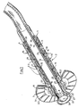
- Fig. 1 eine Mauerdurchführung nach der Erfindung in einer Schrägansicht, teils im Schnitt,
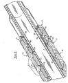
- Fig. 2 die Durchführung nach Fig. 1 in einer vergrößerten Teildarstellung, und
- Fig. 3 eine Schrägansicht eines Teils des inneren Flansches und des daran angeschlossenen Zugmittels, teils geschnitten, in einer gegenüber Fig. 2 etwas vergrößerten Darstellung.
- 1 is a wall bushing according to the invention in an oblique view, partly in section,
- Fig. 2 shows the implementation of FIG. 1 in an enlarged partial view, and
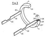
- Fig. 3 is an oblique view of part of the inner flange and the traction device connected to it, partly in section, in a somewhat enlarged representation compared to FIG. 2.
Die in der Zeichnung dargestellte Mauerdurchführung für nicht gezeichnete Leitungen, wie Kabel, Rohre oder dergleichen, besitzt ein Futterrohr 1, das in einen vorzugsweise als Bohrung ausgeführten Mauerdurchbruch einer in der Zeichnung nicht dargestellten Mauer eingesetzt wird. Die Mauerdurchführung besitzt eine den Ringraum zwischem dem Futterrohr 1 und der Laibung des Mauerdurchbruchs ausfüllende Packung 2 und zwei beidseits dieser Packung 2 außen auf dem Futterrohr 1 sitzende Flansche 3, 4. Von diesen beiden Flanschen ist der in der Zeichnung linke Flansch 3 zur Abdichtung gegen die Außenseite der Mauer eingerichtet, wozu er eine den Querschnitt des Mauerdurchbruchs überall radial übergreifende Größe besitzt und auf seiner der Mauer zugewandten Seite mit einer klebenden oder selbstverschweißenden Dichtmasse 6 beschichtet ist, die sich dichtend mit der Oberfläche der Mauer, beispielsweise einem dort vorgesehenen Dichtanstrich oder einer Dichtbahn wasser- und gasdicht verbinden kann. Der Flansch 3 ist auf dem Futterrohr 1 längsverschiebbar angeordnet und an einer Spannmutter 7 axial abgestützt, die in einem auf dem Futterrohr 1 vorgesehenen, vom linken Rohrende ausgehenden Außengewinde 8 verschraubbar ist. Der andere, in der Zeichnung rechte Flansch 4 dient zum axialen Stauchen der Packung 2 innerhalb des Mauerdurchbruchs und ist im Mauerdurchbruch zumindest über einen Teil der Durchbruchslänge verschiebbar, wobei er aber immer gegen den axialen Druck der Packung 2 in noch zu beschreibender Weise am Futterrohr 1 abgestützt ist. Die Packung 2 besteht aus einer Reihe von im Durchmesser spreizbaren Packungsringen 2.2, die über koaxiale Kegelflächen 11 mit einem die Selbsthemmung vermeidenden Kegelwinkel gegeneinander abgestützt sind und sich beim Verpressen der Packung 2 an den Kegelflächen axial zusammenschieben und dabei radial erweitern. Die Kegelflächen 11 enden an ihrem im Durchmesser größeren Ende jeweils in einer radial nach außen über die Kegelfläche vorstehenden Ringschulter 12, an der sie aneinander zur Anlage kommen, wenn sie sich in ihren Kegelflächen 11 vollständig zusammengeschoben haben. Damit sie dabei in den Ringschultern 12 nicht von einander abrutschen können, sind die Ringschultern benachbarter Packungsringe zum radial formschlüssigen Eingriff aneinander eingerichtet, was im Ausführungsbeispiel dadurch erzielt wird, daß die Ringschulter an der Kegelaußenfläche schwalbenschwanzartig hinterschnitten und die Ringschulter an der Kegelinnenfläche mit einem in die Hinterschneidung greifenden, axial vorstehenden Schwalbenschwanzprofil ausgestattet ist. Die Packungsringe sind axial geschlitzt, um ihr radiales Aufspreizen zu ermöglichen. Dabei sind die Schlitze 13 benachbarter Packungsringe in Umfangsrichtung gegeneinander versetzt. Im Ergebnis werden axial über die gesamte Packungslänge durchgehende Schlitze vermieden. Die Packungsringe 2 sind weiter an ihrer äußeren Umfangsfläche mit einer in Umfangsrichtung verlaufenden Oberflächenprofilierung 14 versehen, die im Ausführungsbeispiel als spitzzahnige Rillierung ausgebildet ist. Diese Oberflächenprofilierung 14 sorgt für einen guten Kraftschluß der im Mauerdurchbruch verpreßten Packung 2 mit der Wandung des Mauerdurchbruchs.The wall bushing shown in the drawing for lines not shown, such as cables, pipes or the like, has a casing 1 which is inserted into a wall opening of a wall, not shown in the drawing, preferably designed as a hole. The wall duct has a packing 2 filling the annular space between the casing 1 and the reveal of the wall opening and two
Der auf der Seite der Spannmutter 7 erste Packungsring 2 besitzt eine sich zur Spannmutter hin öffnende Kegelinnenfläche, in die ein mit einer entsprechenden Kegelaußenfläche versehener Kragen 15 greift, der axial gegen die Packung 2 verspannbar ist. Auch die Kegelaußenfläche 15 dieses Kragens 15 endet spannmutterseitig in einer radial über die Kegelaußenfläche vorstehenden Ringschulter 15.2, die an einer Ringschulter 12′ des Packungsringes 2 zur Anlage kommen kann und dann verhindert, daß sich der Kragen 15 und der ihm anliegende erste Packungsring 2 zu weit übereinander schieben können. Der Kragen 15 ist axial an der Spannmutter 7 abgestützt und als Teil des spannmutterseitigen äußeren Flansches 3 ausgebildet. Der Flansch 3 besitzt eine zur Anlage an der Maueraußenseite bestimmte äußere Ringscheibe 3.1, die den Kragen 15 mit Abstand umgibt, und ist mit dem Kragen 15 dichtschließend durch ein Ringteil 3.2 verbunden, das durch eigene Verformung Verstellungen des Kragens 15 und der Ringscheibe 3.1 gegeneinander ermöglicht, so daß sich die Ringscheibe 3.1 auch dann über ihren ganzen Umfang der Wandaußenseite anlegen kann, wenn die Achse des Futterrohrs 1 nicht senkrecht zur Wandaußenseite stehen sollte. Das Ringteil 3.2 ist im Querschnitt als Rinnenprofil ausgebildet und mit dem Kragen 15 und der Ringscheibe 3.1 einstückig aus Gummi oder einem anderen geeigneten elastomeren Kunststoff hergestellt. Diese Werkstoffwahl ermöglicht es auch der Ringscheibe, sich beispielsweise einer nicht absolut planen Wandaußenseite über den gesamten Umfang dichtend anzulegen. Wird der Kragen 15 gegen die Packung 8 gedrückt, erfährt er in der Kegelinnenfläche des Packungsringes 2 eine radial einwärts gerichtete Verspannung gegen das Futterrohr 1, wodurch sich der Dichtschluß zwischen dem Flansch 3 und dem Futterrohr 1 ergibt.The first packing ring 2 on the side of the clamping nut 7 has an inner cone surface which opens towards the clamping nut and into which a
Zwischen dem Futterrohr 1 und dem im Mauerdurchbruch verschiebbaren Flansch 4 ist eine Sperreinrichtung vorgesehen, die Verschiebungen des Flansches 4 auf dem Futterrohr 1 nur in Richtung zur Packung 2 und zum äußeren Flansch 3 hin ermöglicht, den Flansch 4 gegen Verschiebungen in entgegengesetzter Richtung aber sperrt. Der innere Flansch 4 liegt in Richtung seiner Verschiebbarkeit am rechten letzten Packungsring 2 an. Er ist bezüglich seines Umfangs axial geschlitzt und läßt sich dadurch im Durchmesser federnd aufspreizen. Auf dem Futterrohr 1 sind über den Verschiebungsbereich des Flansches 4 nebeneinander liegende Ringnuten 19 vorgesehen, die sägezahnförmiges Profil besitzen, wobei die steile, in einer zur Futterrohrachse senkrechten Ebene liegende Zahnbrust 19′ des Profils dem äußeren Flansch 3 und der Spannmutter 7 zugewandt ist. Der Flansch 4 besitzt an seiner inneren Umfangsfläche einen in die Ringnut 19 eingreifenden Ringsteg 20 mit den Ringnuten 19 entsprechendem Sägezahnprofil. Im Ergebnis kann der Flansch 4 in der Zeichnung nach links verschoben werden, wobei er sich über die geneigten Zahnflanken jeweils aufspreizt, bis er über die Zahnbrust 19′ in die nächste Ringnut 19 einspringt. Ein entsprechendes Bewegen des Flansches 4 in entgegengesetzter Richtung, in der Zeichnung also nach rechts, verhindert dagegen die steile Zahnbrust 19′.A locking device is provided between the casing 1 and the
Der innere Flansch 4 ist an ein Zugmittel 25 angeschlossen, das zwischen dem Futterrohr 1 einerseits und der Packung 2 sowie dem äußeren Flansch 3 andererseits abgedichtet und axial beweglich nach außen geführt ist, so daß es auf der Außenseite vor dem äußeren Flansch 3 und der Spannmutter 7 zugänglich ist. Das Zugmittel 25 ist ein Band, das dem Futterrohr 1 flach anliegt. Es ist in einer Schlaufe geführt, wobei die beiden Zugmittelenden 25′, 25˝ an den Flansch 4 angeschlossen sind und der Schlaufenscheitel 26′ vor dem äußeren Flansch 3 und der Spannmutter 8 liegt. Die Zugmittelenden 25′, 25˝ sind an einander diametral gegenüberliegenden Stellen an den inneren Flansch 4 angeschlossen. Sie verlaufen im übrigen, diametral sich gegenüberliegend, axial auf dem Futterrohr 1, bis sie in den freiliegenden Schlaufenteil 26 übergehen. Das Zugmittel 25 ist in einem Rastsitz am inneren Flansch 4 gehalten. Dieser Rastsitz ist von einem Rastkopf 28 am Zugmittelende 25′, 25˝ und einer sich federnd öffnenden und dann den Rastkopf freigebenden Rastaufnahme 29 am Flansch 4 gebildet, wobei die Rastaufnahme 29 den Rastkopf 28 dann freigibt, wenn die Zugkraft des Zugmittels 25 eine vorgegebene Größe überschreitet. An Stelle des Rastsitzes oder auch zusätzlich kann das Zugmittel 25 dicht vor dem inneren Flansch 4 eine Sollbruchstelle 30 aufweisen, die reißt, wenn die Zugkraft des Zugmittels 25 eine vorgebene Größe überschreitet. Im Bereich des Außengewindes 8 ist das Futterrohr 1 außenseitig mit einer Längsnut 27 versehen, in der das Zugmittel 25 unter der Spannmutter 7 hindurch verläuft. Das Zugmittel ist in seinem Profil im wesentlichen dem Profilquerschnitt der Längsnut 27 angepaßt und füllt den Nutquerschnitt aus.The
Die in den Mauerdurchbruch eingesetzte Mauerdurchführung wird so ausgerichtet, daß der äußere Flansch 3 der Wandaußenfläche anliegt. In dieser Lage wird mittels Zug am Zugmittel 25 der innere Flansch 4 axial gegen die Packung 2 bewegt, wobei sich die Packungsringe 2 axial übereinander schieben und die Packung 2 im Ergebnis gestaucht wird. Ist dadurch die Packung 2 im Mauerdurchbruch genügend vorgestaucht, kann eine weitere Zugkrafterhöhung am Zugmittel 25 dazu führen, daß sich die Zugmittelenden 25′, 25˝ vom inneren Flansch 4 lösen und das Zugmittel 25 vollständig aus der Mauerdurchführung herausgezogen werden kann. Die abschließende Verspannung der Mauerdurchführung erfolgt mit Hilfe der Spannmutter 7, bei deren Anzug das Futterrohr 1 zwischen dem äußeren Flansch und dem inneren Flansch 4 als Zuganker dient, so daß die beiden Flansche 3, 4 weiter gegen einander angenähert und dadurch die Packung abschließend im Mauerdurchbruch verspannt wird.The wall bushing used in the wall opening is aligned so that the
Claims (9)
Applications Claiming Priority (2)
| Application Number | Priority Date | Filing Date | Title |
|---|---|---|---|
| DE3811442 | 1988-04-06 | ||
| DE19883811442 DE3811442C1 (en) | 1988-04-06 | 1988-04-06 |
Publications (2)
| Publication Number | Publication Date |
|---|---|
| EP0336006A2 true EP0336006A2 (en) | 1989-10-11 |
| EP0336006A3 EP0336006A3 (en) | 1990-10-10 |
Family
ID=6351426
Family Applications (1)
| Application Number | Title | Priority Date | Filing Date |
|---|---|---|---|
| EP19880114175 Withdrawn EP0336006A3 (en) | 1988-04-06 | 1988-08-31 | Wall feed through |
Country Status (2)
| Country | Link |
|---|---|
| EP (1) | EP0336006A3 (en) |
| DE (1) | DE3811442C1 (en) |
Cited By (2)
| Publication number | Priority date | Publication date | Assignee | Title |
|---|---|---|---|---|
| DE3917447C1 (en) * | 1989-05-30 | 1990-04-19 | Plastoform Gmbh & Co Kg, 4973 Vlotho, De | Wall feedthrough for leads, cable, conduit etc. - has packing sealing circular space between feed=in tube and wall bore |
| DE4237478A1 (en) * | 1992-11-06 | 1994-01-27 | Eitle Rolf | House lead=in for electric current and communication cable - has inner tube driven in outer tube in building wall to spread out outer tube so that it is anchored in hole bored in wall and cable is fixed and sealed from one side of wall |
Families Citing this family (1)
| Publication number | Priority date | Publication date | Assignee | Title |
|---|---|---|---|---|
| DE8911802U1 (en) * | 1989-10-04 | 1989-11-16 | Walter Rose Gmbh & Co Kg, 5800 Hagen, De |
Citations (2)
| Publication number | Priority date | Publication date | Assignee | Title |
|---|---|---|---|---|
| DE2901266A1 (en) * | 1979-01-13 | 1980-07-24 | Hauff Werner Kg | Cable and conduit bushing with sealing tube - has sealing substance enclosing flanges, one being in form of slidable, annular piston, compressing sealing substance |
| DE3623552C1 (en) * | 1986-07-12 | 1987-10-15 | Stewing Nachrichtentechnik | Device for sealing pipes, cables or similar tubular bodies which are to be led through wall openings |
Family Cites Families (1)
| Publication number | Priority date | Publication date | Assignee | Title |
|---|---|---|---|---|
| DE3731583C1 (en) * | 1987-09-19 | 1988-11-10 | Plastoform Gmbh & Co Kg | Wall duct for cables |
-
1988
- 1988-04-06 DE DE19883811442 patent/DE3811442C1/de not_active Expired
- 1988-08-31 EP EP19880114175 patent/EP0336006A3/en not_active Withdrawn
Patent Citations (2)
| Publication number | Priority date | Publication date | Assignee | Title |
|---|---|---|---|---|
| DE2901266A1 (en) * | 1979-01-13 | 1980-07-24 | Hauff Werner Kg | Cable and conduit bushing with sealing tube - has sealing substance enclosing flanges, one being in form of slidable, annular piston, compressing sealing substance |
| DE3623552C1 (en) * | 1986-07-12 | 1987-10-15 | Stewing Nachrichtentechnik | Device for sealing pipes, cables or similar tubular bodies which are to be led through wall openings |
Cited By (2)
| Publication number | Priority date | Publication date | Assignee | Title |
|---|---|---|---|---|
| DE3917447C1 (en) * | 1989-05-30 | 1990-04-19 | Plastoform Gmbh & Co Kg, 4973 Vlotho, De | Wall feedthrough for leads, cable, conduit etc. - has packing sealing circular space between feed=in tube and wall bore |
| DE4237478A1 (en) * | 1992-11-06 | 1994-01-27 | Eitle Rolf | House lead=in for electric current and communication cable - has inner tube driven in outer tube in building wall to spread out outer tube so that it is anchored in hole bored in wall and cable is fixed and sealed from one side of wall |
Also Published As
| Publication number | Publication date |
|---|---|
| EP0336006A3 (en) | 1990-10-10 |
| DE3811442C1 (en) | 1989-06-08 |
Similar Documents
| Publication | Publication Date | Title |
|---|---|---|
| EP1222421B1 (en) | Pipe coupling with a rapid-action closure | |
| EP0379655B1 (en) | Connection device | |
| EP0859185B1 (en) | Arrangement for the connection of two tubular elements | |
| WO2015120980A1 (en) | Tensioner for a vehicle safety device | |
| EP1097496A1 (en) | Sealing element for cable fittings | |
| DE3111997A1 (en) | Flange connection device | |
| EP0681135A2 (en) | Device for the passage of conduits through an opening in a wall | |
| DE4117932A1 (en) | COUPLING DEVICE FOR PRODUCING A NON-DETACHABLE PIPE CONNECTION | |
| DE3811442C1 (en) | ||
| EP0100771B1 (en) | Tubbings for lining tunnels and shafts | |
| DE3631547A1 (en) | Coupling for hoses, pipes or the like, in particular plastic hoses | |
| DE19828838A1 (en) | Sealed installation of pipes, cables, wires and other long-shaped components through sides of objects or appliances | |
| EP1006307B1 (en) | Pin-and-socket coupling | |
| DE202004011202U1 (en) | Modular seal for pipes passing through walls comprises flexible ring which is compressed between two locking rings so that it expands radially and is made up of three coaxial sections of different diameter | |
| DE2501889C3 (en) | Pipe seal | |
| DE3917447C1 (en) | Wall feedthrough for leads, cable, conduit etc. - has packing sealing circular space between feed=in tube and wall bore | |
| DE60107110T2 (en) | SAFETY CLUTCH | |
| EP0308697B1 (en) | Wall feed-through for conduits | |
| DE19939161C1 (en) | Connection element for hoses and/or pipes has sleeve element with axial sloping surfaces, and clamp element acting with ring on hose/pipe nipple | |
| EP0392266B1 (en) | Device for sealing a sleeve hole, for example for lengths of a pipe and cable assemblies | |
| WO2004012892A1 (en) | Clamping device for tools | |
| DE4009706C1 (en) | Cable sealing for tubular conduit - provides packing with divided spreading sleeve as support element with cable support rings, sealing disc and wedge | |
| DE4039066C1 (en) | Connector for pressurised pipes with recessed housing | |
| EP0200140B1 (en) | Device for sealing openings traversing conduits, cables or the like | |
| EP0036535B1 (en) | Repair coupling |
Legal Events
| Date | Code | Title | Description |
|---|---|---|---|
| PUAI | Public reference made under article 153(3) epc to a published international application that has entered the european phase |
Free format text: ORIGINAL CODE: 0009012 |
|
| AK | Designated contracting states |
Kind code of ref document: A2 Designated state(s): AT BE CH DE ES FR GB IT LI NL SE |
|
| PUAL | Search report despatched |
Free format text: ORIGINAL CODE: 0009013 |
|
| AK | Designated contracting states |
Kind code of ref document: A3 Designated state(s): AT BE CH DE ES FR GB IT LI NL SE |
|
| 17P | Request for examination filed |
Effective date: 19900904 |
|
| RAP1 | Party data changed (applicant data changed or rights of an application transferred) |
Owner name: HAUFF-TECHNIK GMBH & CO. KG |
|
| 17Q | First examination report despatched |
Effective date: 19920820 |
|
| STAA | Information on the status of an ep patent application or granted ep patent |
Free format text: STATUS: THE APPLICATION IS DEEMED TO BE WITHDRAWN |
|
| 18D | Application deemed to be withdrawn |
Effective date: 19921215 |