EP0200140B1 - Device for sealing openings traversing conduits, cables or the like - Google Patents
Device for sealing openings traversing conduits, cables or the like Download PDFInfo
- Publication number
- EP0200140B1 EP0200140B1 EP86105526A EP86105526A EP0200140B1 EP 0200140 B1 EP0200140 B1 EP 0200140B1 EP 86105526 A EP86105526 A EP 86105526A EP 86105526 A EP86105526 A EP 86105526A EP 0200140 B1 EP0200140 B1 EP 0200140B1
- Authority
- EP
- European Patent Office
- Prior art keywords
- clamping element
- pipe
- means according
- sleeves
- pipe section
- Prior art date
- Legal status (The legal status is an assumption and is not a legal conclusion. Google has not performed a legal analysis and makes no representation as to the accuracy of the status listed.)
- Expired
Links
- 238000007789 sealing Methods 0.000 title claims description 19
- 230000004323 axial length Effects 0.000 claims description 8
- 230000000295 complement effect Effects 0.000 claims description 4
- 239000013013 elastic material Substances 0.000 claims description 2
- 238000012856 packing Methods 0.000 claims 2
- 238000000926 separation method Methods 0.000 claims 1
- 239000004033 plastic Substances 0.000 description 7
- 238000004519 manufacturing process Methods 0.000 description 3
- 230000000694 effects Effects 0.000 description 2
- 239000000463 material Substances 0.000 description 2
- 238000012986 modification Methods 0.000 description 2
- 230000004048 modification Effects 0.000 description 2
- 230000002411 adverse Effects 0.000 description 1
- 238000010276 construction Methods 0.000 description 1
- 230000007797 corrosion Effects 0.000 description 1
- 238000005260 corrosion Methods 0.000 description 1
- 230000006866 deterioration Effects 0.000 description 1
- 230000002542 deteriorative effect Effects 0.000 description 1
- 238000003780 insertion Methods 0.000 description 1
- 230000037431 insertion Effects 0.000 description 1
- 239000000314 lubricant Substances 0.000 description 1
- 239000002184 metal Substances 0.000 description 1
- 230000000149 penetrating effect Effects 0.000 description 1
Images
Classifications
-
- H—ELECTRICITY
- H02—GENERATION; CONVERSION OR DISTRIBUTION OF ELECTRIC POWER
- H02G—INSTALLATION OF ELECTRIC CABLES OR LINES, OR OF COMBINED OPTICAL AND ELECTRIC CABLES OR LINES
- H02G3/00—Installations of electric cables or lines or protective tubing therefor in or on buildings, equivalent structures or vehicles
- H02G3/22—Installations of cables or lines through walls, floors or ceilings, e.g. into buildings
-
- F—MECHANICAL ENGINEERING; LIGHTING; HEATING; WEAPONS; BLASTING
- F16—ENGINEERING ELEMENTS AND UNITS; GENERAL MEASURES FOR PRODUCING AND MAINTAINING EFFECTIVE FUNCTIONING OF MACHINES OR INSTALLATIONS; THERMAL INSULATION IN GENERAL
- F16L—PIPES; JOINTS OR FITTINGS FOR PIPES; SUPPORTS FOR PIPES, CABLES OR PROTECTIVE TUBING; MEANS FOR THERMAL INSULATION IN GENERAL
- F16L5/00—Devices for use where pipes, cables or protective tubing pass through walls or partitions
- F16L5/02—Sealing
- F16L5/06—Sealing by means of a swivel nut compressing a ring or sleeve
-
- H—ELECTRICITY
- H01—ELECTRIC ELEMENTS
- H01B—CABLES; CONDUCTORS; INSULATORS; SELECTION OF MATERIALS FOR THEIR CONDUCTIVE, INSULATING OR DIELECTRIC PROPERTIES
- H01B17/00—Insulators or insulating bodies characterised by their form
- H01B17/26—Lead-in insulators; Lead-through insulators
- H01B17/30—Sealing
- H01B17/303—Sealing of leads to lead-through insulators
- H01B17/308—Sealing of leads to lead-through insulators by compressing packing material
Definitions
- the invention relates to a device for sealing pipes, cables or the like. penetrated openings in walls, masonry or the like, with two axially spaced, relatively movable disc-shaped and at least one axially extending bore having clamping elements, between which a seal made of elastic material is arranged and in sealing contact on the outer circumference of the pipeline (s) and is pressable on the inner circumference of the opening, the seal consisting of two coaxially arranged, radially spaced elastic sleeves, of which the radially inner sleeve one or the like of the outer circumference of the pipeline. adapted inner diameter and the radially outer sleeve has an outer diameter which corresponds to the inner circumference of the opening.
- a very simple sealing device of the type mentioned initially consists of two annular plates which are arranged on the two axial end faces of a comparatively thick annular rubber washer.
- the outside diameter of the plates is slightly smaller than the outside diameter of the rubber washer. Both the two plates and the rubber washer are penetrated by an aligned hole through which a pipe or the like. is passed through.
- One of the two plates of the known device is provided with, for example, three stud bolts which are passed through corresponding holes in the rubber washer and through corresponding holes in the other plate and have threads at their free ends. With the nuts screwed onto this thread, the clear distance between the two plates can be reduced. This reduces the thickness of the rubber washer and the displaced rubber is pressed radially outwards and inwards. It lies on the inside of the outer circumference of the pipe penetrating the axial bore and on the outside of the inner circumference of the opening. The seal that can be achieved in this way is generally satisfactory. There is occasionally a certain problem if the exposed wall surface within the opening has a high level of roughness or irregularity, as occurs with openings through concrete walls. In these cases in particular, a casing pipe was previously installed in the opening, which in turn formed a well-suited abutment for the sealing device with its comparatively clean inner surface.
- a sealing device partially made of plastic is known from DE-B 1 196 447.
- the seal used in this prior art consists of two coaxially arranged, radially spaced elastic sleeves, of which the radially inner sleeve or the like on the outer circumference of the pipeline. adapted inner diameter and the radially outer sleeve has an outer diameter which corresponds to the inner circumference of the opening.
- the carrier sleeve is provided with a thread on the outside and inside, onto which pressure pieces can be screwed. By turning the pressure pieces relative to the carrier sleeve, the elastic sleeves are axially compressed and thereby exert the desired sealing forces in the radial direction. The clamping forces are no longer introduced in a punctiform manner.
- the known sealing device requires two external and two internal threaded sections, and in addition to the sealing sleeves, it has at least three interacting and assembled parts, whereby the production and assembly costs are adversely affected.
- the invention was based on the object of developing a device of the type mentioned at the outset in such a way that it can be produced from a few plastic parts without the risk of a deteriorating sealing effect.
- the sealing device consists only of there are still two interconnected parts which, when screwed together, effect both the sealing to the outside and the sealing to the inside. Plastic deformations of the clamping elements are no longer to be feared even when they are made of plastic.
- the first embodiment according to FIGS. 1 and 2 relates to a device which is pushed onto a pipeline 10 during assembly and pressed into the opening (not shown).
- the individual elements of the device need not be divided in this type of assembly.
- the device has two clamping elements 20, 30, each of which consists of an annular plate 21 or 31 with a tube section 22 or 32 starting from this plate.
- Fig. 1 shows that the edge 23 of the plate 21 has a smaller diameter than the corresponding edge of the other plate 31.
- the resulting radial projection of the other plate 31 forms a contact surface up to which the device is inserted into the opening, not shown.
- the plate 21 is provided with a central bore 24 for the passage of the pipeline 10.
- the other plate 31 has a corresponding central bore 34.
- the pipe section 22 of the clamping element 20 runs coaxially to the axis 15 of the device and is an integral part of the clamping element. As evidenced by the drawing, he has both. a distance from the edge 23 and from the central bore 24 and is provided with an internal thread.
- the pipe section 32 of the clamping element 30 corresponds to the pipe section 22 already described. However, both its outer and its inner diameter is smaller than the corresponding diameter of the pipe section 22. On its outer circumference, the pipe section 32 belonging to the clamping element 30 is provided with an external thread that corresponds to the internal thread of the other pipe section 22. Accordingly, both pipe sections can be screwed together. The consequence of this is an axial change in the distance between the two plates 21, 31.
- the device is equipped with a two-part seal.
- This seal is from two coaxially arranged sleeves 40, 42, hoses or the like. formed, which are usually made of rubber.
- the radially outer surface of the two sleeves 40 lies with its radially inner surface on the outer circumference of the tube section 22 and extends in the axial direction between the outer edge region of the plate 21 and a corresponding section of the other plate 31.
- the outer diameter of the sleeve 40 is the same or slightly larger than the diameter of the edge 23 of the plate 21.
- the radially inner sleeve 42 is supported in the radial direction on the one hand on the pipe 10 and on the other hand on the inner surface of the pipe section 32 of the clamping element 30. It is enclosed in the axial direction between the inner sections of the plates 21, 31st
- both the plates 21, 31 and the inner sleeve 42 can have a plurality of parallel bores analogous to the bores 24, 34, as is known as such in the prior art, so that with one device also several pipes, cables or the like can be sealed together.
- the device in the breakthrough is pushed over the pipe 10 protruding from the breakthrough.
- the two clamping elements 20, 30 are rotated against each other to such an extent that the outer sleeve 40 bulges slightly outwards. This is intended to ensure that the outer sleeve 40 already bears against the wall of the opening or casing pipe with a slight pretension when the device is inserted into the opening.
- the plate 31 remaining outside the opening is rotated by hand or by means of a tool, so that its pipe section 32 is screwed further into the other pipe section 22.
- the aforementioned pretension between the outer sleeve 40 and the opening means that the clamping element 20 located within the opening does not rotate. A seal can thus be achieved from one side of the opening, so that the device can also be used where the structural conditions only allow access to the opening from one side.
- Fig. 1 shows the example of the plate 31 of the clamping element 30 that one can achieve a sufficient degree of axial mobility of the two clamping elements to each other and at the same time a complete support of the sleeve 40 in the clamped (not shown) state in that in the axial extension of the pipe section 22nd an annular groove 35 is provided in the plate 31, into which the tube section 22 can move when the device is tightened.
- a corresponding annular groove can also be provided in the other plate 21 if necessary.
- the annular plate of the tensioning element 30 ' consists of two approximately semicircular segments 31', 31 ", which are provided with folds complementary to one another along a center line 50, as shown in particular in FIG. 5.
- the tube section 32 ' of the tensioning element 30 ' is correspondingly divided into two half-shells, which are also provided with complementary folds in the area of the joints, as indicated in Fig. 4 at 52.
- the tensioning element 30' is therefore in two parts and can therefore be fitted around a pipeline that has already been laid Assemble 10 '.
- the tensioning element 20 ' is also formed in two parts.
- the complementary folds of the segments 21 ', 21 "of the associated plate can be seen at 54 and the folds of the associated tube section 22' can be seen at 56 (FIGS. 3 and 4).
- the drawing shows that the position of the folds of the Clamping element 30 '(line 50) is rotated by approximately 90 ° with respect to the position of the folds of the clamping element 20' (line 58).
- the sleeves 40 'or 42' of this second embodiment are - as mentioned - either supplied as flat blanks which are glued together on their end faces 44 'or 46' immediately from the assembly, or cut open on these lines in order to the piping is put around and then glued again.
- the outer sleeve 40 ' is pushed over the segments 21', 21 of the tensioning element 20 'which are adjacent to one another and holds the parts thereof together.
- the inner sleeve 42 ' is pushed into the interior of the clamping element 20', whereupon the two segments 31 ', 31 "held together by hand can be screwed into the clamping element 20' with the corresponding shells of their tube section. It is understood that when screwing in, the position of line 58 changes to the position of line 50 according to the rotational movement.
- the device of the second embodiment corresponds to that of the first embodiment.
Landscapes
- Engineering & Computer Science (AREA)
- General Engineering & Computer Science (AREA)
- Architecture (AREA)
- Civil Engineering (AREA)
- Structural Engineering (AREA)
- Mechanical Engineering (AREA)
- Laying Of Electric Cables Or Lines Outside (AREA)
Description
Die Erfindung betrifft eine Vorrichtung zum Abdichten von von Rohrleitungen, Kabel o.dgl. durchsetzten Durchbrüchen von Wänden, Mauerwerk o.dgl., mit zwei axial beabstandeten, relativ zueinander bewegbaren scheibenförmigen und mindestens eine axial verlaufende Bohrung aufweisenden Spannelementen, zwischen denen eine aus elastischem Material bestehende Dichtung angeordnet und in dichtende Anlage am Außenumfang der Rohrleitung(en) sowie am Innenumfang des Durchbruchs preßbar ist, wobei die Dichtung aus zwei koaxial zueinander angeordneten, radial beabstandeten elastischen Hülsen besteht, von denen die radial innere Hülse einen dem Außenumfang der Rohrleitung o.dgl. angepaßten Innendurchmesser und die radial äußere Hülse einen Außendurchmesser aufweist, der dem Innenumfang des Durchbruchs entspricht.The invention relates to a device for sealing pipes, cables or the like. penetrated openings in walls, masonry or the like, with two axially spaced, relatively movable disc-shaped and at least one axially extending bore having clamping elements, between which a seal made of elastic material is arranged and in sealing contact on the outer circumference of the pipeline (s) and is pressable on the inner circumference of the opening, the seal consisting of two coaxially arranged, radially spaced elastic sleeves, of which the radially inner sleeve one or the like of the outer circumference of the pipeline. adapted inner diameter and the radially outer sleeve has an outer diameter which corresponds to the inner circumference of the opening.
Derartige Vorrichtungen sind seit langem bekannt, denn es kommt im Bauwesen häufig vor, daß Rohrleitungen und/oder Kabel von außen in ein Haus hinein- oder durch eine Wand hindurchgeführt werden müssen und daß dabei sichergestellt sein muß, daß die Räume bzw. Bereiche beiderseits der Wand voneinander isoliert bleiben.Such devices have been known for a long time, because it often happens in construction that pipelines and / or cables have to be fed into a house from outside or through a wall and that it must be ensured that the rooms or areas on both sides of the Keep wall isolated from each other.
Eine sehr einfache Abdichtvorrichtung der eingangs genannten Art besteht aus zwei kreisringförmigen Platten, die auf den beiden axialen Stirnflächen einer vergleichsweise dicken kreisringförmigen Gummischeibe angeordnet sind. Der Außendurchmesser der Platten ist etwas kleiner als der Außendurchmesser der Gummischeibe. Sowohl die beiden Platten als auch die Gummischeibe werden von einer fluchtenden Bohrung durchsetzt, durch die eine Rohrleitung o.dgl. hindurchgeführt wird. Es sind auch Ausführungen mit mehreren parallelen Axialbohrungen zum gleichzeitigen Abdichten mehrerer, durch einen gemeinsamen Durchbruch geführter Rohrleitungen bekannt.A very simple sealing device of the type mentioned initially consists of two annular plates which are arranged on the two axial end faces of a comparatively thick annular rubber washer. The outside diameter of the plates is slightly smaller than the outside diameter of the rubber washer. Both the two plates and the rubber washer are penetrated by an aligned hole through which a pipe or the like. is passed through. There are also known designs with a plurality of parallel axial bores for the simultaneous sealing of a plurality of pipelines guided through a common opening.
Eine der beiden Platten der bekannten Vorrichtung ist mit beispielsweise drei Stehbolzen versehen, die durch entsprechende Bohrungen der Gummischeibe und durch entsprechende Bohrungen in der anderen Platte hindurchgeführt sind und an ihren freien Enden Gewinde aufweisen. Mit auf dieses Gewinde aufgeschraubten Muttern läßt sich der lichte Abstand zwischen den beiden Platten verkleinem. Hierdurch verringert sich die Dicke der Gummischeibe, und das verdrängte Gummi wird radial nach außen und nach innen gedrückt. Es legt sich dabei innen an den Außenumfang der die Axialbohrung durchsetzenden Rohrleitung und außen an den Innenumfang des Durchbruchs an. Die auf diese Weise erzielbare Abdichtung ist im allgemeinen zufriedenstellend. Eine gewisse Problematik ist gelegentlich dann gegeben, wenn die freiliegende Wandfläche innerhalb des Durchbruchs eine hohe Rauhigkeit oder Unregelmäßigkeit aufweist, wie es bei Durchbrüchen durch Betonwände vorkommt. Insbesondere in diesen Fällen wurde bisher zunächst ein Futterrohr in den Durchbruch eingebaut, welches dann seinerseits mit seiner vergleichsweise sauberen Innenfläche ein gut geeignetes Widerlager für die Abdichtvorrichtung bildete.One of the two plates of the known device is provided with, for example, three stud bolts which are passed through corresponding holes in the rubber washer and through corresponding holes in the other plate and have threads at their free ends. With the nuts screwed onto this thread, the clear distance between the two plates can be reduced. This reduces the thickness of the rubber washer and the displaced rubber is pressed radially outwards and inwards. It lies on the inside of the outer circumference of the pipe penetrating the axial bore and on the outside of the inner circumference of the opening. The seal that can be achieved in this way is generally satisfactory. There is occasionally a certain problem if the exposed wall surface within the opening has a high level of roughness or irregularity, as occurs with openings through concrete walls. In these cases in particular, a casing pipe was previously installed in the opening, which in turn formed a well-suited abutment for the sealing device with its comparatively clean inner surface.
Wenngleich die bekannten Abdichtvorrichtungen vergleichsweise einfach aufgebaut waren, waren sie doch nicht preiswert herzustellen. Es ist zwar versucht worden, Abdichtvorrichtungen für die genannten Zwecke aus Kunststoff und damit preiswert herzustellen. Wegen der punktförmigen Einleitung der Spannkräfte in die beiden Platten gab es aber bei Kunststoff-Ausführungen regelmäßig Schwierigkeiten mit plastischen Verformungen und einer damit einhergehenden Verschlechterung der Abdichtung.Although the known sealing devices were comparatively simple, they were not inexpensive to manufacture. Attempts have been made to manufacture sealing devices for the stated purposes from plastic and thus inexpensively. Because of the punctiform introduction of the clamping forces into the two plates, there were regularly difficulties with plastic designs with plastic deformations and the associated deterioration of the sealing.
Eine teilweise aus Kunststoff bestehende Abdichtvorrichtung ist aus der DE-B 1 196 447 bekannt. Die bei diesem Stand der Technik verwendete Dichtung besteht aus zwei koaxial zueinander angeordneten, radial beabstandeten elastischen Hülsen, von denen die radial innere Hülse einen dem Außenumfang der Rohrleitung o.dgl. angepaßten Innendurchmesser und die radial äußere Hülse einen Außendurchmesser aufweist, der dem Innenumfang des Durchbruchs entspricht. Die Trägerhülse ist außen und innen mit Gewinde versehen, auf welches Druckstücke aufschraubbar sind. Durch Verdrehen der Druckstücke gegenüber der Trägerhülse werden die elastischen Hülsen axial komprimiert und üben dadurch in radialer Richtung die gewünschten Dichtkräfte aus. Die Spannkräfte werden hierbei nicht mehr punktförmig eingeleitet. Allerdings benötigt die bekannte Abdichtvorrichtung jeweils zwei außen- und zwei innenliegende Gewindeabschnitte, und neben den dichtenden Hülsen weist sie mindestens drei zusammenwirkende und zu montierende Teile auf, wodurch die Gestehungs- und die Montagekosten ungünstig beeinflußt werden.A sealing device partially made of plastic is known from DE-B 1 196 447. The seal used in this prior art consists of two coaxially arranged, radially spaced elastic sleeves, of which the radially inner sleeve or the like on the outer circumference of the pipeline. adapted inner diameter and the radially outer sleeve has an outer diameter which corresponds to the inner circumference of the opening. The carrier sleeve is provided with a thread on the outside and inside, onto which pressure pieces can be screwed. By turning the pressure pieces relative to the carrier sleeve, the elastic sleeves are axially compressed and thereby exert the desired sealing forces in the radial direction. The clamping forces are no longer introduced in a punctiform manner. However, the known sealing device requires two external and two internal threaded sections, and in addition to the sealing sleeves, it has at least three interacting and assembled parts, whereby the production and assembly costs are adversely affected.
Letzteres gilt auch für ganz aus Metall hergestellte Vorrichtungen, die bei punktförmiger Einleitung der Spannkräfte vergleichsweise massiv ausgeführt wurden und bei denen ein Korrosionsschutz vorgesehen sein mußte.The latter also applies to devices made entirely of metal, which were designed to be comparatively massive when the clamping forces were introduced and where corrosion protection had to be provided.
Vor diesem Hintergrund lag der Erfindung die Aufgabe zugrunde, eine Vorrichtung der eingangs genannten Art so weiterzubilden, daß sie sich ohne die Gefahr einer nachlassenden Dichtwirkung aus wenigen Kunststoffteilen herstellen läßt.Against this background, the invention was based on the object of developing a device of the type mentioned at the outset in such a way that it can be produced from a few plastic parts without the risk of a deteriorating sealing effect.
Die Lösung dieser Aufgabe besteht erfindungsgemäß darin, daß von jedem Spannelement ein axial gerichteter, auf das jeweils andere Spannelement weisender Rohrabschnitt ausgeht, der in radialer Richtung sowohl von der abzudichtenden Rohrleitung o.dgl. als auch vom Rand des Spannelementes beabstandet und dessen axiale Länge kleiner ist als die axiale Länge der Hülsen und daß der eine Rohrabschnitt mit Innengewinde sowie der andere Rohrabschnitt mit einem dem Innengewinde entsprechenden Außengewinde versehen ist und beide Rohrabschnitte in dem radialen Spalt zwischen den beiden Hülsen angeordnet sind, derart, daß die gewindefreie Außenfläche des einen Rohrabschnittes die radial äußere Hülse trägt und die gewindefreie Innenfläche des anderen Rohrabschnittes eine Stützfläche für die radial innere Hülse bildet. Vorteilhafte Ausgestaltungen dieser Lösung sind in den Unteransprüchen angegeben.The solution to this problem is, according to the invention, that from each tensioning element an axially directed pipe section pointing to the respective other tensioning element is emanating from the pipe to be sealed or the like in the radial direction. as well as spaced from the edge of the clamping element and its axial length is smaller than the axial length of the sleeves and that one pipe section with an internal thread and the other pipe section is provided with an external thread corresponding to the internal thread and both pipe sections are arranged in the radial gap between the two sleeves are such that the unthreaded outer surface of one pipe section carries the radially outer sleeve and the unthreaded inner surface of the other pipe section forms a support surface for the radially inner sleeve. Advantageous embodiments of this solution are specified in the subclaims.
Der Kern der erfindungsgemäßen Lösung ist darin zu sehen, daß die Abdichtvorrichtung aus nur noch zwei miteinander verbundenen Teilen besteht, die beim Ineinanderschrauben sowohl die Abdichtung nach außen als auch die Abdichtung nach innen bewirken. Plastische Verformungen der Spannelemente sind auch bei deren Ausbildung aus Kunststoff nicht mehr zu befürchten.The essence of the solution according to the invention can be seen in the fact that the sealing device consists only of there are still two interconnected parts which, when screwed together, effect both the sealing to the outside and the sealing to the inside. Plastic deformations of the clamping elements are no longer to be feared even when they are made of plastic.
Vorteilhaft erscheint darüber hinaus, daß die Zweiteilung der Dichtung und die zwischen den beiden Hülsen der Dichtung angeordneten festen Rohrabschnitte zu einer Vergleichmäßigung der radial wirkenden Kräfte der Dichtung über die axiale Länge der Dichtung hinweg führen, so daß sich gegenüber dem Stand der Technik weicherere Materialien für die Dichtung verwenden lassen, die auch gegenüber größeren Unebenheiten des Durchbruchs abzudichten in der Lage sind.It also appears to be advantageous that the division of the seal into two and the fixed tube sections arranged between the two sleeves of the seal lead to an equalization of the radial forces of the seal over the axial length of the seal, so that softer materials are used compared to the prior art have the seal used, which is also able to seal against larger unevenness of the opening.
Die Erfindung ist nachstehend anhand von zwei in der Zeichnung dargestellten bevorzugten Ausführungsbeispielen näher erläutert. In der Zeichnung zeigen:
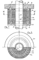
- Fig. 1 einen Längsschnitt durch eine erste Ausführungsform der Vorrichtung;
- Fig. 2 eine entlang der Linie 11-11 von Fig. 1 teilgeschnittene Stirnansicht der Vorrichtung gemäß Fig. 1;
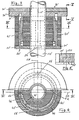
- Fig. 3 einen Längsschnitt durch eine zweite Ausführungsform der Vorrichtung;
- Fig. 4 eine entlang der Linie IV-IV von Fig. 3 teilgeschnittene Stirnansicht der zweiten Ausführungsform und
- Fig. 5 einen Schnitt entlang der Linie V-V von Fig. 3.
- 1 shows a longitudinal section through a first embodiment of the device.
- FIG. 2 shows an end view of the device according to FIG. 1, partially sectioned along line 11-11 of FIG. 1;
- 3 shows a longitudinal section through a second embodiment of the device;
- Fig. 4 is a partially sectioned end view of the second embodiment along the line IV-IV of Fig. 3 and
- 5 shows a section along the line VV of FIG. 3rd
Die erste Ausführungsform gemäß den Fig. 1 und 2 betrifft eine Vorrichtung, die während der Montage einer Rohrleitung 10 auf diese aufgeschoben und in den nicht dargestellten Durchbruch hineingedrückt wird. Die einzelnen Elemente der Vorrichtung brauchen bei dieser Art der Montage nicht geteilt zu sein.The first embodiment according to FIGS. 1 and 2 relates to a device which is pushed onto a
Die Vorrichtung weist zwei Spannelemente 20, 30 auf, von denen jedes aus einer ringförmigen Platte 21 bzw. 31 mit von dieser Platte ausgehendem Rohrabschnitt 22 bzw. 32 besteht. Fig. 1 weist aus, daß der Rand 23 der Platte 21 einen geringeren Durchmesser als der entsprechende Rand der anderen Platte 31 hat. Der resultierende radiale Überstand der anderen Platte 31 bildet eine Anlagefläche, bis zu der die Vorrichtung in den nicht dargestellten Durchbruch eingeschoben wird. Zum Durchführen der Rohrleitung 10 ist die Platte 21 mit einer Zentralbohrung 24 versehen. Die andere Platte 31 weist eine entsprechende Zentralbohrung 34 auf.The device has two
Der Rohrabschnitt 22 des Spannelementes 20 verläuft koaxial zur Achse 15 der Vorrichtung und ist ein integraler Bestandteil des Spannelementes. Er hat ausweislich der Zeichnung sowohl. einen Abstand vom Rand 23 als auch von der Zentralbohrung 24 und ist mit einem Innengewinde versehen.The
Der Rohrabschnitt 32 des Spannelementes 30 entspricht dem bereits geschilderten Rohrabschnitt 22. Sowohl sein Außen- als auch sein Innendurchmesser ist jedoch geringer als der jeweils entsprechende Durchmesser des Rohrabschnitts 22. Auf seinem Außenumfang ist der zum Spannelement 30 gehörige Rohrabschnitt 32 mit einem Außengewinde versehen, daß dem Innengewinde des anderen Rohrabschnitts 22 entspricht. Demgemäß lassen sich beide Rohrabschnitte miteinander verschrauben. Die Folge hiervon ist eine axiale Abstandsver- änderung der beiden Platten 21, 31.The
Die Vorrichtung ist mit einer zweiteiligen Dichtung ausgerüstet. Diese Dichtung wird von zwei koaxial zueinander angeordneten Hülsen 40, 42, Schläuchen o.dgl. gebildet, die üblicherweise aus Gummi bestehen.The device is equipped with a two-part seal. This seal is from two coaxially arranged
Die radial äußere der beiden Hülsen 40 liegt mit ihrer radial innen liegenden Fläche am Außenumfang des Rohrabschnitts 22 an und erstreckt sich in axialer Richtung zwischen dem außen liegenden Randbereich der Platte 21 sowie einem entsprechenden Abschnitt der anderen Platte 31. Der Außendurchmesser der Hülse 40 ist gleich oder etwas größer als der Durchmesser des Randes 23 der Platte 21.The radially outer surface of the two
Die radial innen liegende Hülse 42 stützt sich in radialer Richtung einerseits an der Rohrleitung 10 und andererseits an der Innenfläche des Rohrabschnitts 32 des Spannelementes 30 ab. Sie wird in axialer Richtung eingefaßt zwischen den innen liegenden Abschnitten der Platten 21, 31.The radially
Es sei an dieser Stelle angemerkt, daß sowohl die Platten 21, 31 als auch die innere Hülse 42 mehrere parallele Bohrungen analog zu den Bohrungen 24, 34 aufweisen können, wie es im Stand der Technik als solches bekannt ist, so daß mit einer Vorrichtung auch mehrere Rohrleitungen, Kabel o.dgl. gemeinsam abgedichtet werden können.It should be noted at this point that both the
Zur Montage der Vorrichtung in dem nicht dargestellten Durchbruch wird diese über die aus dem Durchbruch herausragende Rohrleitung 10 geschoben. Unmittelbar vor dem Einführen in den Durchbruch werden die beiden Spannelemente 20, 30 soweit gegeneinander verdreht, daß sich die äußere Hülse 40 geringfügig nach außen wölbt. Hierdurch soll erreicht werden, daß die äußere Hülse 40 beim Einschieben der Vorrichtung in den Durchbruch bereits unter einer leichten Vorspannung an der Wand des Durchbruchs oder Futterrohres anliegt. Nach dem vollständigen Einschieben der Vorrichtung in den Durchbruch wird die außerhalb des Durchbruchs verbleibende Platte 31 von Hand oder mittels eines Werkzeuges verdreht, so daß sich deren Rohrabschnitt 32 weiter in den anderen Rohrabschnitt 22 hineinschraubt. Die erwähnte Vorspannung zwischen äußerer Hülse 40 und Durchbruch bewirkt dabei, daß sich das innerhalb des Durchbruches befindliche Spannelement 20 nicht mitdreht. Es läßt sich somit eine Abdichtung von der einen Seite des Durchbruches her erreichen, so daß die Vorrichtung auch dort eingesetzt werden kann, wo die baulichen Verhältnisse die Zugänglichkeit zum Durchbruch nur von einer Seite gestattet.To assemble the device in the breakthrough, not shown, it is pushed over the
Die Betätigungsmöglichkeit der Vorrichtung, nur von einer Seite der Wand aus, setzt voraus, daß die Reibung zwischen äußerer Hülse 40 und Innenfläche des Durchbruchs sowie Außenfläche des Rohrabschnitts 22 so groß ist, daß das innen liegende Spannelement 20 durch das Verdrehen des äußeren Spannelementes 30 nicht mitgenommen wird. Es ist davon auszugehen, daß in der Praxis immer eine genügende Rauhigkeit auf der Seite des Durchbruches gegeben ist, die ein Mitdrehen der Hülse 40 verhindert. Entsprechend können auch die der Hülse 40 zugekehrten Oberflächen des Spannelementes 20 aufgerauht sein, während sich die Reibung zwischen den beiden Rohrabschnitten, zwischen der Hülse 40 und der äußeren Platte 31 sowie ggf. im Bereich der inneren Hülse 42 durch Zugabe eines Gleitmittels kleinhalten läßt.The possibility of actuation of the device, only from one side of the wall, presupposes that the friction between the
Die axiale Länge der beiden Rohrabschnitte 22, 32 muß so bemessen sein, daß sich die beiden Spannelemente 20, 30 um ein ausreichendes axiales Maß aufeinanderzu bewegen lassen. Andererseits können diese Rohrabschnitte nicht wesentlich kürzer sein als die axiale Länge der Hülsen, damit diese über ein ausreichendes Maß hinweg unterstützt bleiben. Fig. 1 zeigt am Beispiel der Platte 31 des Spannelementes 30, daß man ein ausreichendes Maß axialer Bewegbarkeit der beiden Spannelemente zueinander und gleichzeitig eine vollständige Unterstützung der Hülse 40 im festgespannten (nicht gezeichneten) Zustand dadurch erreicht, daß in der axialen Verlängerung des Rohrabschnittes 22 eine Ringnut 35 in der Platte 31 vorgesehen ist, in die sich der Rohrabschnitt 22 beim anziehen der Vorrichtung hineinbewegen kann. Eine entsprechende Ringnut kann im Bedarfsfall auch in der anderen Platte 21 vorgesehen werden.The axial length of the two
In den Fig. 3 bis 5 ist eine Abwandlung des bereits beschriebenen Ausführungsbeispiels dargestellt. Die Abwandlung besteht darin, daß die beiden Spannelemente 20', 30' jeweils zweiteilig ausgebildet sind und die beiden Hülsen 40', 42' vor der Montage aus flachem Material bestehen. Durch diese Ausbildung wird erreicht, daß sich die Vorrichtung unabhängig davon einsetzen läßt, ob die Rohrleitung 10 bereits fertig verlegt oder noch in der Montage begriffen ist. Die Bestandteile der Vorrichtung in der abgewandelten Ausführungsform lassen sich also auch noch nachträglich ihrem Zweck entsprechend einsetzen, wenn der Installateur oder Elektriker den Bau bereits wieder verlassen hat.3 to 5 a modification of the already described embodiment is shown. The modification is that the two clamping elements 20 ', 30' are each formed in two parts and the two
Ausweislich den Fig. 3 und 5 besteht die ringförmige Platte des Spannelementes 30' aus zwei etwa halbkreisförmigen Segmenten 31', 31", die entlang einer Mittellinie 50 mit zueinander komplementären Falzen versehen sind, wie insbesondere die Fig. 5 zeigt. Der Rohrabschnitt 32' des Spannelementes 30' ist sinngemäß in zwei Halbschalen geteilt, die im Bereich der Stoßstellen ebenfalls mit komplementären Falzen versehen sind, wie es in Fig. 4 bei 52 angedeutet ist. Das Spannelement 30' ist also zweiteilig und läßt sich dadurch um eine bereits verlegte Rohrleitung 10'zusammensetzen.3 and 5, the annular plate of the tensioning element 30 'consists of two approximately
In völlig analoger Weise ist auch das Spannelement 20' zweiteilig ausgebildet. Bei 54 sind die komplementären Falze der Segmente 21', 21" der zugehörigen Platte und bei 56 die Falze des zugehörigen Rohrabschnitts 22' erkenntlich (Fig. 3 bzw. 4). Des weiteren ist der Zeichnung zu entnehmen, daß die Lage der Falze des Spannelementes 30' (Linie 50) um etwa 90° gegenüber der Lage der Falze des Spannelementes 20' (Linie 58) verdreht ist.In a completely analogous manner, the tensioning element 20 'is also formed in two parts. The complementary folds of the
Die Hülsen 40' bzw. 42' dieser zweiten Ausführungsform werden - wie erwähnt - entweder als flache Zuschnitte geliefert, die an ihren Stirnflächen 44' bzw. 46' unmittelbar von der Montage zusammengeklebt werden, oder aber die am Bau an diesen Linien aufgeschnitten, um die Rohrleitung herumgelegt und dann wieder verklebt werden. Nach der Verklebung der Hülsen wird die äußere Hülse 40' über die aneinander liegenden Segmente 21', 21 des Spannelementes 20' geschoben und hält dessen Teile zusammen. Hieran anschließend wird die innere Hülse 42' in den Innenraum des Spannelementes 20' eingeschoben, worauf die beiden von Hand zusammengehaltenen Segmente 31', 31" mit den entsprechenden Schalen ihres Rohrabschnittes in das Spannelement 20' eingeschraubt werden können. Es versteht sich, daß sich beim Einschrauben die Lage der Linie 58 zur Lage der Linie 50 entsprechend der Drehbewegung ändert.The
Im übrigen entspricht die Vorrichtung des zweiten Ausführungsbeispiels derjenigen des ersten Ausführungsbeispiels.Otherwise, the device of the second embodiment corresponds to that of the first embodiment.
Claims (8)
Applications Claiming Priority (2)
| Application Number | Priority Date | Filing Date | Title |
|---|---|---|---|
| DE8512815U | 1985-05-02 | ||
| DE8512815U DE8512815U1 (en) | 1985-05-02 | 1985-05-02 | Device for sealing pipelines, cables or the like penetrated breakthroughs |
Publications (3)
| Publication Number | Publication Date |
|---|---|
| EP0200140A2 EP0200140A2 (en) | 1986-11-05 |
| EP0200140A3 EP0200140A3 (en) | 1987-05-06 |
| EP0200140B1 true EP0200140B1 (en) | 1989-04-05 |
Family
ID=6780546
Family Applications (1)
| Application Number | Title | Priority Date | Filing Date |
|---|---|---|---|
| EP86105526A Expired EP0200140B1 (en) | 1985-05-02 | 1986-04-22 | Device for sealing openings traversing conduits, cables or the like |
Country Status (2)
| Country | Link |
|---|---|
| EP (1) | EP0200140B1 (en) |
| DE (2) | DE8512815U1 (en) |
Families Citing this family (1)
| Publication number | Priority date | Publication date | Assignee | Title |
|---|---|---|---|---|
| CN104466839B (en) * | 2014-11-28 | 2018-02-23 | 国家电网公司 | Cable penetration protection device |
Family Cites Families (3)
| Publication number | Priority date | Publication date | Assignee | Title |
|---|---|---|---|---|
| DE1196447B (en) * | 1962-02-27 | 1965-07-08 | Gustav F J Schroeder | Sealing arrangement for wall ducts on pipes or cables |
| DE1204472B (en) * | 1962-10-09 | 1965-11-04 | Rheinisches Metallwerk Gmbh | Wall bushing for installation pipes with a radially tensionable press ring |
| DE3102710A1 (en) * | 1981-01-28 | 1982-08-12 | Erik Groesen 8800 Aarhus Jensen | Sealing device |
-
1985
- 1985-05-02 DE DE8512815U patent/DE8512815U1/en not_active Expired
-
1986
- 1986-04-22 DE DE8686105526T patent/DE3662721D1/en not_active Expired
- 1986-04-22 EP EP86105526A patent/EP0200140B1/en not_active Expired
Also Published As
| Publication number | Publication date |
|---|---|
| DE8512815U1 (en) | 1985-06-13 |
| DE3662721D1 (en) | 1989-05-11 |
| EP0200140A2 (en) | 1986-11-05 |
| EP0200140A3 (en) | 1987-05-06 |
Similar Documents
| Publication | Publication Date | Title |
|---|---|---|
| DE3216938C2 (en) | Pipe connection | |
| DE3631812C2 (en) | Pipe or hose connector | |
| EP0663047B1 (en) | Tube system for tubular constructions | |
| EP0039447A1 (en) | Screw-threaded cable fitting | |
| DE2948286A1 (en) | ALL-METAL CONNECTION | |
| DE2621044B2 (en) | Pipe connection | |
| DE2610878A1 (en) | PIPE CONNECTION WITH A SCREW SOCKET | |
| EP0100771B1 (en) | Tubbings for lining tunnels and shafts | |
| EP0200140B1 (en) | Device for sealing openings traversing conduits, cables or the like | |
| DE3102710C2 (en) | ||
| EP0905426A2 (en) | Sealing device for a lead-through for a line through a wall opening | |
| DE1958205A1 (en) | Shear protection for socket connections of pipes | |
| WO2002098628A2 (en) | Clamping ring for axially connecting cylindrical components | |
| EP0073050A1 (en) | Clamping connections for even circular bodies, especially pipes and rods | |
| DE102014114959B4 (en) | Pipe connecting device | |
| DE4009403C2 (en) | Pipe coupling | |
| DE3911258C2 (en) | ||
| EP0180656B1 (en) | Coupling for connecting pipes made of brittle materials | |
| EP0043593A1 (en) | Device for joining two flanges | |
| DE29901351U1 (en) | Adjustable wedge ring | |
| DE3536784C2 (en) | ||
| DE102006029242A1 (en) | Flange connection for connecting exhaust gas pipes, has flanges having respective angular surfaces that are provided at extensions so that angular surfaces point each other, where flanges are welded with corresponding pipe units | |
| DE9112027U1 (en) | Thin-walled pipe, especially sheathing pipe for tension members for anchors in the ground | |
| DE2929859A1 (en) | Shaft end joining equipment - has axial holders formed on clamping mechanism | |
| DE3707432C2 (en) |
Legal Events
| Date | Code | Title | Description |
|---|---|---|---|
| PUAI | Public reference made under article 153(3) epc to a published international application that has entered the european phase |
Free format text: ORIGINAL CODE: 0009012 |
|
| AK | Designated contracting states |
Kind code of ref document: A2 Designated state(s): CH DE LI NL |
|
| PUAB | Information related to the publication of an a document modified or deleted |
Free format text: ORIGINAL CODE: 0009199EPPU |
|
| RA1 | Application published (corrected) |
Date of ref document: 19861210 Kind code of ref document: A2 |
|
| PUAL | Search report despatched |
Free format text: ORIGINAL CODE: 0009013 |
|
| AK | Designated contracting states |
Kind code of ref document: A3 Designated state(s): CH DE LI NL |
|
| 17P | Request for examination filed |
Effective date: 19870812 |
|
| 17Q | First examination report despatched |
Effective date: 19871210 |
|
| GRAA | (expected) grant |
Free format text: ORIGINAL CODE: 0009210 |
|
| AK | Designated contracting states |
Kind code of ref document: B1 Designated state(s): CH DE LI NL |
|
| REF | Corresponds to: |
Ref document number: 3662721 Country of ref document: DE Date of ref document: 19890511 |
|
| PLBE | No opposition filed within time limit |
Free format text: ORIGINAL CODE: 0009261 |
|
| STAA | Information on the status of an ep patent application or granted ep patent |
Free format text: STATUS: NO OPPOSITION FILED WITHIN TIME LIMIT |
|
| 26N | No opposition filed | ||
| PGFP | Annual fee paid to national office [announced via postgrant information from national office to epo] |
Ref country code: NL Payment date: 19920430 Year of fee payment: 7 Ref country code: DE Payment date: 19920430 Year of fee payment: 7 |
|
| PGFP | Annual fee paid to national office [announced via postgrant information from national office to epo] |
Ref country code: CH Payment date: 19920518 Year of fee payment: 7 |
|
| PG25 | Lapsed in a contracting state [announced via postgrant information from national office to epo] |
Ref country code: LI Effective date: 19930430 Ref country code: CH Effective date: 19930430 |
|
| PG25 | Lapsed in a contracting state [announced via postgrant information from national office to epo] |
Ref country code: NL Effective date: 19931101 |
|
| NLV4 | Nl: lapsed or anulled due to non-payment of the annual fee | ||
| REG | Reference to a national code |
Ref country code: CH Ref legal event code: PL |
|
| PG25 | Lapsed in a contracting state [announced via postgrant information from national office to epo] |
Ref country code: DE Effective date: 19940101 |