EP0043593A1 - Device for joining two flanges - Google Patents
Device for joining two flanges Download PDFInfo
- Publication number
- EP0043593A1 EP0043593A1 EP81105330A EP81105330A EP0043593A1 EP 0043593 A1 EP0043593 A1 EP 0043593A1 EP 81105330 A EP81105330 A EP 81105330A EP 81105330 A EP81105330 A EP 81105330A EP 0043593 A1 EP0043593 A1 EP 0043593A1
- Authority
- EP
- European Patent Office
- Prior art keywords
- flanges
- clamping
- annular
- clamping members
- annular guide
- Prior art date
- Legal status (The legal status is an assumption and is not a legal conclusion. Google has not performed a legal analysis and makes no representation as to the accuracy of the status listed.)
- Granted
Links
Images

Classifications
-
- F—MECHANICAL ENGINEERING; LIGHTING; HEATING; WEAPONS; BLASTING
- F16—ENGINEERING ELEMENTS AND UNITS; GENERAL MEASURES FOR PRODUCING AND MAINTAINING EFFECTIVE FUNCTIONING OF MACHINES OR INSTALLATIONS; THERMAL INSULATION IN GENERAL
- F16L—PIPES; JOINTS OR FITTINGS FOR PIPES; SUPPORTS FOR PIPES, CABLES OR PROTECTIVE TUBING; MEANS FOR THERMAL INSULATION IN GENERAL
- F16L23/00—Flanged joints
- F16L23/04—Flanged joints the flanges being connected by members tensioned in the radial plane
- F16L23/08—Flanged joints the flanges being connected by members tensioned in the radial plane connection by tangentially arranged pin and nut
-
- F—MECHANICAL ENGINEERING; LIGHTING; HEATING; WEAPONS; BLASTING
- F16—ENGINEERING ELEMENTS AND UNITS; GENERAL MEASURES FOR PRODUCING AND MAINTAINING EFFECTIVE FUNCTIONING OF MACHINES OR INSTALLATIONS; THERMAL INSULATION IN GENERAL
- F16L—PIPES; JOINTS OR FITTINGS FOR PIPES; SUPPORTS FOR PIPES, CABLES OR PROTECTIVE TUBING; MEANS FOR THERMAL INSULATION IN GENERAL
- F16L23/00—Flanged joints
- F16L23/04—Flanged joints the flanges being connected by members tensioned in the radial plane
-
- F—MECHANICAL ENGINEERING; LIGHTING; HEATING; WEAPONS; BLASTING
- F16—ENGINEERING ELEMENTS AND UNITS; GENERAL MEASURES FOR PRODUCING AND MAINTAINING EFFECTIVE FUNCTIONING OF MACHINES OR INSTALLATIONS; THERMAL INSULATION IN GENERAL
- F16L—PIPES; JOINTS OR FITTINGS FOR PIPES; SUPPORTS FOR PIPES, CABLES OR PROTECTIVE TUBING; MEANS FOR THERMAL INSULATION IN GENERAL
- F16L23/00—Flanged joints
- F16L23/16—Flanged joints characterised by the sealing means
- F16L23/18—Flanged joints characterised by the sealing means the sealing means being rings
- F16L23/20—Flanged joints characterised by the sealing means the sealing means being rings made exclusively of metal
Definitions
- the present invention relates to a device for connecting two flanges with a clamping device which serves to axially compress the flanges and surround the flanges and which comprises a plurality of clamping members distributed over the circumference of the flanges, each of which has an indentation facing the flanges, through the side walls of which the flanges a contraction of the clamping device and a resultant, radially inward movement of the clamping members are axially compressed, and which are connected to a relatively shear-resistant connecting device; furthermore with a tensioning device for pulling the ends of the clamping device together; and with an annular guide receiving the clamping device for centering the clamping device when the clamping device is released.
- a device of this type is known from US-A-26 40 717, Fig. 8-12.
- the clamping device of this known device is a so-called tension roller chain, which has a certain shear rigidity due to special extended connecting plates.
- a device for connecting two flanges is known, the clamping device of which consists of a spring arrangement surrounding the flanges, e.g. a leaf spring to which a number of terminal blocks are attached.
- the terminal blocks can be moved along the spring arrangement and are held on it by friction.
- the invention avoids these disadvantages in that in the case of a device of the type specified in the introduction, one end of the clamping device is fixed in the circumferential direction of the annular guide and in that the relatively shear-resistant connection arrangement consists, in a manner known per se, of an annular spring arrangement on which the clamping members in the circumferential direction are slidably attached.
- the device according to the invention enables proper spreading and opening of the clamping device, so that the flanges are released safely.
- the clamping device cannot buckle inwards in any assembly position and prevent the flanges from moving apart or moving together. Because one end of the clamping device is fixed in the circumferential direction, the device according to the invention is particularly well suited for remote control, e.g. by manipulators or servo motors.
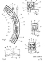
- the flange connection device shown in FIGS. 1 to 4 contains a clamping device with a tension roller chain 10, which contains a series of tension rollers 12 and chain links in the form of plates 14.
- the tensioning rollers 10 have a spool-like shape (see FIG. 2) and are provided with bearing bolts 16 which are connected to one another in an articulated manner on both sides via the tabs 14.
- the tension roller chain 10 is accommodated in an annular guide in the form of a chain case 18 which has a substantially U-shaped cross section and is open towards the inside (FIG. 2).
- a spring element in the form of a leaf spring 20 is arranged on the radially outer side of the tension roller chain 10.
- the leaf spring 20 is coupled to the links 14 of the chain links via U-shaped brackets in such a way that, on the one hand, the tensioning roller chain is prevented from buckling when its ends are spread apart, and on the other hand, the tensioning roller chain is tensioned around the circumference of two flanges 24, 26 (FIG. 2) to be connected can be.
- the tensioning roller chain is tensioned and opened by means of a tensioning device which contains a tensioning screw 28 which, on the one hand, is rotatably supported in a bearing block 30, which is formed by the central part of a tensioning roller 12 'at one end of the tensioning roller chain 10, and axially by a snap ring 32 is secured.
- the tensioning screw 28 is screwed with a threaded part 28a into a thread block 34, which is formed by the middle part of a tensioning roller 12 "at the other end of the tensioning roller chain.
- the clamping screw 28 extends through two holes 36 and 38 in the peripheral wall of the chain case 18 to the outside.
- the holes are dimensioned so that the tension screw 28 can pivot when opening or closing in accordance with the change in the diameter of the tension roller chain.
- the leaf spring 20 is loosely inserted into the brackets 22 riveted to the tabs 14, preferably with the exception of a bracket 22 to which the leaf spring is attached, to fix their middle position in relation to the tension roller chain.
- the attachment is preferably carried out on a bracket which is not visible in FIG. 1 and is diametrically opposite the free ends of the leaf spring.
- the leaf spring 20 thus tries to keep the diameter of the tension roller chain as large as possible.
- the leaf spring 20 is provided near its ends in FIG. 1 with longitudinal slots through which the clamping screw 28 extends.
- the bearing pin 16 '(FIGS. 3 and 4) is the clamping which forms the bearing block 30 roll 12 'extended on both sides and guided in radial slots 40 of the side walls of the chain case 18, as shown in FIGS. 3 and 4.
- One flange 24 can be connected to the chain case 18, as shown in FIG. 2.
- the other, movable flange 26 is advantageously connected to a centering disk 42 which has a series of axial holes 44 which cooperate with guide bolts 46 which are attached to the side wall of the chain case 18 facing away from the stationary flange 24.
- the centering disk together with the tapered guide bolts 46, ensures perfect centering of the flanges 24 and 26 to be connected.
- Fig. 5 shows another advantageous centering device for the movable flange. Centering takes place here through a conical surface 46 'which is inclined to the flange axis and which, for is formed by turning on the chain case 18 ', and by a conical recess 44' of a centering disk 42 'connected to the movable flange.
- the centering disk 42 'thus forms an annular depression which widens somewhat towards the open side and is complementary to the side of the chain case which faces it and which contains the inclined surface 46'.
- Both the surface 46 'and the surface 44' can, as shown, consist of two areas of different cone angles in order to facilitate centering.
- the tension roller chain 10 When the ends of the tension roller chain 10 are separated from one another by the tension screw 28, the tension roller chain opens uniformly and finally lies with the brackets 22 along their entire length on the outer wall of the chain case 18. The position of the tension roller chain is then precisely fixed and all tension rollers 12 are removed from the flanges 24 and 26, so that the flange 26 can be withdrawn unhindered. The same applies to the insertion of the flange 26 into the open clamping device.
- the flanges 24 and 26 which are expediently provided with bevelled side surfaces, are firmly clamped together.
- 1 to 5 can be constructed for the flanges of any nominal diameter, special advantages arise with large nominal diameters, e.g. 400 mm and more. It is particularly well suited for operation by remote control devices such as manipulators or servomotors. It can be used for both pressure-resistant and vacuum-tight connections.
- the tension chain can also be made of antimagnetic materials, such as brass and / or non-magnetic stainless steel, and can also generate a tension force in such a design that is suitable for sealing both high-vacuum and pressure connections for a medium pressure range of e.g. is suitable up to 10 bar.
- antimagnetic materials such as brass and / or non-magnetic stainless steel
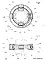
- the flange connection device 110 shown in FIGS. 6 and 7 is used to connect two pipe flanges 112, 114, the flanks of which face away from one another, as shown in broken lines in FIG. 7.
- This embodiment is particularly simple and inexpensive to manufacture. It is particularly suitable for flange connections with nominal widths below 100 mm.
- clamping blocks or clamping blocks 116, 118, 120 and 122 each of which has a groove-like indentation with oblique sides on the side facing the flanges have walls.
- the slope of the side walls of the indentation is preferably equal to the slope of the outer flanks of the flanges 112, 114, as can be seen in FIG. 7.
- the clamping blocks 116, 118, 120 and 122 are guided in radial guide grooves 126 (FIG. 2), which are formed in the side walls of an annular guide in the form of a support ring 128 which is U-shaped in cross section and is open towards the inside.
- the clamping blocks 116, 118 and 120 each have a slot-shaped recess 130 on their side facing away from the flanges, which runs in the circumferential direction of the flanges and has an elongated cross section in the axial direction of the flanges.
- the recesses 130 preferably have an approximately T-shaped cross section and are open to the outside, as shown in FIG. 7.
- the recesses 130 receive a tensioning strap 132, which is provided with a tensioning device 134.
- a type of hose clamp with tensioning screw 136 which is rotatably mounted in a holder 138, is preferably used as the tensioning strap with tensioning device.
- the holder and one end of the tensioning strap are fastened to the clamping block 122, the other end 132a of the tensioning strap is provided with a rack-like embossing in which the worm 136 engages.
- the tensioning band is contracted or expanded depending on the direction of rotation, in which case the clamping blocks are pressed against the flanges 112, 114 and compress them axially or the clamping blocks are removed from the flanges and release them.
- the screw is shown schematically in FIG. 7 with a slot 142 for a screwdriver and the like. In practice, it can be provided with a coupling member for a flexible shaft or another drive element.
- the outer wall 128c of the retaining ring 128, which serves to center the clamping blocks 116, 118, 120, 122 when the tensioning device is open, has a cutout 128a through which the worm 136 is accessible.
- the retaining ring 128 with its outer wall 128c is a suitable limit for opening the clamping blocks 116, 118, 120 and 122, so that they are concentric with the retaining ring 128.
- the retaining ring 128 is provided with an inner wall 128b which has cutouts at the location of the clamping blocks 116, 118, 120 and 122 through which the clamping blocks are passed.
- the inner wall 128b then also forms a support for the tensioning strap 132 in the pieces lying between the clamping blocks.
- terminal blocks can also be provided if necessary.
- the sealing arrangement shown in FIG. 8, which is particularly suitable for remote-controlled systems, is preferably used to seal the flanges.
- the flanges 112, 114 each have in their end faces an annular groove 150 with cylindrical jacket-shaped side walls and a base area 154 running perpendicular to the flange axis 152.
- a hollow cylindrical sealing ring 156 which in the white considerably has the shape of a straight hollow cylinder and is dimensioned such that it fits into the annular grooves 150 aligned with one another in the assembled state of the flange connection.
- the axial ends of the sealing ring 156 taper in a wedge shape and each form a sharp end edge.
- the flanges 112, 114 are expediently made of a relatively hard material, such as steel, while the sealing ring 150 is made of a material, such as pure aluminum, an aluminum alloy, copper or the like, which is relatively easily deformable in comparison with the flange material, so that it is deform the tapered axial ends of the sealing ring when the flanges are pressed together and results in a perfect seal between the sealing ring and the groove base.
- the groove in at least one of the flanges is advantageously at least so deep that a sufficiently secure fit of the sealing ring in the groove in question is ensured when the sealing ring is inserted into the groove.
- This has the advantage that the flange connection can be easily manipulated without the sealing ring falling out. You can also insert the sealing ring into the groove of one flange and later the flange connection e.g. assemble by an automatic device or a remote-controlled device, in which case the wedge-shaped ends of the sealing ring and its hollow cylindrical middle part bring about an automatic centering of the two flanges.
Abstract
Description
Die vorliegende Erfindung betrifft eine Einrichtung zum Verbinden zweier Flansche mit einer zum axialen Zusammenpressen der Flansche dienenden, die Flansche umgebenden Klemmvorrichtung, die mehrere, auf den Umfang der Flansche verteilte Klemmglieder enthält, welche jeweils eine den Flanschen zugewandte Einbuchtung aufweisen, durch deren Seitenwände die Flansche einem Zusammenziehen der Klemmvorrichtung und einer dadurch bewirkten, radial nach innen gerichteten Bewegung der Klemmglieder axial zusammengepreßt werden, und welche mit einer relativ schubsteifen Verbindungsvorrichtung verbunden sind; ferner mit einer Spannvorrichtung, zum Zusammenziehen der Enden der Klemmvorrichtung; und mit einer die Klemmvorrichtung aufnehmenden ringförmigen Führung zum Zentrieren der Klemmvorrichtung beim Lösen der Spannvorrichtung.The present invention relates to a device for connecting two flanges with a clamping device which serves to axially compress the flanges and surround the flanges and which comprises a plurality of clamping members distributed over the circumference of the flanges, each of which has an indentation facing the flanges, through the side walls of which the flanges a contraction of the clamping device and a resultant, radially inward movement of the clamping members are axially compressed, and which are connected to a relatively shear-resistant connecting device; furthermore with a tensioning device for pulling the ends of the clamping device together; and with an annular guide receiving the clamping device for centering the clamping device when the clamping device is released.
Eine Einrichtung dieser Art ist aus US-A-26 40 717, Fig. 8 - 12, bekannt. Die Klemmvorrichtung dieser bekannten Einrichtung ist eine sogenannte Spannrollenkette, die durch spezielle verlängerte Verbindungslaschen eine gewisse Schubsteifigkeit aufweist.A device of this type is known from US-A-26 40 717, Fig. 8-12. The clamping device of this known device is a so-called tension roller chain, which has a certain shear rigidity due to special extended connecting plates.
Aus der GB-A-886 036 ist eine Einrichtung zum Verbinden zweier Flansche bekannt, deren Klemmvorrichtung aus einer die Flansche umgebenden Federanordnung, z.B. einer Blattfeder, an der eine Anzahl von Klemmblöcken angebracht sind. Die Klemmblöcke sind längs der Federanordnung verschiebbar und an ihr durch Reibungsschluß gehaltert.From GB-A-886 036 a device for connecting two flanges is known, the clamping device of which consists of a spring arrangement surrounding the flanges, e.g. a leaf spring to which a number of terminal blocks are attached. The terminal blocks can be moved along the spring arrangement and are held on it by friction.
Eine ähnliche Einrichtung, bei der die Klemmblöcke jedoch durch Schrauben an einer Blattfeder fixiert sind, ist aus DE-C-937 264 bekannt.A similar device, in which the terminal blocks are fixed to a leaf spring by screws, is known from DE-C-937 264.
Bei den bekannten Einrichtungen ist nicht mit Sicherheit gewährleistet, daß die Flansche beim Lösen der Spannvorrichtung von der Klemmvorrichtung völlig freigegeben werden. Außerdem eignen sie sich schlecht für eine ferngesteuerte Betätigung.In the known devices it is not guaranteed with certainty that the flanges are completely released from the clamping device when the clamping device is released. In addition, they are poorly suited for remote operation.
Die Erfindung vermeidet diese Nachteile dadurch, daß bei einer Einrichtung der eingangs angegebenen Art das eine Ende der Klemmvorrichtung in Umfangsrichtung der ringförmigen Führung fixiert ist und daß die relativ schubsteife Verbindungsanordnung in an sich bekannter Weise aus einer ringförmigen Federanordnung besteht, an der die Klemmglieder in Umfangsrichtung verschiebbar angebracht sind.The invention avoids these disadvantages in that in the case of a device of the type specified in the introduction, one end of the clamping device is fixed in the circumferential direction of the annular guide and in that the relatively shear-resistant connection arrangement consists, in a manner known per se, of an annular spring arrangement on which the clamping members in the circumferential direction are slidably attached.
Die Einrichtung gemäß der Erfindung ermöglicht ein einwandfreies Spreizen und öffnen der Klemmvorrichtung, so daß die Flansche sicher freigegeben werden. Die Klemmvorrichtung kann in keiner Montageposition nach innen einknicken und das Auseinanderfahren oder Zusammenfahren der Flansche verhindern. Dadurch, daß das eine Ende der Klemmvorrichtung in Umfangsrichtung fixiert ist, eignet sich die Einrichtung gemäß der Erfindung besonders gut für eine Fernbedienung, z.B. durch Manipulatoren oder Servomotoren.The device according to the invention enables proper spreading and opening of the clamping device, so that the flanges are released safely. The clamping device cannot buckle inwards in any assembly position and prevent the flanges from moving apart or moving together. Because one end of the clamping device is fixed in the circumferential direction, the device according to the invention is particularly well suited for remote control, e.g. by manipulators or servo motors.
Im folgenden werden Ausführungsbeispiele der Erfindung unter Bezugnahme auf die Zeichnungen näher erläutert.Exemplary embodiments of the invention are explained in more detail below with reference to the drawings.
Es zeigen:
- Fig. 1 eine axiale Draufsicht auf eine bevorzugte Ausführungsform der Einrichtung gemäß der Erfindung, wobei eine dem Betrachter zugewandte Seitenwand eines Kettenkastens weggeschnitten und Teile des Inneren der Vorrichtung weggebrochen sind;
- Fig. 2 einen Radialschnitt der Einrichtung gemäß Fig. 1 mit zwei Flanschen im geschlossenen Zustand der Einrichtung;
- Fig. 3 eine axiale Draufsicht auf einen Teil des Kettenkastens der Einrichtung gemäß Fig. 1 und 2;
- Fig. 4 ein Radialschnitt in einer Ebene IV-IV der Fig. 3;
- Fig. 5 eine Fig. 2 entsprechende Darstellung mit einer anderen vorteilhaften Zentriervorrichtung;
- Fig. 6 eine axiale, teilweise geschnittene Ansicht einer Einrichtung gemäß einer zweiten Ausführungsform der Erfindung;
- Fig. 7 eine Seitenansicht der Einrichtung gemäß Fig. 6 im Axialschnitt;
- Fig. 8 eine Schnittansicht einer Abdichtanordnung, wie sie vorteilhafterweise in Kombination mit einer Einrichtung gemäß der Erfindung verwendet wird.
- Figure 1 is an axial plan view of a preferred embodiment of the device according to the invention, wherein a side wall of a chain case facing the viewer is cut away and parts of the interior of the device are broken away.
- FIG. 2 shows a radial section of the device according to FIG. 1 with two flanges in the closed state of the device;
- 3 shows an axial plan view of part of the chain case of the device according to FIGS. 1 and 2;
- Fig. 4 is a radial section in a plane IV-IV of Fig. 3;
- FIG. 5 shows a representation corresponding to FIG. 2 with another advantageous centering device;
- Fig. 6 is an axial, partially sectioned view of a device according to a second embodiment the invention;
- FIG. 7 shows a side view of the device according to FIG. 6 in axial section;
- Fig. 8 is a sectional view of a sealing arrangement as it is advantageously used in combination with a device according to the invention.
Die in den Fig. 1 bis 4 dargestellte Flanschverbindungseinrichtung enthält eine Klemmvorrichtung mit einer Spannrollenkette 10, die eine Reihe von Spannrollen 12 und Kettenglieder in Form von Laschen 14 enthält. Die Spannrollen 10 haben eine garnspulenartige Form (siehe Fig. 2) und sind mit Lagerbolzen 16 versehen, die auf beiden Seiten über die Laschen 14 gelenkig miteinander verbunden sind.The flange connection device shown in FIGS. 1 to 4 contains a clamping device with a
Die Spannrollenkette 10 ist in einer ringförmigen Führung in Form eines Kettenkastens 18 untergebracht, der einen im wesentlichen U-förmigen Querschnitt hat und nach innen offen ist (Fig. 2). Auf der radial äußeren Seite der Spannrollenkette 10 ist ein Federelement in Form einer Blattfeder 20 angeordnet. Die Blattfeder 20 ist mit den Laschen 14 der Kettenglieder über U-förmige Bügel so gekoppelt, daß einerseits ein Einknicken der Spannrollenkette beim Auseinanderspreizen ihrer Enden verhindert wird, die Spannrollenkette andererseits um den Umfang zweier zu verbindender Flansche 24, 26 (Fig. 2) gespannt werden kann.The
Das Zusammenspannen und Öffnen der Spannrollenkette erfolgt mittels einer Spannvorrichtung, die eine Spannschraube 28 enthält, welche einerseits in einem Lagerblock 30, der durch den mittleren Teil einer Spannrolle 12' am einen Ende der Spannrollenkette 10 gebildet wird, drehbar gelagert und durch einen Sprengring 32 axial gesichert ist. Andererseits ist die Spannschraube 28 mit einem Gewindeteil 28a in einen Gewindeblock 34 eingeschraubt, der durch den mittleren Teil einer Spannrolle 12" am anderen Ende der Spannrollenkette gebildet wird. Durch Drehen der Spannschraube 28 können also die Enden der Spannrollenkette zusammengespannt oder auseinandergespreizt werden, wobei sich der Durchmesser der Spannrollenkette verkleinert bzw. vergrößert. Die zusammengespannte Stellung, in der die Spannrollenkette ihren kleineren Durchmesser hat, ist in Fig. 1 mit ausgezogenen Linien und in Fig. 2 dargestellt; die auseinandergespreizte, geöffnete Stellung der Spannrollenkette ist in Fig. 1 gestrichelt dargestellt.The tensioning roller chain is tensioned and opened by means of a tensioning device which contains a
Die Spannschraube 28 erstreckt sich durch zwei Löcher 36 und 38 in der Umfangswand des Kettenkastens 18 nach außen. Die Löcher sind so bemessen, daß die Spannschraube 28 entsprechend der Änderung des Durchmessers der Spannrollenkette beim öffnen bzw. Schließen schwenken kann.The
Damit die Durchmesseränderungen der Spannrollenkette 10 beim Öffnen bzw. Schließen der Flanschverbindungsvorrichtung durch die Blattfeder 20 nicht behindert wird, ist letztere lose in die an den Laschen 14 angenieteten Bügel 22 eingelegt, vorzugsweise mit Ausnahme von einem Bügel 22, an dem die Blattfeder befestigt ist, um ihre mittlere Lage bezüglich der Spannrollenkette zu fixieren. Vorzugsweise erfolgt die Befestigung an einem in Fig. 1 nicht sichtbaren Bügel, der den freien Enden der Blattfeder diametral gegenüber liegt. Die Blattfeder 20 stebt also dazu, den Durchmesser der Spannrollenkette möglichst groß zu halten. Die Blattfeder 20 ist in der Nähe ihrer in Fig. 1 sichtbaren Enden mit Längsschlitzen versehen, durch die sich die Spannschraube 28 erstreckt. Zur Fixierung der Lage der Spannschraube 28 bezüglich des Kettenkastens 18 ist der Lagerbolzen 16' (Fig. 3 und 4) der den Lagerblock 30 bildenden Spannrolle 12' beidseits verlängert und in radialen Schlitzen 40 der Seitenwände des Kettenkastens 18 geführt, wie in Fig. 3 und 4 dargestellt ist.So that the diameter changes of the
Der eine Flansch 24 kann mit dem Kettenkasten 18 verbunden sein, wie es in Fig. 2 dargestellt ist. Der andere, bewegliche Flansch 26 ist vorteilhafterweise mit einer Zentrierscheibe 42 verbunden, welche eine Reihe von axialen Löchern 44 aufweist, welche mit Führungsbolzen 46 zusammenwirken, die an der dem stationären Flansch 24 abgewandten Seitenwand des Kettenkastens 18 angebracht sind. Die Zentrierscheibe gewährleistet zusammen mit den spitz zulaufenden Führungsbolzen 46 eine einwandfreie Zentrierung der zu verbindenden Flansche 24 und 26.One
Fig. 5 zeigt eine andere, vorteilhafte Zentriervorrichtung für den beweglichen Flansch. Die Zentrierung erfolgt hier durch eine zur Flanschachse schräge, konische Fläche 46', die z.B. durch Andrehen des Kettenkastens 18' gebildet ist, und durch eine konische Ausdrehung 44' einer mit dem beweglichen Flansch verbundenen Zentrierscheibe 42'. Die Zentrierscheibe 42' bildet also eine ringförmige, sich zur offenen Seite hin etwas erweiternde Vertiefung, die komplementär zu der ihr zugewandten, die schräge Fläche 46' enthaltenden Seite des Kettenkastens geformt ist. Sowohl die Fläche 46' als auch die Fläche 44' können, wie dargestellt, aus zwei Bereichen unterschiedlichen Kegelwinkels bestehen, um die Zentrierung zu erleichtern.Fig. 5 shows another advantageous centering device for the movable flange. Centering takes place here through a conical surface 46 'which is inclined to the flange axis and which, for is formed by turning on the chain case 18 ', and by a conical recess 44' of a centering disk 42 'connected to the movable flange. The centering disk 42 'thus forms an annular depression which widens somewhat towards the open side and is complementary to the side of the chain case which faces it and which contains the inclined surface 46'. Both the surface 46 'and the surface 44' can, as shown, consist of two areas of different cone angles in order to facilitate centering.
Wenn die Enden der Spannrollenkette 10 durch die Spannschraube 28 voneinander entfernt werden, öffnet sich die Spannrollenkette gleichmäßig und legt sich schließlich mit den Bügeln 22 längs ihrer ganzen Länge an der Außenwand des Kettenkastens 18 an. Die Lage der Spannrollenkette ist dann genau fixiert und alle Spannrollen 12 sind von den Flanschen 24 und 26 entfernt, so daß der Flansch 26 unbehindert zurückgezogen werden kann. Entsprechendes gilt für das Einfahren des Flansches 26 in die geöffnete Spannvorrichtung. Beim Zusammenziehen der Enden der Spannrollenkette durch die Spannschraube 28 werden die zweckmäßigerweise mit abgeschrägten Seitenflächen versehenen Flansche 24 und 26 fest zusammengespannt.When the ends of the
Die Flanschverbindungseinrichtung gemäß Fig. 1 bis 5 kann für die Flansche beliebigen Nenndurchmessers konstruiert werden, besondere Vorteile ergeben sich bei großen Nenndurchmessern, z.B. 400 mm und mehr. Sie eignet sich besonders gut für eine Betätigung durch Fernbedienungseinrichtungen wie Manipulatoren oder Servomotoren. Sie kann sowohl für druckfeste als auch für vakuumdichte Verbindungen verwendet werden.1 to 5 can be constructed for the flanges of any nominal diameter, special advantages arise with large nominal diameters, e.g. 400 mm and more. It is particularly well suited for operation by remote control devices such as manipulators or servomotors. It can be used for both pressure-resistant and vacuum-tight connections.
Die Spannkette kann auch aus antimagnetischen Werkstoffen gefertigt werden, wie Messing und/oder unmagnetischem nichtrostendem Stahl, und vermag auch in einer solchen Ausführung eine Spannkraft zu erzeugen, die für eine Abdichtung sowohl von Hochvakuum- als auch Druckverbindungen für einen mittleren Druckbereich von z.B. bis 10 bar geeignet ist.The tension chain can also be made of antimagnetic materials, such as brass and / or non-magnetic stainless steel, and can also generate a tension force in such a design that is suitable for sealing both high-vacuum and pressure connections for a medium pressure range of e.g. is suitable up to 10 bar.
Die in Fig. 6 und 7 dargestellte Flanschverbindungseinrichtung 110 dient zum Verbinden zweier Rohrflansche 112, 114, deren einander abgewandte Flanken konisch ausgebildet sind, wie in Fig. 7 gestrichelt dargestellt ist. Diese Ausführungsform ist besonders einfach und preiswert in der Herstellung. Sie eignet sich besonders für Flanschverbindungen mit Nennweiten unter 100 mm.The
Die Flanschverbindungseinrichtung gemäß Fig. 6 und 7 enthält vier Klemmsteine oder Spannblöcke 116,118,120 und 122, die an der den Flanschen zugewandten Seite jeweils eine nutartige Einbuchtung mit schrägen Seitenwänden aufweisen. Die Schräge der Seitenwände der Einbuchtung ist vorzugsweise gleich der Schräge der äußeren Flanken der Flansche 112, 114, wie aus Fig. 7 ersichtlich ist. Die Spannblöcke 116, 118, 120 und 122 sind in radialen Führungsnuten 126 (Fig. 2) geführt, die in den Seitenwänden einer ringförmigen Führung in Form eines im Querschnitt U-förmigen, nach innen hin offenen Halterungsringes 128 gebildet sind.6 and 7 contains four clamping blocks or
Die Klemmblöcke 116, 118 und 120 weisen auf ihrer den Flanschen abgewandeten Seite jeweils eine schlitzförmige Ausnehmung 130 auf, die in Umfangsrichtung der Flansche verläuft und einen in Achsrichtung der Flansche langgestreckten Querschnitt hat. Die Ausnehmungen 130 haben vorzugsweise einen etwa T-förmigen Querschnitt und sind nach außen offen, wie es in Fig. 7 dargestellt ist.The clamping blocks 116, 118 and 120 each have a slot-shaped
Die Ausnehmungen 130 nehmen ein Spannband 132 auf, das mit einer Spannvorrichtung 134 versehen ist. Als Spannband mit Spannvorrichtung wird vorzugsweise eine Art von Schlauchklemmbride mit Spannschnecke 136 verwendet, welche in einer Halterung 138 drehbar gelagert ist. Die Halterung und das eine Ende des Spannbandes sind am Klemmblock 122 befestigt, das andere Ende 132a des Spannbandes ist mit einer zahnstangenartigen Prägung versehen, in die die Schnecke 136 eingreift. Beim Drehen der Schnekke wird das Spannband je nach Drehrichtung zusammengezogen oder erweitert, wobei dann die Klemmblöcke gegen die Flansche 112, 114 gedrückt werden und diese axial zusammenpressen bzw. die Klemmblöcke von den Flanschen entfernt werden und diese freigeben. Die Schnecke ist in Fig. 7 schematisch mit einem Schlitz 142 für einen Schraubendreher und dgl. dargestellt, sie kann in der Praxis mit einem Kupplungsglied für eine biegsamme Welle oder ein anderes Antriebselement versehen sein.The
Die Außenwand 128c des Halterungsringes 128, die zur Zentrierung der Klemmblöcke 116, 118, 120, 122 im geöffneten Zustand der Spannvorrichtung dient, weist einen Ausschnitt 128a auf, durch den die Schnecke 136 zugänglich ist.The
Der Halterungsring 128 ist mit seiner Außenwand 128c eine zum öffnen der Klemmblöcke 116, 118, 120 und 122 geeignete Begrenzung, so daß diese konzentrisch zum Halterungsring 128 stehen.The retaining
Der Halterungsring 128 ist mit einer Innenwand 128b versehen, die am Ort der Klemmblöcke 116, 118, 120 und 122 Ausschnitte aufweist, durch die die Klemmblöcke hindurchgeführt werden. Die Innenwand 128b bildet dann gleichzeitig auch eine Auflage für das Spannband 132 in den zwischen den Klemmblöcken liegenden Stücken.The retaining
Selbstverständlich können im Bedarfsfall auch weniger oder mehr als vier Klemmblöcke vorgesehen sein.Of course, fewer or more than four terminal blocks can also be provided if necessary.
Bei nicht zugänglichen, z.B. radioaktiv verseuchten Anlagen wird es im allgemeinen, wie bei den Ausführungsbeispielen gemäß Fig. 1 bis 4, zweckmäßig sein, den Halterungsring bezüglich des einen Flansches zu fixieren. Man kann dann z.B. eine Apparatur, die mit dem einen Flansch und mit der Verbindungseinrichtung versehen ist, einfach mit einem Kran oder dgl. manipulieren.In the case of inaccessible, e.g. radioactive contaminated systems, it will generally be expedient, as in the exemplary embodiments according to FIGS. 1 to 4, to fix the mounting ring with respect to the one flange. You can then e.g. manipulate an apparatus which is provided with a flange and with the connecting device, simply with a crane or the like.
Zur Abdichtung der Flansche wird vorzugsweise die in Fig. 8 dargestellte Abdichtanordnung verwendet, die sich besonders gut für fernbediente Anlagen eignet.The sealing arrangement shown in FIG. 8, which is particularly suitable for remote-controlled systems, is preferably used to seal the flanges.
Die Flansche 112, 114 weisen in ihren Stirnflächen jeweils eine ringförmige Nut 150 mit zylindermantelförmigen Seitenwänden und einer senkrecht zur Flanschachse 152 verlaufenden Grundfläche 154 auf. In den Nuten 150 sitzt ein hohlzylinderförmiger Dichtring 156, der im wesentlichen die Form eines geraden Hohlzylinders hat und so bemessen ist, daß er in die im montierten Zustand der Flanschverbindung miteinander fluchtenden Ringnuten 150 paßt. Die axialen Enden des Dichtringes 156 verjüngen sich keilförmig und bilden jeweils eine scharfe stirnseitige Kante.The
Die Flansche 112, 114 bestehen zweckmäßigerweise aus einem verhältnismäßig harten Werkstoff, wie Stahl, während der Dichtring 150 aus einem Werkstoff, wie Reinaluminium, einer Aluminiumlegierung, Kupfer oder dgl. gefertigt wird, der im Vergleich zum Flanschwerkstoff verhältnismäßig leicht deformierbar ist, so daß sich die spitz zulaufenden axialen Enden des Dichtringes beim Zusammenpressen der Flansche verformen und eine einwandfreie Dichtung zwischen dem Dichtring und der Nutengrundfläche ergibt.The
Die Nut in mindestens einem der Flansche ist vorteilhafterweise mindestens so tief, daß ein genügend sicherer Sitz des Dichtringes in der betreffenden Nut gewährleistet ist, wenn der Dichtring in die Nut eingesetzt ist. Dies hat den Vorteil, daß die Flanschverbindung leicht manipuliert werden kann, ohne daß der Dichtring herausfällt. Man kann ferner den Dichtring in die Nut des einen Flansches einsetzen und später die Flanschverbindung z.B. durch eine automatische Vorrichtung oder ein fernbedientes Gerät montieren, wobei dann die keilförmig zulaufenden Enden des Dichtringes und dessen hohlzylinderförmiger mittlerer Teil eine automatische Zentrierung der beiden Flansche bewirken.The groove in at least one of the flanges is advantageously at least so deep that a sufficiently secure fit of the sealing ring in the groove in question is ensured when the sealing ring is inserted into the groove. This has the advantage that the flange connection can be easily manipulated without the sealing ring falling out. You can also insert the sealing ring into the groove of one flange and later the flange connection e.g. assemble by an automatic device or a remote-controlled device, in which case the wedge-shaped ends of the sealing ring and its hollow cylindrical middle part bring about an automatic centering of the two flanges.
Claims (13)
Applications Claiming Priority (4)
| Application Number | Priority Date | Filing Date | Title |
|---|---|---|---|
| DE19803026060 DE3026060A1 (en) | 1980-07-09 | 1980-07-09 | Remote operated flanged joint locking mechanism - uses roller chain carrying tensioning screw and supported inside circular leaf spring inside housing |
| DE3026060 | 1980-07-09 | ||
| DE19813111997 DE3111997A1 (en) | 1981-03-26 | 1981-03-26 | Flange connection device |
| DE3111997 | 1981-03-26 |
Publications (2)
| Publication Number | Publication Date |
|---|---|
| EP0043593A1 true EP0043593A1 (en) | 1982-01-13 |
| EP0043593B1 EP0043593B1 (en) | 1985-03-27 |
Family
ID=25786540
Family Applications (1)
| Application Number | Title | Priority Date | Filing Date |
|---|---|---|---|
| EP81105330A Expired EP0043593B1 (en) | 1980-07-09 | 1981-07-09 | Device for joining two flanges |
Country Status (2)
| Country | Link |
|---|---|
| EP (1) | EP0043593B1 (en) |
| DE (1) | DE3169530D1 (en) |
Cited By (5)
| Publication number | Priority date | Publication date | Assignee | Title |
|---|---|---|---|---|
| EP0124429B1 (en) * | 1983-04-27 | 1989-03-15 | Commissariat A L'energie Atomique | Device for sealing a coupling |
| US5411349A (en) * | 1992-07-01 | 1995-05-02 | Erno Raumfahrttechnik Gmbh | Apparatus for coupling cylindrical structural components to each other |
| GB2467613A (en) * | 2009-05-28 | 2010-08-11 | Stannseal Ltd | Pipe coupling device |
| CN109940097A (en) * | 2019-04-30 | 2019-06-28 | 河南时捷机械设备有限公司 | Hollow type nozzle constriction device |
| US20230031939A1 (en) * | 2021-07-28 | 2023-02-02 | Benton Frederick Baugh | Drilling Riser Connector |
Citations (6)
| Publication number | Priority date | Publication date | Assignee | Title |
|---|---|---|---|---|
| DE76008C (en) * | E. MÜLLER und R. MINICH in Baden b. Wien | Seal for pipe connections with axial play | ||
| US3307862A (en) * | 1964-09-15 | 1967-03-07 | Gray Tool Co | Quick-disconnect fluid conduit connection |
| DE2404890A1 (en) * | 1973-03-27 | 1974-10-03 | Heinrich Fend | FLANGE CONNECTION |
| FR2427539A1 (en) * | 1978-05-30 | 1979-12-28 | Cefilac | Demountable collar for connecting taper flanged pipes - uses links which house flanges, having grooves with conical walls and of varying depth |
| FR2445923A1 (en) * | 1979-01-08 | 1980-08-01 | Bormioli Giorgio | QUICK-RELEASE CONNECTION DEVICE FOR FLANGED HYDRAULIC CIRCUIT COMPONENTS |
| DE2918998A1 (en) * | 1979-05-11 | 1980-11-13 | Leybold Heraeus Gmbh & Co Kg | TENSION RING FOR FLANGE CONNECTIONS |
Family Cites Families (5)
| Publication number | Priority date | Publication date | Assignee | Title |
|---|---|---|---|---|
| US2640717A (en) * | 1949-07-26 | 1953-06-02 | Emerson Scheuring Tank And Mfg | Separable pressure vessel quick clamp |
| DE937264C (en) * | 1953-07-16 | 1955-12-29 | Gewerkschaft Reuss | Quick coupling for pipes with collars |
| US3019036A (en) * | 1959-02-24 | 1962-01-30 | Gen Electric | Retractable flange coupling unit |
| GB886036A (en) * | 1959-05-04 | 1962-01-03 | Churchill Instr Company Ltd | Improvements in or relating to flange clamps |
| US3661409A (en) * | 1969-08-14 | 1972-05-09 | Gray Tool Co | Multi-segment clamp |
-
1981
- 1981-07-09 DE DE8181105330T patent/DE3169530D1/en not_active Expired
- 1981-07-09 EP EP81105330A patent/EP0043593B1/en not_active Expired
Patent Citations (6)
| Publication number | Priority date | Publication date | Assignee | Title |
|---|---|---|---|---|
| DE76008C (en) * | E. MÜLLER und R. MINICH in Baden b. Wien | Seal for pipe connections with axial play | ||
| US3307862A (en) * | 1964-09-15 | 1967-03-07 | Gray Tool Co | Quick-disconnect fluid conduit connection |
| DE2404890A1 (en) * | 1973-03-27 | 1974-10-03 | Heinrich Fend | FLANGE CONNECTION |
| FR2427539A1 (en) * | 1978-05-30 | 1979-12-28 | Cefilac | Demountable collar for connecting taper flanged pipes - uses links which house flanges, having grooves with conical walls and of varying depth |
| FR2445923A1 (en) * | 1979-01-08 | 1980-08-01 | Bormioli Giorgio | QUICK-RELEASE CONNECTION DEVICE FOR FLANGED HYDRAULIC CIRCUIT COMPONENTS |
| DE2918998A1 (en) * | 1979-05-11 | 1980-11-13 | Leybold Heraeus Gmbh & Co Kg | TENSION RING FOR FLANGE CONNECTIONS |
Cited By (8)
| Publication number | Priority date | Publication date | Assignee | Title |
|---|---|---|---|---|
| EP0124429B1 (en) * | 1983-04-27 | 1989-03-15 | Commissariat A L'energie Atomique | Device for sealing a coupling |
| US5411349A (en) * | 1992-07-01 | 1995-05-02 | Erno Raumfahrttechnik Gmbh | Apparatus for coupling cylindrical structural components to each other |
| GB2467613A (en) * | 2009-05-28 | 2010-08-11 | Stannseal Ltd | Pipe coupling device |
| GB2467613B (en) * | 2009-05-28 | 2011-02-23 | Stannseal Ltd | Pipe coupling device |
| CN109940097A (en) * | 2019-04-30 | 2019-06-28 | 河南时捷机械设备有限公司 | Hollow type nozzle constriction device |
| CN109940097B (en) * | 2019-04-30 | 2024-01-26 | 河南时捷机械设备有限公司 | Hollow pipe orifice shrinking device |
| US20230031939A1 (en) * | 2021-07-28 | 2023-02-02 | Benton Frederick Baugh | Drilling Riser Connector |
| US11725464B2 (en) * | 2021-07-28 | 2023-08-15 | Benton Frederick Baugh | Drilling riser connector |
Also Published As
| Publication number | Publication date |
|---|---|
| EP0043593B1 (en) | 1985-03-27 |
| DE3169530D1 (en) | 1985-05-02 |
Similar Documents
| Publication | Publication Date | Title |
|---|---|---|
| DE19738909B4 (en) | Expandable shaft and this having tape winding device | |
| AT397888B (en) | DEVICE WITH A CLAMPING COMPONENT PART WITH A ELASTICALLY EXPANDABLE CLAMPING PART ON A SHAFT, CLAMPING PART FOR SUCH A DEVICE AND EXPANDING DEVICE FOR EXPANDING SUCH A CLAMPING PART OF SUCH A DEVICE | |
| EP0306738A1 (en) | Device for pressing in or pulling off bearings or bushings, especially for axle bearings and/or hubs of motor car wheel flanges | |
| EP0859185A1 (en) | Arrangement for the connection of two tubular elements | |
| DE102013110043A1 (en) | jig | |
| DE2744410A1 (en) | 4-JAW CHUCK FOR ONE WORKPIECE | |
| DE19636701A1 (en) | Device for clamping objects for the spindle of a machine tool | |
| DE2740356C2 (en) | ||
| DE102014109546A1 (en) | Chuck and clamping device with quick-change function | |
| DE2304250B2 (en) | SLEEVE FOR FASTENING MACHINE ELEMENTS | |
| EP0137961A1 (en) | Withdrawing device for a gas bubbling plug | |
| EP0073311A1 (en) | Clamping shaft | |
| DE3111997A1 (en) | Flange connection device | |
| DE3300227C2 (en) | Device for the detachable connection of gripper rail parts of the gripper rails in a transfer press | |
| EP0043593A1 (en) | Device for joining two flanges | |
| DE3212785C2 (en) | OPEN-END SPIDER ROTOR | |
| DE3918863A1 (en) | Winding shaft with cartridge like winding cores - has friction elements with axially displaceable outer ring and support ring rotatable on it | |
| DE2425800B2 (en) | Device for fastening an electrode holder of an electrical discharge machine | |
| DE1919439C3 (en) | Quick-release chuck for tools with a shaft | |
| DE2811085C2 (en) | Roller arrangement | |
| EP3791979A1 (en) | Clamping device | |
| DE202004011202U1 (en) | Modular seal for pipes passing through walls comprises flexible ring which is compressed between two locking rings so that it expands radially and is made up of three coaxial sections of different diameter | |
| DE3026060A1 (en) | Remote operated flanged joint locking mechanism - uses roller chain carrying tensioning screw and supported inside circular leaf spring inside housing | |
| EP0153560A2 (en) | Clamping device | |
| EP1523392A1 (en) | Clamping device for tools |
Legal Events
| Date | Code | Title | Description |
|---|---|---|---|
| PUAI | Public reference made under article 153(3) epc to a published international application that has entered the european phase |
Free format text: ORIGINAL CODE: 0009012 |
|
| AK | Designated contracting states |
Designated state(s): CH DE FR GB IT |
|
| 17P | Request for examination filed |
Effective date: 19820306 |
|
| ITF | It: translation for a ep patent filed |
Owner name: BARZANO' E ZANARDO ROMA S.P.A. |
|
| GRAA | (expected) grant |
Free format text: ORIGINAL CODE: 0009210 |
|
| AK | Designated contracting states |
Designated state(s): CH DE FR GB IT LI |
|
| REF | Corresponds to: |
Ref document number: 3169530 Country of ref document: DE Date of ref document: 19850502 |
|
| ET | Fr: translation filed | ||
| PLBE | No opposition filed within time limit |
Free format text: ORIGINAL CODE: 0009261 |
|
| STAA | Information on the status of an ep patent application or granted ep patent |
Free format text: STATUS: NO OPPOSITION FILED WITHIN TIME LIMIT |
|
| 26N | No opposition filed | ||
| PG25 | Lapsed in a contracting state [announced via postgrant information from national office to epo] |
Ref country code: GB Effective date: 19880709 |
|
| PG25 | Lapsed in a contracting state [announced via postgrant information from national office to epo] |
Ref country code: LI Effective date: 19880731 Ref country code: CH Effective date: 19880731 |
|
| GBPC | Gb: european patent ceased through non-payment of renewal fee | ||
| PG25 | Lapsed in a contracting state [announced via postgrant information from national office to epo] |
Ref country code: FR Free format text: LAPSE BECAUSE OF NON-PAYMENT OF DUE FEES Effective date: 19890331 |
|
| REG | Reference to a national code |
Ref country code: CH Ref legal event code: PL |
|
| PG25 | Lapsed in a contracting state [announced via postgrant information from national office to epo] |
Ref country code: DE Effective date: 19890401 |
|
| REG | Reference to a national code |
Ref country code: FR Ref legal event code: ST |