EP0335941B1 - Motorabgasschalldämpfer mit akustischer interferenz - Google Patents
Motorabgasschalldämpfer mit akustischer interferenz Download PDFInfo
- Publication number
- EP0335941B1 EP0335941B1 EP88908972A EP88908972A EP0335941B1 EP 0335941 B1 EP0335941 B1 EP 0335941B1 EP 88908972 A EP88908972 A EP 88908972A EP 88908972 A EP88908972 A EP 88908972A EP 0335941 B1 EP0335941 B1 EP 0335941B1
- Authority
- EP
- European Patent Office
- Prior art keywords
- exhaust
- similar
- pipe
- pipes
- blade
- Prior art date
- Legal status (The legal status is an assumption and is not a legal conclusion. Google has not performed a legal analysis and makes no representation as to the accuracy of the status listed.)
- Expired
Links
Images
Classifications
-
- F—MECHANICAL ENGINEERING; LIGHTING; HEATING; WEAPONS; BLASTING
- F01—MACHINES OR ENGINES IN GENERAL; ENGINE PLANTS IN GENERAL; STEAM ENGINES
- F01N—GAS-FLOW SILENCERS OR EXHAUST APPARATUS FOR MACHINES OR ENGINES IN GENERAL; GAS-FLOW SILENCERS OR EXHAUST APPARATUS FOR INTERNAL-COMBUSTION ENGINES
- F01N1/00—Silencing apparatus characterised by method of silencing
- F01N1/06—Silencing apparatus characterised by method of silencing by using interference effect
-
- F—MECHANICAL ENGINEERING; LIGHTING; HEATING; WEAPONS; BLASTING
- F01—MACHINES OR ENGINES IN GENERAL; ENGINE PLANTS IN GENERAL; STEAM ENGINES
- F01N—GAS-FLOW SILENCERS OR EXHAUST APPARATUS FOR MACHINES OR ENGINES IN GENERAL; GAS-FLOW SILENCERS OR EXHAUST APPARATUS FOR INTERNAL-COMBUSTION ENGINES
- F01N1/00—Silencing apparatus characterised by method of silencing
- F01N1/16—Silencing apparatus characterised by method of silencing by using movable parts
- F01N1/20—Silencing apparatus characterised by method of silencing by using movable parts having oscillating or vibrating movement
-
- F—MECHANICAL ENGINEERING; LIGHTING; HEATING; WEAPONS; BLASTING
- F01—MACHINES OR ENGINES IN GENERAL; ENGINE PLANTS IN GENERAL; STEAM ENGINES
- F01N—GAS-FLOW SILENCERS OR EXHAUST APPARATUS FOR MACHINES OR ENGINES IN GENERAL; GAS-FLOW SILENCERS OR EXHAUST APPARATUS FOR INTERNAL-COMBUSTION ENGINES
- F01N1/00—Silencing apparatus characterised by method of silencing
- F01N1/24—Silencing apparatus characterised by method of silencing by using sound-absorbing materials
-
- F—MECHANICAL ENGINEERING; LIGHTING; HEATING; WEAPONS; BLASTING
- F01—MACHINES OR ENGINES IN GENERAL; ENGINE PLANTS IN GENERAL; STEAM ENGINES
- F01N—GAS-FLOW SILENCERS OR EXHAUST APPARATUS FOR MACHINES OR ENGINES IN GENERAL; GAS-FLOW SILENCERS OR EXHAUST APPARATUS FOR INTERNAL-COMBUSTION ENGINES
- F01N13/00—Exhaust or silencing apparatus characterised by constructional features
- F01N13/14—Exhaust or silencing apparatus characterised by constructional features having thermal insulation
-
- F—MECHANICAL ENGINEERING; LIGHTING; HEATING; WEAPONS; BLASTING
- F01—MACHINES OR ENGINES IN GENERAL; ENGINE PLANTS IN GENERAL; STEAM ENGINES
- F01N—GAS-FLOW SILENCERS OR EXHAUST APPARATUS FOR MACHINES OR ENGINES IN GENERAL; GAS-FLOW SILENCERS OR EXHAUST APPARATUS FOR INTERNAL-COMBUSTION ENGINES
- F01N2290/00—Movable parts or members in exhaust systems for other than for control purposes
- F01N2290/08—Movable parts or members in exhaust systems for other than for control purposes with oscillating or vibrating movement
- F01N2290/10—Movable parts or members in exhaust systems for other than for control purposes with oscillating or vibrating movement actuated by pressure of exhaust gases, e.g. exhaust pulses
-
- F—MECHANICAL ENGINEERING; LIGHTING; HEATING; WEAPONS; BLASTING
- F01—MACHINES OR ENGINES IN GENERAL; ENGINE PLANTS IN GENERAL; STEAM ENGINES
- F01N—GAS-FLOW SILENCERS OR EXHAUST APPARATUS FOR MACHINES OR ENGINES IN GENERAL; GAS-FLOW SILENCERS OR EXHAUST APPARATUS FOR INTERNAL-COMBUSTION ENGINES
- F01N2310/00—Selection of sound absorbing or insulating material
- F01N2310/02—Mineral wool, e.g. glass wool, rock wool, asbestos or the like
-
- F—MECHANICAL ENGINEERING; LIGHTING; HEATING; WEAPONS; BLASTING
- F01—MACHINES OR ENGINES IN GENERAL; ENGINE PLANTS IN GENERAL; STEAM ENGINES
- F01N—GAS-FLOW SILENCERS OR EXHAUST APPARATUS FOR MACHINES OR ENGINES IN GENERAL; GAS-FLOW SILENCERS OR EXHAUST APPARATUS FOR INTERNAL-COMBUSTION ENGINES
- F01N2490/00—Structure, disposition or shape of gas-chambers
- F01N2490/16—Chambers with particular shapes, e.g. spherical
Definitions
- the present invention concerns a silencer device for exhausts of motorcycles, vehicles, air conditioners, air compressors and all other acoustic pollution sources.
- the prior art comprises also patent no. 1478901 of Rag. Magliozzi (France), that has vibrating tabs generating ultrasounds that attenuate the gas frequencies and make them soundless.
- U.S. patent no. 3396812 of Wilcox provides a tube of a length of 1/4 of the sound-wave length added to its own discharge in correspondence of the sound pressure points, with the declared result of providing, for the attenuation of noise.
- the double channel of said Bertrand patent consisting of predetermined length waves, allows to put out of phase only one kind of wave length, while in the exhaust noises thousands of sounds are mixed, as can be seen from the Fourier analysis.
- an active silencer device comprising means for generating a sound being in phase opposition to the one of the exhaust, and for the overlapping thereof at the outlet so as to determine the reciprocal anulment of the two sounds, that will produe for each sound passing through the exhaust pipe of the motor, a corresponding counter-sound in phase opposition that will be superimposed to the primary sound in correspondence to the noise's outlet, thus anulling it.
- the evident advantage of the present invention consists in the capacity of the device to make any noise source with localized outlet noiseless, without therefore causing any reduction in the efficiency of the motor itself hut, on the contrary, improving the functioning of the same.
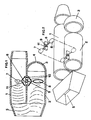
- Figure 1 shows a vertical section of a silencer device for exhausts of motors and similar with acoustic interference.
- Figure 2 shows an axonometric exploded view of the device according to figure 1.
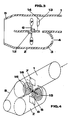
- Figure 3 shows a scheme of a mechanical variant of the device according to the present invention.
- Figure 4 shows a scheme of a variant of the device according to the present invention provided with external springs.
- the figures show a silencer device for exhausts of motors and similar with acoustic interference, consisting of a pipe 1 with walls being insulating against heat and sounds with amianthus, that may be applied, in a well known manner, to exhaust pipes of any kind, or that may be obtained inside the end part of said pipes.
- a second pipe 2 is applied parallel and out of one piece, being closed at the end of the semispherical cap 3 with hole(s) 4 for the air from the outside.
- Said parts 1 and 2 converge in the same outlet end 5 being preferably outwardly tapered.
- a main feature of the device according to the present invention consists in the rigid rod 6 passing thtrough an opening 11 provided in said parts 1 and 2, and provided with end blades 7 and 8 having their fulcrum on the spherical knot 9 or similar, placed in the point of contact of said parts of the pipes 1 and 2 and that will elastically vibrate due to the presence of springs or similar applied on both sides, under the impulse of the acoustic waves spreading in the exhausts in part 1 and acting onto blade 7 so that the corresponding blade 8 produces vibrations in the air entering pipe 2 through hole 4, in perfect phase opposition with respect to the exhaust waves.
- springs 10 are replaced by an elastic blade 12 preferably out of a double steel layer or similar, for making the vibration of said rigid rod 6 elastic in correspondence with each frequence of the sound wave spreading in the exhaust and therefore in the part of pipe 1.
- the present invention provides a jet-breaker 13 fixed to the walls of pipe 1 by means of small bars 14 or similar, placed fro exactly covering blade 7 and provided with an aerodynamic shape such as to deviate the exhaust flow and to prevent said blade 7, even if always vibrating due to the resonance with the sound waves coupled to the exhaust, from getting inclined by the mechanical impact of the exhaust, improving the efficiency thereof.
- the present invention provides, in a variant, that the vibrations of the rigid rod 6 be determined, through a transversal rod 16, by helicoidal springs 15 or springs of any othe kind housed outside pipes 1 and 2, as shown in figure 4.
Landscapes
- Engineering & Computer Science (AREA)
- Chemical & Material Sciences (AREA)
- Combustion & Propulsion (AREA)
- Mechanical Engineering (AREA)
- General Engineering & Computer Science (AREA)
- Exhaust Silencers (AREA)
Claims (4)
Priority Applications (1)
| Application Number | Priority Date | Filing Date | Title |
|---|---|---|---|
| AT88908972T ATE81386T1 (de) | 1987-10-12 | 1988-10-11 | Motorabgasschalldaempfer mit akustischer interferenz. |
Applications Claiming Priority (2)
| Application Number | Priority Date | Filing Date | Title |
|---|---|---|---|
| IT4848887 | 1987-10-12 | ||
| IT8748488A IT1211848B (it) | 1987-10-12 | 1987-10-12 | Dispositivo silenziatore per scarichi di motori e simili,ad interferenza acustica |
Publications (2)
| Publication Number | Publication Date |
|---|---|
| EP0335941A1 EP0335941A1 (de) | 1989-10-11 |
| EP0335941B1 true EP0335941B1 (de) | 1992-10-07 |
Family
ID=11266865
Family Applications (1)
| Application Number | Title | Priority Date | Filing Date |
|---|---|---|---|
| EP88908972A Expired EP0335941B1 (de) | 1987-10-12 | 1988-10-11 | Motorabgasschalldämpfer mit akustischer interferenz |
Country Status (7)
| Country | Link |
|---|---|
| US (1) | US5058702A (de) |
| EP (1) | EP0335941B1 (de) |
| JP (1) | JPH02501585A (de) |
| AT (1) | ATE81386T1 (de) |
| DE (1) | DE3875239T2 (de) |
| IT (1) | IT1211848B (de) |
| WO (1) | WO1989003472A2 (de) |
Cited By (1)
| Publication number | Priority date | Publication date | Assignee | Title |
|---|---|---|---|---|
| DE102008019488A1 (de) | 2008-04-17 | 2009-10-22 | Behr Gmbh & Co. Kg | Fluiddruckpulsationsdämpfungsvorrichtung |
Families Citing this family (9)
| Publication number | Priority date | Publication date | Assignee | Title |
|---|---|---|---|---|
| WO2000047877A1 (en) * | 1999-02-09 | 2000-08-17 | Konstantin Stakhnov | The method of neutralization of used gases and reduction of the noise of exhaust of internal combustion engine and device for its execution (variants) |
| EP1246162A1 (de) | 2001-03-27 | 2002-10-02 | Recherche et Développement GROUPE COCKERILL SAMBRE | Hülle oder Wände mit verstellbaren Schalldämmungs- und/oder Schallabsorptionseigenschaften |
| US6932189B2 (en) | 2001-09-24 | 2005-08-23 | Daimlerchrysler Ag | Device for noise structuring in a motor vehicle |
| DE10222507A1 (de) * | 2001-09-24 | 2003-05-08 | Daimler Chrysler Ag | Vorrichtung zur Geräuschgestaltung bei einem Kraftfahrzeug |
| FR2838476B1 (fr) * | 2002-04-12 | 2005-06-24 | Faurecia Sys Echappement | Volume d'echappement comportant une enveloppe delimitant un passage de circulation des gaz |
| JP4677744B2 (ja) * | 2003-11-04 | 2011-04-27 | ソニー株式会社 | 噴流発生装置、電子機器及び噴流発生方法 |
| DE102004041699A1 (de) * | 2004-08-28 | 2006-03-02 | Mann + Hummel Gmbh | Vorrichtung zur Geräuschübertragung in einem Kraftfahrzeug |
| US20120285667A1 (en) * | 2011-05-13 | 2012-11-15 | Lighting Science Group Corporation | Sound baffling cooling system for led thermal management and associated methods |
| WO2017042784A1 (en) * | 2016-07-20 | 2017-03-16 | Universidad Tecnológica De Panamá | Device and method for silencing noise acoustic waves |
Family Cites Families (5)
| Publication number | Priority date | Publication date | Assignee | Title |
|---|---|---|---|---|
| FR1194562A (fr) * | 1958-04-11 | 1959-11-10 | Perfectionnements aux silencieux pour moteurs à combustion interne | |
| FR1478901A (fr) * | 1966-05-05 | 1967-04-28 | Dispositif de conduit d'échappement de véhicule à moteur et autres | |
| US3396812A (en) * | 1967-07-05 | 1968-08-13 | Arvin Ind Inc | Acoustic quarter wave tube |
| SU560952A1 (ru) * | 1975-09-10 | 1977-06-05 | Звукоизолирующа перегородка | |
| GB1583758A (en) * | 1976-10-01 | 1981-02-04 | Nat Res Dev | Attenuation of sound waves in ducts |
-
1987
- 1987-10-12 IT IT8748488A patent/IT1211848B/it active
-
1988
- 1988-10-11 US US07/362,391 patent/US5058702A/en not_active Expired - Fee Related
- 1988-10-11 EP EP88908972A patent/EP0335941B1/de not_active Expired
- 1988-10-11 WO PCT/IT1988/000072 patent/WO1989003472A2/en not_active Ceased
- 1988-10-11 AT AT88908972T patent/ATE81386T1/de not_active IP Right Cessation
- 1988-10-11 DE DE8888908972T patent/DE3875239T2/de not_active Expired - Fee Related
- 1988-10-11 JP JP63508293A patent/JPH02501585A/ja active Pending
Cited By (2)
| Publication number | Priority date | Publication date | Assignee | Title |
|---|---|---|---|---|
| DE102008019488A1 (de) | 2008-04-17 | 2009-10-22 | Behr Gmbh & Co. Kg | Fluiddruckpulsationsdämpfungsvorrichtung |
| EP2116752A1 (de) | 2008-04-17 | 2009-11-11 | Behr GmbH & Co. KG | Fluiddruckpulsationsdämpfungsvorrichtung |
Also Published As
| Publication number | Publication date |
|---|---|
| WO1989003472A2 (en) | 1989-04-20 |
| IT8748488A0 (it) | 1987-10-12 |
| EP0335941A1 (de) | 1989-10-11 |
| ATE81386T1 (de) | 1992-10-15 |
| DE3875239T2 (de) | 1993-09-16 |
| IT1211848B (it) | 1989-11-03 |
| US5058702A (en) | 1991-10-22 |
| DE3875239D1 (de) | 1992-11-12 |
| JPH02501585A (ja) | 1990-05-31 |
| WO1989003472A3 (en) | 1989-05-05 |
Similar Documents
| Publication | Publication Date | Title |
|---|---|---|
| US2046193A (en) | Muffler | |
| EP0335941B1 (de) | Motorabgasschalldämpfer mit akustischer interferenz | |
| US5655367A (en) | Inlet or exhaust line for a reciprocating machine | |
| JPH05231316A (ja) | 圧縮機の吐出ガス消音器 | |
| US1844104A (en) | Exhaust muffler | |
| US2138510A (en) | Muffler | |
| Rahman et al. | Design and construction of a muffler for engine exhaust noise reduction | |
| Tandon | Noise-reducing designs of machines and structures | |
| US3823796A (en) | Mufflers for internal combustion engines | |
| JPS58202322A (ja) | 内燃機関の排気消音装置 | |
| US2690812A (en) | Muffler construction | |
| US3515241A (en) | Coiled wire element | |
| US20050061578A1 (en) | Muffling device and method for internal combustion engine | |
| RU2131519C1 (ru) | Система выхлопа энергетической установки | |
| CN219431917U (zh) | 一种柴油发电机组消音器 | |
| JPH10252442A (ja) | 内燃機関用消音器 | |
| SU1483061A1 (ru) | Глушитель шума выпуска двигател внутреннего сгорани | |
| JPH0543262Y2 (de) | ||
| JPS58202321A (ja) | 内燃機関の排気消音装置 | |
| RU96108017A (ru) | Резонатор, объединенный с глушителем шума выхлопа двигателя внутреннего сгорания. (резоглушитель) | |
| RU2033534C1 (ru) | Глушитель шума выхлопа двигателя внутреннего сгорания | |
| SU1622598A1 (ru) | Глушитель шума выхлопа двигател внутреннего сгорани | |
| RU2023173C1 (ru) | Глушитель шума | |
| RU2268374C2 (ru) | Глушитель шума выхлопа двигателя внутреннего сгорания | |
| RU61350U1 (ru) | Глушитель шума выхлопа двигателя внутреннего сгорания |
Legal Events
| Date | Code | Title | Description |
|---|---|---|---|
| PUAI | Public reference made under article 153(3) epc to a published international application that has entered the european phase |
Free format text: ORIGINAL CODE: 0009012 |
|
| 17P | Request for examination filed |
Effective date: 19890601 |
|
| AK | Designated contracting states |
Kind code of ref document: A1 Designated state(s): AT BE CH DE FR GB LI NL SE |
|
| 17Q | First examination report despatched |
Effective date: 19910408 |
|
| GRAA | (expected) grant |
Free format text: ORIGINAL CODE: 0009210 |
|
| AK | Designated contracting states |
Kind code of ref document: B1 Designated state(s): AT BE CH DE FR GB LI NL SE |
|
| PG25 | Lapsed in a contracting state [announced via postgrant information from national office to epo] |
Ref country code: SE Effective date: 19921007 Ref country code: NL Effective date: 19921007 Ref country code: BE Effective date: 19921007 Ref country code: AT Effective date: 19921007 |
|
| REF | Corresponds to: |
Ref document number: 81386 Country of ref document: AT Date of ref document: 19921015 Kind code of ref document: T |
|
| REF | Corresponds to: |
Ref document number: 3875239 Country of ref document: DE Date of ref document: 19921112 |
|
| EN | Fr: translation not filed | ||
| NLV1 | Nl: lapsed or annulled due to failure to fulfill the requirements of art. 29p and 29m of the patents act | ||
| NLXE | Nl: other communications concerning ep-patents (part 3 heading xe) |
Free format text: A REQUEST FOR RESTORATION TO THE PRIOR STATE HAS BEEN FILED ON 930310 |
|
| ET | Fr: translation filed | ||
| REG | Reference to a national code |
Ref country code: FR Ref legal event code: AR |
|
| REG | Reference to a national code |
Ref country code: FR Ref legal event code: BR |
|
| PLBE | No opposition filed within time limit |
Free format text: ORIGINAL CODE: 0009261 |
|
| STAA | Information on the status of an ep patent application or granted ep patent |
Free format text: STATUS: NO OPPOSITION FILED WITHIN TIME LIMIT |
|
| 26N | No opposition filed | ||
| NLXE | Nl: other communications concerning ep-patents (part 3 heading xe) |
Free format text: THE REQUEST FOR RESTORATION TO THE PRIOR STATE AS PROVIDED FOR IN ART. 17A OF THE PATENTS ACT HAS BEEN REJECTED ON 940211 |
|
| PGFP | Annual fee paid to national office [announced via postgrant information from national office to epo] |
Ref country code: GB Payment date: 19981016 Year of fee payment: 11 |
|
| PGFP | Annual fee paid to national office [announced via postgrant information from national office to epo] |
Ref country code: FR Payment date: 19990330 Year of fee payment: 11 |
|
| PGFP | Annual fee paid to national office [announced via postgrant information from national office to epo] |
Ref country code: CH Payment date: 19990428 Year of fee payment: 11 |
|
| PGFP | Annual fee paid to national office [announced via postgrant information from national office to epo] |
Ref country code: DE Payment date: 19990727 Year of fee payment: 11 |
|
| PG25 | Lapsed in a contracting state [announced via postgrant information from national office to epo] |
Ref country code: GB Free format text: LAPSE BECAUSE OF NON-PAYMENT OF DUE FEES Effective date: 19991011 |
|
| PG25 | Lapsed in a contracting state [announced via postgrant information from national office to epo] |
Ref country code: LI Free format text: LAPSE BECAUSE OF NON-PAYMENT OF DUE FEES Effective date: 19991031 Ref country code: CH Free format text: LAPSE BECAUSE OF NON-PAYMENT OF DUE FEES Effective date: 19991031 |
|
| GBPC | Gb: european patent ceased through non-payment of renewal fee |
Effective date: 19991011 |
|
| REG | Reference to a national code |
Ref country code: CH Ref legal event code: PL |
|
| PG25 | Lapsed in a contracting state [announced via postgrant information from national office to epo] |
Ref country code: FR Free format text: LAPSE BECAUSE OF NON-PAYMENT OF DUE FEES Effective date: 20000630 |
|
| PG25 | Lapsed in a contracting state [announced via postgrant information from national office to epo] |
Ref country code: DE Free format text: LAPSE BECAUSE OF NON-PAYMENT OF DUE FEES Effective date: 20000801 |
|
| REG | Reference to a national code |
Ref country code: FR Ref legal event code: ST |