EP0335600A1 - Elastischer Reibstoff - Google Patents
Elastischer Reibstoff Download PDFInfo
- Publication number
- EP0335600A1 EP0335600A1 EP89302920A EP89302920A EP0335600A1 EP 0335600 A1 EP0335600 A1 EP 0335600A1 EP 89302920 A EP89302920 A EP 89302920A EP 89302920 A EP89302920 A EP 89302920A EP 0335600 A1 EP0335600 A1 EP 0335600A1
- Authority
- EP
- European Patent Office
- Prior art keywords
- composite material
- carbon
- adhesive
- resiliency
- pressure
- Prior art date
- Legal status (The legal status is an assumption and is not a legal conclusion. Google has not performed a legal analysis and makes no representation as to the accuracy of the status listed.)
- Granted
Links
- 239000002783 friction material Substances 0.000 title claims abstract description 12
- 239000000463 material Substances 0.000 claims abstract description 48
- OKTJSMMVPCPJKN-UHFFFAOYSA-N Carbon Chemical compound [C] OKTJSMMVPCPJKN-UHFFFAOYSA-N 0.000 claims abstract description 45
- 229910052799 carbon Inorganic materials 0.000 claims abstract description 43
- 238000000034 method Methods 0.000 claims abstract description 28
- 230000008569 process Effects 0.000 claims abstract description 20
- 239000004744 fabric Substances 0.000 claims abstract description 15
- 239000002356 single layer Substances 0.000 claims abstract description 5
- 239000002131 composite material Substances 0.000 claims description 49
- 239000000853 adhesive Substances 0.000 claims description 34
- 230000001070 adhesive effect Effects 0.000 claims description 34
- 238000005229 chemical vapour deposition Methods 0.000 claims description 20
- 239000000758 substrate Substances 0.000 claims description 20
- 239000011148 porous material Substances 0.000 claims description 11
- 230000000694 effects Effects 0.000 claims description 9
- 239000000835 fiber Substances 0.000 claims description 8
- 229920000049 Carbon (fiber) Polymers 0.000 claims description 6
- 239000004917 carbon fiber Substances 0.000 claims description 6
- 230000004044 response Effects 0.000 claims description 6
- 239000011248 coating agent Substances 0.000 claims description 4
- 238000000576 coating method Methods 0.000 claims description 4
- 238000005520 cutting process Methods 0.000 claims description 4
- 239000007788 liquid Substances 0.000 claims description 4
- 238000004891 communication Methods 0.000 claims description 3
- 239000002826 coolant Substances 0.000 claims description 3
- 239000000126 substance Substances 0.000 claims description 2
- 238000009941 weaving Methods 0.000 claims description 2
- 238000001125 extrusion Methods 0.000 claims 4
- 238000000151 deposition Methods 0.000 claims 1
- 230000008021 deposition Effects 0.000 claims 1
- 239000002657 fibrous material Substances 0.000 claims 1
- 238000005234 chemical deposition Methods 0.000 abstract 1
- 230000005540 biological transmission Effects 0.000 description 11
- 230000000903 blocking effect Effects 0.000 description 7
- 230000000712 assembly Effects 0.000 description 6
- 238000000429 assembly Methods 0.000 description 6
- 239000002296 pyrolytic carbon Substances 0.000 description 5
- 230000007935 neutral effect Effects 0.000 description 4
- 230000008859 change Effects 0.000 description 3
- 150000001875 compounds Chemical class 0.000 description 3
- 238000012360 testing method Methods 0.000 description 3
- 230000009471 action Effects 0.000 description 2
- 238000000280 densification Methods 0.000 description 2
- 229910002804 graphite Inorganic materials 0.000 description 2
- 239000010439 graphite Substances 0.000 description 2
- 238000010438 heat treatment Methods 0.000 description 2
- 238000004519 manufacturing process Methods 0.000 description 2
- 230000007246 mechanism Effects 0.000 description 2
- 238000012986 modification Methods 0.000 description 2
- 230000004048 modification Effects 0.000 description 2
- 230000035515 penetration Effects 0.000 description 2
- 230000002028 premature Effects 0.000 description 2
- 229920000297 Rayon Polymers 0.000 description 1
- 238000010923 batch production Methods 0.000 description 1
- 238000005219 brazing Methods 0.000 description 1
- 238000010924 continuous production Methods 0.000 description 1
- 239000012809 cooling fluid Substances 0.000 description 1
- 238000013461 design Methods 0.000 description 1
- 238000013007 heat curing Methods 0.000 description 1
- 239000010410 layer Substances 0.000 description 1
- 230000013011 mating Effects 0.000 description 1
- 239000002964 rayon Substances 0.000 description 1
- 230000009467 reduction Effects 0.000 description 1
- 230000000717 retained effect Effects 0.000 description 1
- 238000005096 rolling process Methods 0.000 description 1
- 238000010008 shearing Methods 0.000 description 1
- 230000001360 synchronised effect Effects 0.000 description 1
- 239000002699 waste material Substances 0.000 description 1
- 239000002759 woven fabric Substances 0.000 description 1
Images


Classifications
-
- F—MECHANICAL ENGINEERING; LIGHTING; HEATING; WEAPONS; BLASTING
- F16—ENGINEERING ELEMENTS AND UNITS; GENERAL MEASURES FOR PRODUCING AND MAINTAINING EFFECTIVE FUNCTIONING OF MACHINES OR INSTALLATIONS; THERMAL INSULATION IN GENERAL
- F16D—COUPLINGS FOR TRANSMITTING ROTATION; CLUTCHES; BRAKES
- F16D69/00—Friction linings; Attachment thereof; Selection of coacting friction substances or surfaces
- F16D69/02—Composition of linings ; Methods of manufacturing
- F16D69/023—Composite materials containing carbon and carbon fibres or fibres made of carbonizable material
-
- F—MECHANICAL ENGINEERING; LIGHTING; HEATING; WEAPONS; BLASTING
- F16—ENGINEERING ELEMENTS AND UNITS; GENERAL MEASURES FOR PRODUCING AND MAINTAINING EFFECTIVE FUNCTIONING OF MACHINES OR INSTALLATIONS; THERMAL INSULATION IN GENERAL
- F16D—COUPLINGS FOR TRANSMITTING ROTATION; CLUTCHES; BRAKES
- F16D23/00—Details of mechanically-actuated clutches not specific for one distinct type
- F16D23/02—Arrangements for synchronisation, also for power-operated clutches
- F16D23/04—Arrangements for synchronisation, also for power-operated clutches with an additional friction clutch
- F16D23/06—Arrangements for synchronisation, also for power-operated clutches with an additional friction clutch and a blocking mechanism preventing the engagement of the main clutch prior to synchronisation
-
- F—MECHANICAL ENGINEERING; LIGHTING; HEATING; WEAPONS; BLASTING
- F16—ENGINEERING ELEMENTS AND UNITS; GENERAL MEASURES FOR PRODUCING AND MAINTAINING EFFECTIVE FUNCTIONING OF MACHINES OR INSTALLATIONS; THERMAL INSULATION IN GENERAL
- F16D—COUPLINGS FOR TRANSMITTING ROTATION; CLUTCHES; BRAKES
- F16D2300/00—Special features for couplings or clutches
- F16D2300/10—Surface characteristics; Details related to material surfaces
Definitions
- This invention relates to liquid cooled, frictionally engaged, energy absorbing devices such as clutches and brakes. More specifically, the invention relates to an openly porous, resilient friction material and to a method of affixing the material to a support member.
- Blocker-clutch assemblies used in these change gear transmissions include first and second positive or jaw clutches which are axially moved between engaged and disengaged positions to effect gear changes.
- Each assembly includes a frictionally engagable blocker ring which prevents asynchronous engagement of the jaw clutches in response to initial engaging movement thereof.
- the blocker ring is supported by the first jaw clutch for limited rotation relative thereto and includes a friction surface which engages a second friction surface, secured for rotation with the second jaw clutch, in response to the initial engaging movement of the jaw clutches. If the jaw clutches are rotating at different speeds during the initial engaging movement thereof, the frictional engagement effects limited rotation of the blocker ring to a position blocking engagement of the jaw clutches until substantial synchronization of the jaw clutches is achieved.
- blocker-clutch assemblies have greatly reduced the complexity and effort required to effect gear changes.
- blocker rings have been known to prematurely move to the unblocking position before the jaw clutches reach synchronism or substantially synchronous speeds, thereby allowing asynchronous engagement of the jaw clutch teeth with resultant excessive wear thereto and in some cases failure of the jaw clutches.
- An object of the invention is to provide an openly porous, resilient friction material for a friction energy absorbing device.
- Another object of the invention is to provide such a friction material for friction means in synchronizer or blocker assemblies used in step ratio transmissions.
- an energy absorbing device includes at least two relatively rotatable members with confronting function surfaces engagable to retard the relative rotation; an openly porous carbon/carbon composite material affixed to at least one of the members for defining at least one of the friction surfaces, the material including a substrate defined by a carbon fiberous material woven into a single layer substrate or fabric and coated with carbon deposited thereon by chemical vapor deposition process to a density of 0.3 to 1.3 g/cc; a liquid coolant in communication with the surfaces; and an actuator means for effecting frictional engagement of the surfaces.
- the invention is characterized by the fiberous material and weave being formed to provide the substrate with resiliency in a direction normal to the plane of the weave before and after the chemical vapor deposition process; and the composite being affixed to the one member in a manner substantially preserving the resiliency.
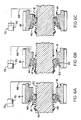
- FIG. 1 therein is illustrated a blocker-clutch assembly 10 having first and second positive clutch members 12,14 and a blocker mechanism 16 for preventing asynchronous engagement of the clutch members which are respectively connected to a shaft 20 and a gear 18.
- Gear 18 and shaft 20 may form part of a 4 X 3 compound transmission such as the twelve forward speed, semi-blocked splitter type compound transmission disclosed in U.S. Patent 4,703,667.
- shaft 20 would be a transmission main shaft disposed at an extension of its left end into a main transmission section having four change speed ratios.
- Gear 18 would be a constant mesh splitter gear disposed in an auxiliary transmission section.
- Clutch member 12 is provided with internal splines 22 which are disposed with corresponding external splines 24 provided on shaft 20 for interconnecting clutch member 12 to the shaft for rotation therewith.
- the cooperating splines permit clutch member to freely slide axially relative to shaft 20.
- a stop ring 26 is seated within a suitable groove formed in the external periphery of the shaft and disposed for contacting clutch member 12 and limiting rightward axial movement thereof.
- Clutch member 12 is resiliently urged rightward by a spring 28 which reacts at its left end against a spring seat 30 secured to shaft 20 in a manner similar to stop ring 26.
- Clutch member 12 is provided with external spline teeth 32 thereon which are adapted to meshingly engage internal spline teeth 34 of clutch member 14 provided on gear 18.
- Teeth 32 of clutch member 12 are tapered, as at 36, in a manner similar to the leading edge 38 of teeth 34 on gear 18.
- the tapered conical surface defined by the tapered leading edges extends at an angle of between 30′ and 40′ relative to the longitudinal axis of the shaft. The exact degree of taper and the advantages thereof are explained in detail in U.S. Patent 3,265,173.
- a selected number, herein three, of external spline teeth 32 are partially removed for permitting the presence of a blocker ring 40 of the blocker mechanism which is further described hereinafter.
- Such partial removal leaves three axially shortened blocker tooth portions 42 for cooperating with blocker ring 40.
- the tooth portions are disposed in a common plane and circumferentially spaced equal distances apart; however, an asymmetrical arrangement such as disclosed in U.S. Patent 4,703,667 may be used in some applications.
- the blocker ring comprises a nondeformable ring encircling clutch member 12.
- the ring includes an appropriate number, herein three pairs, of radially inwardly extending projections 44,46 which, when properly positioned, mate with external spline teeth 32.
- Each pair of projections 44,46 have a total circumferential dimension less than the corresponding circumferential spaces defined by partially removing the tooth portions, thereby allowing limited clockwise and counterclockwise rotation of the blocker ring relative to clutch member 12 from a position seen in Figure 3 wherein the spaces between tooth projections 44,46 align with tooth portions 42.
- each inwardly projecting tooth pair 44,46 has a clearance distance wider than the corresponding circumferential dimension of tooth portions 42 so that when properly aligned at synchronism (or more accurately when the relative speeds of blocker ring 40 and clutch member 12 cross synchronism) the tooth projections 44,46 will straddle tooth portions 42 and clutch member 12 can move axially through but not past blocker ring to effect engagement with spline teeth 34 of gear 18.
- each tooth portion 42 is also preferably provided with tapers or ramps 52,54 corresponding with tapers or ramps 48,50.
- the angles 56 of the ramps 48-54 are selected such that blocking teeth 44,46 and tooth portions 42 remain in proper blocked position when unshown but previously mentioned main transmission section at the left end of shaft 20 is not in neutral, but will tend under a contacting force, such as the force provided by spring 28, to cause the blocker and clutch member to assume a nonblocking position when the main transmission is in neutral and the gear 18 has been selected for engagement.
- Such ramps are known in the art as sensor unblocking ramps.
- Ramp angles 56 of about 15°-25°, preferably 20°, relative to a plane P normal to the axis of rotation of shaft 20 have proven highly satisfactory for most known semi-blocked transmissions.
- the radially inner side of blocker ring 40 may be provided with a groove 58 which receives a split, annular, resilient ring 60.
- Ring 60 is normally of slightly less internal diameter than the external diameter of clutch member teeth 34 so that when the parts are in the assembled condition, ring 60 is distorted slightly outwardly to thereby exert a light but definite resilient clamping pressure against the external surfaces of teeth 34.
- the resilient clamping pressure effects a significant resistance to axial movement between the blocker ring and clutch member but only an insignificant resistance to relative rotative movement therebetween.
- Blocker ring 40 includes a generally outward facing frustum of a cone shape or frustoconical surface 62 positioned to frictionally engage a generally inwardly facing frustum of a cone or frustoconical surface 64 on a radially inner wall of gear 18 in response to initial axial engaging movement of gear 18 leftward by a shift fork 66 schematically illustrated in Figures 6.
- the axial drag provided by resilient ring 60 resists axial movement of blocker ring 40 relative to clutch member 12 which is biased rightward by spring 28. Accordingly, ring 60 functions as a pre-energizer ring whose axial drag effects initial engagement of the surfaces 62,64 prior to axial movement of the blocker ring 40.
- a stop ring 68 limits movement of blocker ring 40 away from frustoconical surface 64 when gear 18 is moved rightward to effect disengagement of positive clutch members 12,14.
- Blocker-clutch assembly 10 is generally known in the prior as may be seen by reference to previously mentioned U.S. Patent 4,703,667.
- Such assemblies provide for preselection of the ratio gears they are associated with, e.g., the actuating means (shift fork 66 and piston 72) for engaging the positive clutch members 12,14 may be fully displaced prior to synchronism therebetween. Actual engagement of the positive clutch members occurs at a later time, as may be seen by reference to Figures 6A-6C. Briefly, Figure 6A illustrates a neutral or nonselected position of blocker-clutch assembly 10.
- Figure 6B illustrates a preselected position wherein gear 18, clutch member 14, shift fork 60, and piston 72 are fully displaced with clutch member 12 moved leftward against the bias force of spring 28 and with frustoconical surfaces 62,64 frictionally engaged to maintain a blocking position until synchronism is crossed due to manual or automatic means changing the speed of shaft 20 and/or gear 18.
- Such means are known and are typically provided by changes in the speed of a prime mover connected to shaft 20 and/or by use of a brake connected to the shaft or gear.
- the biasing force of spring 28 moves or fires clutch member 12 into engagement with clutch member 14. Since relatively high synchronism crossing rates often occur, spring 28 must provide sufficient force to quickly move clutch member 12 into engagement.
- Figure 6C illustrates the engaged position of the positive clutch members.
- blocker-clutch assemblies having unblocking ramps such as ramps 48-54
- ramps 48-54 have a tendency under certain dynamic operating conditions to prematurely unblock or crash and allow nonsynchronous engagement of clutch members 12,14.
- an improved friction material configuration at the interface of the frustoconical surfaces which has, to date, completely solved the premature unblocking or crash problem while at the same time substantially reducing manufacturing cost of the blocker-clutch assemblies.
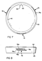
- Figures 7, 8 illustrate the configuration and position of the material on blocker ring surface 62.
- the material 74 is preferably formed of a single woven layer substrate of carbon fibers coated or infiltrated by chemical vapor deposition (CVD) process with pyrolytic carbon.
- the fibers may be formed of many known materials, but are preferably formed of carbonized rayon or polyacrylinitrite (PAN).
- PAN polyacrylinitrite
- carbon filaments may be used in lieu of fibers provided the weave of the fabric is sufficiently resilient in directions normal to the plane of the fabric, i.e., direction normal to the friction plane of the material when it is in use.
- Acceptable CVD processes are taught in U.S. Patents 4,291,794 and 3,944,686; the first patent teaches a batch process and the second a continuous process.
- the composite may have a density range of 0.3 to 1.3 gm/cc after the CVD process and prior to bonding to surface 62.
- material on the low end of this range may have a higher wear rate.
- Material on the high end of the range is currently more expensive and may tend to be too rigid for optimism performance. Accordingly, a range of 0.7 to 1.1 gm/cc is considered to be some what more optimum.
- Manufacturing specifications for this material require the fibers to be based on PAN filaments chopped and spun into yarn; the yarn weight to be 2/10 worsted count; the fabric weave to be 2 X 2 equally tensioned basket square weave at 18 to 22 pairs per inch (2.54 cm); the density to be 0.8 to 1.1 gm/cc by CVD densification at temperatures not to exceed 1,200°C; and the thickness to be 0.045 inches (0.11 cm).
- the texture of the densified or finished material is substantially the same to the naked eye as the woven fabric substrate.
- the finished material is relatively flexible; is relatively resilient in the previously mentioned direction normal to the plane of the fabric with such resiliently being attributed to the use of spun yarns, weave, and density; and is openly porous with many to the pores being through pores.
- Carbon/carbon composite materials comprised of substrates formed of woven carbon fiberous yarns (particularly, yarns of twisted carbon fibers) coated or densified with pyrolytic carbon by CVD process to densities less than 1.3 gm/cc have exhibited greater resistency in all directions than do composite materials comprised of substrates for of cmoparable amounts of woven carbon fibrous strands coated or defined with carbon by CVD process to comparable densities.
- Minimum waste of material 74 is achieved by cutting the material into polygonal segments 76 which may be circumferentially spaced apart when affixed or bonded to a support member such as surface 62 of blocker ring 40. Alternatively, the segments may abut each other to define a continuous friction ring surface. When the segments are circumferentially spaced apart, as illustrated in Figure 7, the leading edges 76a of the segments may be disposed oblique to the direction of rotation of friction surface 76c defined by segments 76 to facilitate rapid wiping of excess oil (cooling fluid) off mating surfaces 64, thereby quickly achieving maximum or design coefficient of friction at the interface of friction material surface 76c and surface 64 in response to initial engagement due to the force transmitted by pre-energizer ring 60.
- the segments are preferably cut into parallelograms and bonded to blocker ring surface 62 with sides 76b of the material generally oriented parallel to planes extending normal to the axis of rotation; however, such orientation is not believed to be critical. Further, three substantially equally spaced segments are preferred.
- the adhesive used in the above example was B. F. Goodrich Plastilock 601 having an 8 mil. (0.2 mm) thickness.
- the spun yarns and weave of the yarns provide an openly porous substrate or fabric which is relatively resilient in the direction normal to the weave of the fabric.
- a substantial portion of the substrate open porosity and resiliency is retained by the composite material by limiting CVD coating or densification of the substrate to the range of 0.3 to 1.3 gm/cc (preferably 0.8 to 1.1 gm/cc).
- the open porosity and resiliency of the composite material in the area of its friction surface is maintained during the bonding process by using volumes of adhesive that are less than the open porosity volume of the composite, and by limiting the magnitude of the bonding process pressure for minimizing crushing the composite material and for maintaining the open porosity volume of the composite material greater than the volume of the adhesive, whereby the volume of the open pores adjacent to the bond side of the composite material consumes the adhesive while the pores adjacent to the friction side remains free of the adhesive. Bonding pressures less than 250 pounds per square inch (17.6 Kg/cm2) are considered adequate for most carbon/carbon composite materials acceptable for use with blocker-clutch assembly 10.
- unit loading on the friction surface 76c of material 74 within a range of 150-300 pounds per square inch (10-20 Kg/cm2). Since such unit loading in an assembly such as blocker-clutch assembly 10 is primarily a function of the biasing force of spring 28 and since the force of spring 28 must be within a rather narrow range, unit loading has been controlled by tailoring or configuring the surface area 76c of material 74. By way of example, crash free operation has been obtained in tests of blocker-clutch assembly 10 using three parallelogram shaped segments 76 having a combined friction surface area of 1.17 square inches (7.55 cm2).
- cone surfaces 62,64 have an angle of about 10° and a mean diameter of about 4.35 inches (11 cm)
- ramps 48-54 have an angle of about 20°
- spring 28 provides a biasing force of about 50 pounds (27 Kg) when compressed in Figure 62.
- the combined friction surface areas 76c constitute a 83% reduction in total friction material surface area relative to the blocker-clutch assembly disclosed in U.S. Patent 4,703,667 and the pressure at the interface of the combined surface areas 76c is 210 pounds per square inch (14.8 Kg/cm2).
Landscapes
- Engineering & Computer Science (AREA)
- General Engineering & Computer Science (AREA)
- Mechanical Engineering (AREA)
- Chemical & Material Sciences (AREA)
- Composite Materials (AREA)
- Materials Engineering (AREA)
- Mechanical Operated Clutches (AREA)
- Braking Arrangements (AREA)
- Ceramic Products (AREA)
Applications Claiming Priority (2)
| Application Number | Priority Date | Filing Date | Title |
|---|---|---|---|
| US17447588A | 1988-03-28 | 1988-03-28 | |
| US174475 | 1988-03-28 |
Publications (2)
| Publication Number | Publication Date |
|---|---|
| EP0335600A1 true EP0335600A1 (de) | 1989-10-04 |
| EP0335600B1 EP0335600B1 (de) | 1993-06-09 |
Family
ID=22636288
Family Applications (1)
| Application Number | Title | Priority Date | Filing Date |
|---|---|---|---|
| EP19890302920 Expired - Lifetime EP0335600B1 (de) | 1988-03-28 | 1989-03-23 | Elastischer Reibstoff |
Country Status (6)
| Country | Link |
|---|---|
| EP (1) | EP0335600B1 (de) |
| JP (1) | JP2973323B2 (de) |
| AU (1) | AU623119B2 (de) |
| BR (1) | BR8901502A (de) |
| DE (1) | DE68906944T2 (de) |
| ES (1) | ES2041409T3 (de) |
Cited By (2)
| Publication number | Priority date | Publication date | Assignee | Title |
|---|---|---|---|---|
| US6719113B2 (en) | 2000-11-07 | 2004-04-13 | Alcon Components Limited | Clutch hub |
| CN112226206A (zh) * | 2020-11-09 | 2021-01-15 | 贵阳天龙摩擦材料有限公司 | 一种整体编织型摩擦材料的制备方法 |
Families Citing this family (2)
| Publication number | Priority date | Publication date | Assignee | Title |
|---|---|---|---|---|
| JP6539121B2 (ja) * | 2015-06-11 | 2019-07-03 | 株式会社エクセディ | クラッチ装置 |
| JP7756591B2 (ja) | 2022-03-31 | 2025-10-20 | 株式会社トプコン | 眼科装置 |
Citations (4)
| Publication number | Priority date | Publication date | Assignee | Title |
|---|---|---|---|---|
| FR2369931A1 (fr) * | 1976-11-03 | 1978-06-02 | Courtaulds Ltd | Structure composite dans laquelle une matiere de matrice est renforcee par de l'etoffe |
| FR2470897A2 (fr) * | 1979-12-04 | 1981-06-12 | Peugeot | Dispositif de synchronisation pour boite de vitesses |
| US4700823A (en) * | 1980-03-28 | 1987-10-20 | Eaton Corporation | Clutch with pyrolytic carbon friction material |
| EP0292997A1 (de) * | 1987-05-29 | 1988-11-30 | Toho Rayon Co., Ltd. | Reibmaterial |
-
1989
- 1989-03-22 BR BR898901502A patent/BR8901502A/pt not_active IP Right Cessation
- 1989-03-23 DE DE1989606944 patent/DE68906944T2/de not_active Expired - Fee Related
- 1989-03-23 EP EP19890302920 patent/EP0335600B1/de not_active Expired - Lifetime
- 1989-03-23 AU AU31685/89A patent/AU623119B2/en not_active Ceased
- 1989-03-23 ES ES89302920T patent/ES2041409T3/es not_active Expired - Lifetime
- 1989-03-28 JP JP1076389A patent/JP2973323B2/ja not_active Expired - Fee Related
Patent Citations (4)
| Publication number | Priority date | Publication date | Assignee | Title |
|---|---|---|---|---|
| FR2369931A1 (fr) * | 1976-11-03 | 1978-06-02 | Courtaulds Ltd | Structure composite dans laquelle une matiere de matrice est renforcee par de l'etoffe |
| FR2470897A2 (fr) * | 1979-12-04 | 1981-06-12 | Peugeot | Dispositif de synchronisation pour boite de vitesses |
| US4700823A (en) * | 1980-03-28 | 1987-10-20 | Eaton Corporation | Clutch with pyrolytic carbon friction material |
| EP0292997A1 (de) * | 1987-05-29 | 1988-11-30 | Toho Rayon Co., Ltd. | Reibmaterial |
Cited By (2)
| Publication number | Priority date | Publication date | Assignee | Title |
|---|---|---|---|---|
| US6719113B2 (en) | 2000-11-07 | 2004-04-13 | Alcon Components Limited | Clutch hub |
| CN112226206A (zh) * | 2020-11-09 | 2021-01-15 | 贵阳天龙摩擦材料有限公司 | 一种整体编织型摩擦材料的制备方法 |
Also Published As
| Publication number | Publication date |
|---|---|
| EP0335600B1 (de) | 1993-06-09 |
| DE68906944D1 (de) | 1993-07-15 |
| DE68906944T2 (de) | 1994-01-20 |
| JP2973323B2 (ja) | 1999-11-08 |
| BR8901502A (pt) | 1989-11-14 |
| AU623119B2 (en) | 1992-05-07 |
| JPH0217224A (ja) | 1990-01-22 |
| ES2041409T3 (es) | 1993-11-16 |
| AU3168589A (en) | 1989-09-28 |
Similar Documents
| Publication | Publication Date | Title |
|---|---|---|
| EP0335601B1 (de) | Sperrsynchronisierte Klauenkupplungsanordnung | |
| US5033596A (en) | Resilient friction material | |
| EP0393845B1 (de) | Aufspannvorrichtung und Verfahren zum Verbinden von Reibungsmaterial | |
| US5221401A (en) | Method for bonding friction material onto a frustoconical surface | |
| EP0027598B2 (de) | Systeme zur Kraftübertragung und Energieaufnehmung und Verfahren zur Herstellung | |
| US4700823A (en) | Clutch with pyrolytic carbon friction material | |
| EP0783638B1 (de) | Gewebeanordnung und verfahren zur kontrolle von flüssigkeitsfluss | |
| EP1396655B1 (de) | Reibungsmaterial mit Reibungsveränderungsschicht | |
| US5497867A (en) | Synchronizer with cone cup locater pins | |
| EP0570466B1 (de) | Bremsscheibe aus kohlenstoff-verbundwerkstoff mit positiver vibrationsdaempfung | |
| US6042500A (en) | Wet multi-disk coupling device, and an automatic transmission equipped therewith | |
| KR20050009149A (ko) | 기름 국한 슬롯을 가지는 마찰 물질 | |
| EP0335600B1 (de) | Elastischer Reibstoff | |
| US5091041A (en) | Bonding apparatus for bonding friction material | |
| EP0014718A1 (de) | Synchronisiervorrichtung für transmissionen. | |
| EP0774594B1 (de) | Synchronring | |
| US20040016619A1 (en) | Synchronizer |
Legal Events
| Date | Code | Title | Description |
|---|---|---|---|
| PUAI | Public reference made under article 153(3) epc to a published international application that has entered the european phase |
Free format text: ORIGINAL CODE: 0009012 |
|
| AK | Designated contracting states |
Kind code of ref document: A1 Designated state(s): DE ES FR GB IT SE |
|
| 17P | Request for examination filed |
Effective date: 19900403 |
|
| 17Q | First examination report despatched |
Effective date: 19910514 |
|
| GRAA | (expected) grant |
Free format text: ORIGINAL CODE: 0009210 |
|
| AK | Designated contracting states |
Kind code of ref document: B1 Designated state(s): DE ES FR GB IT SE |
|
| ITF | It: translation for a ep patent filed | ||
| REF | Corresponds to: |
Ref document number: 68906944 Country of ref document: DE Date of ref document: 19930715 |
|
| ET | Fr: translation filed | ||
| REG | Reference to a national code |
Ref country code: ES Ref legal event code: FG2A Ref document number: 2041409 Country of ref document: ES Kind code of ref document: T3 |
|
| PLBE | No opposition filed within time limit |
Free format text: ORIGINAL CODE: 0009261 |
|
| STAA | Information on the status of an ep patent application or granted ep patent |
Free format text: STATUS: NO OPPOSITION FILED WITHIN TIME LIMIT |
|
| 26N | No opposition filed | ||
| EAL | Se: european patent in force in sweden |
Ref document number: 89302920.7 |
|
| REG | Reference to a national code |
Ref country code: GB Ref legal event code: IF02 |
|
| PGFP | Annual fee paid to national office [announced via postgrant information from national office to epo] |
Ref country code: GB Payment date: 20040205 Year of fee payment: 16 |
|
| PGFP | Annual fee paid to national office [announced via postgrant information from national office to epo] |
Ref country code: FR Payment date: 20040302 Year of fee payment: 16 |
|
| PGFP | Annual fee paid to national office [announced via postgrant information from national office to epo] |
Ref country code: SE Payment date: 20040303 Year of fee payment: 16 |
|
| PGFP | Annual fee paid to national office [announced via postgrant information from national office to epo] |
Ref country code: ES Payment date: 20040322 Year of fee payment: 16 |
|
| PGFP | Annual fee paid to national office [announced via postgrant information from national office to epo] |
Ref country code: DE Payment date: 20040331 Year of fee payment: 16 |
|
| PG25 | Lapsed in a contracting state [announced via postgrant information from national office to epo] |
Ref country code: IT Free format text: LAPSE BECAUSE OF NON-PAYMENT OF DUE FEES;WARNING: LAPSES OF ITALIAN PATENTS WITH EFFECTIVE DATE BEFORE 2007 MAY HAVE OCCURRED AT ANY TIME BEFORE 2007. THE CORRECT EFFECTIVE DATE MAY BE DIFFERENT FROM THE ONE RECORDED. Effective date: 20050323 Ref country code: GB Free format text: LAPSE BECAUSE OF NON-PAYMENT OF DUE FEES Effective date: 20050323 |
|
| PG25 | Lapsed in a contracting state [announced via postgrant information from national office to epo] |
Ref country code: SE Free format text: LAPSE BECAUSE OF NON-PAYMENT OF DUE FEES Effective date: 20050324 |
|
| PG25 | Lapsed in a contracting state [announced via postgrant information from national office to epo] |
Ref country code: ES Free format text: LAPSE BECAUSE OF NON-PAYMENT OF DUE FEES Effective date: 20050326 |
|
| PG25 | Lapsed in a contracting state [announced via postgrant information from national office to epo] |
Ref country code: DE Free format text: LAPSE BECAUSE OF NON-PAYMENT OF DUE FEES Effective date: 20051001 |
|
| EUG | Se: european patent has lapsed | ||
| GBPC | Gb: european patent ceased through non-payment of renewal fee |
Effective date: 20050323 |
|
| PG25 | Lapsed in a contracting state [announced via postgrant information from national office to epo] |
Ref country code: FR Free format text: LAPSE BECAUSE OF NON-PAYMENT OF DUE FEES Effective date: 20051130 |
|
| REG | Reference to a national code |
Ref country code: FR Ref legal event code: ST Effective date: 20051130 |
|
| REG | Reference to a national code |
Ref country code: ES Ref legal event code: FD2A Effective date: 20050326 |