EP0335268A2 - Cellule de détection pour la chromatographie de liquide - Google Patents
Cellule de détection pour la chromatographie de liquide Download PDFInfo
- Publication number
- EP0335268A2 EP0335268A2 EP89105263A EP89105263A EP0335268A2 EP 0335268 A2 EP0335268 A2 EP 0335268A2 EP 89105263 A EP89105263 A EP 89105263A EP 89105263 A EP89105263 A EP 89105263A EP 0335268 A2 EP0335268 A2 EP 0335268A2
- Authority
- EP
- European Patent Office
- Prior art keywords
- bore
- cell assembly
- detector cell
- assembly according
- polymeric
- Prior art date
- Legal status (The legal status is an assumption and is not a legal conclusion. Google has not performed a legal analysis and makes no representation as to the accuracy of the status listed.)
- Granted
Links
Images
Classifications
-
- G—PHYSICS
- G01—MEASURING; TESTING
- G01N—INVESTIGATING OR ANALYSING MATERIALS BY DETERMINING THEIR CHEMICAL OR PHYSICAL PROPERTIES
- G01N30/00—Investigating or analysing materials by separation into components using adsorption, absorption or similar phenomena or using ion-exchange, e.g. chromatography or field flow fractionation
- G01N30/02—Column chromatography
- G01N30/62—Detectors specially adapted therefor
- G01N30/74—Optical detectors
-
- G—PHYSICS
- G01—MEASURING; TESTING
- G01N—INVESTIGATING OR ANALYSING MATERIALS BY DETERMINING THEIR CHEMICAL OR PHYSICAL PROPERTIES
- G01N21/00—Investigating or analysing materials by the use of optical means, i.e. using sub-millimetre waves, infrared, visible or ultraviolet light
- G01N21/01—Arrangements or apparatus for facilitating the optical investigation
- G01N21/03—Cuvette constructions
- G01N21/05—Flow-through cuvettes
-
- G—PHYSICS
- G01—MEASURING; TESTING
- G01N—INVESTIGATING OR ANALYSING MATERIALS BY DETERMINING THEIR CHEMICAL OR PHYSICAL PROPERTIES
- G01N21/00—Investigating or analysing materials by the use of optical means, i.e. using sub-millimetre waves, infrared, visible or ultraviolet light
- G01N21/01—Arrangements or apparatus for facilitating the optical investigation
- G01N21/03—Cuvette constructions
- G01N2021/0346—Capillary cells; Microcells
-
- G—PHYSICS
- G01—MEASURING; TESTING
- G01N—INVESTIGATING OR ANALYSING MATERIALS BY DETERMINING THEIR CHEMICAL OR PHYSICAL PROPERTIES
- G01N30/00—Investigating or analysing materials by separation into components using adsorption, absorption or similar phenomena or using ion-exchange, e.g. chromatography or field flow fractionation
- G01N30/02—Column chromatography
- G01N30/62—Detectors specially adapted therefor
- G01N30/74—Optical detectors
- G01N2030/746—Optical detectors detecting along the line of flow, e.g. axial
-
- G—PHYSICS
- G01—MEASURING; TESTING
- G01N—INVESTIGATING OR ANALYSING MATERIALS BY DETERMINING THEIR CHEMICAL OR PHYSICAL PROPERTIES
- G01N21/00—Investigating or analysing materials by the use of optical means, i.e. using sub-millimetre waves, infrared, visible or ultraviolet light
- G01N21/01—Arrangements or apparatus for facilitating the optical investigation
- G01N21/03—Cuvette constructions
- G01N21/09—Cuvette constructions adapted to resist hostile environments or corrosive or abrasive materials
Definitions
- the present invention relates to detectors for spectrophotometers and particularly to a detector for a spectrophotometer of the flow-through type utilizing variable wavelength radiation for liquid chromatography.
- LC liquid chromatography
- a substance whose quantitative presence in a sample is to be determined is dissolved in a suitable carrier solvent, separated in an LC column and flowed through a detector cell which has end windows through which ultraviolet or visible light radiation is directed. Radiation exiting from the cell falls on a photodetector whose output is recorded by suitable instrumentation which is calibrated to indicate the amount of radiation absorbed by the fluid flowing through the cell. Absorbance is customarily indicated by a graph continuously recorded on a strip chart by a pen recorder. The quantitative presence of a substance of interest is determined by measuring the area under the graph peaks which represent the amount of radiation of a particular wavelength that is absorbed, particular materials being identified by particular wavelengths characteristically absorbed by them.
- the sensitivity of a spectrophotometer detector cell is a function particularly of the stability of the base line of the graph; the graph base line is established by the absorbance of the solvent used, and will change in relation to any change in the refractive index of the solvent, which in turn will be changed by a change in the temperature of the solvent in the cell.
- the baseline changes the true peak area can not be measured accurately and the peaks themselves become less clearly defined and hence difficult to identify and measure with any reliable degree of accuracy.
- the sensitivity of the instrument which is rather limited in the best circumstance when the index of refraction of the solvent remains constant (i.e. when flow noise is at a minimum) is disproportionally reduced by any change in temperatures of the solvent, thus altering its index of refraction and increasing flow noise.
- U.S. Patent No. 4,192,614 discloses a spectrophotometer cell assembly including a cell defined by a bore through a body and closed at the ends by radiation transport windows with inlet and outlet passages through the body to the bore, so that radiation passed through the sample fluid flowing through the bore is detected by a photodetector.
- the body which is expressly disclosed to be made of a thermally conductive material, is a large thermal mass in relation to the volume of the cell.
- a tubular inlet conduit also made of a thermally conductive material, wraps around the body and connects to the inlet passage so that fluid flowing into the bore will tend to equilibrate and reach a stable temperature due to the heat sink effect of the body and conduit, thereby stabilizing the refractive index of the fluid in the bore and enhancing the sensitivity of the photodetection.
- U.S. Patent Nos. 4,598,765 and 4,589,477 also involve such apparatus and are similarly concerned about equilibrating temperature.
- Each of the three aforementioned patents teaches a complex means for heat exchanging with respect to the inlet conduit and a thermally conducting housing that forms the cell. Because of such construction with corrosion resistant metal cells with relatively small size and a requirement for precision, the prior art apparatus is quite difficult and expensive to make. Problems with the equilibration construction also include fluid mixing in the inlet tube length causing increased bandwidth of a fluid sample, and incomplete equilibration for high fluid flow rates. Also, a long inlet tube associated with the heat exchanger is more susceptible to blockage.
- objects of the present invention are to provide a spectrophotometer detector cell for liquid chromatography that is more accurate and reliable than previously known types of such detector cells; to provide such a detector cell without a requirement for heat exchange between the liquid inlet tube and a heat conducting cell body; to provide such a detector cell that is considerably easier and less expensive to fabricate; and to provide such a detector cell without gasket sealing problems associated with optical windows associated with the prior art.
- a detector cell assembly for use in a spectrophotometer including a source of radiation and a photodetector spaced from the source, the cell assembly being positionable between the radiation source and the photodetector.
- the cell assembly comprises a body having a bore therefore with open ends. Radiation transparent windows respectively close the ends of the bore. An inlet passage and an outlet passage open into the bore respectively adjacent the opposite ends thereof for flowing fluid therethrough.
- the body is thermally insulating to the fluid flowing in the bore.
- the body should have a size defined by an outer surface spaced laterally from the bore by a radial distance of at least about two times the bore diameter.
- the thermally insulating body is polymeric, and the transparent windows are optical lenses.
- the polymeric body has an outwardly facing annular surface respectively encircling each end of the bore approximately normal thereto and in contact with a corresponding surface on the respective window.
- the cell assembly further comprises urging means for urging each respective transparent window against the respective annular surface to effect a fluid seal between the polymeric body and each transparent window.
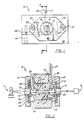
- a detector cell assembly 10 in accordance with the invention may be made as a separate unit assembly 13 adapted to be inserted as the detector cell in a multi purpose spectrophotometer, or it may be built in.
- the unit assembly 13 is shown and described as a composite unit adapted to be inserted in a multi-purpose spectrophotometer instrument.
- the unit is inserted in position for radiation from a spectrophotometer source 11 (Fig. 2) of radiation to pass through a windowed cell bore 12 of detector assembly 13 and impinge on the photosensitive surface of a photodetector 14 .
- Photodetector 14 produces output signals proportional to the radiation received, the signals thus being proportional to the amount of light absorbed by a sample fluid flowing through cell bore 12 .
- Signals from photodetector 14 are processed by means well known in the art to provide an analysis in interpretable form, such as a continuous graph produced by a pen recorder.
- Source 11 is suitably a deutrium arc lamp and the particular wavelength of the radiation to be applied to cell bore 12 is suitably selected by a monochromator or filter (not shown) in the path of the radiation from source 11 to cell bore 12 .
- End windows 16,17 which are preferably optical lenses, are each made of a suitable radiation transparent material such as quartz and are fitted in a coaxial counterbore of cell body 15 and sealed over the ends of cell bore 12 . The windows are sealed in place by means of a pressure tight seal to be described below.
- a body 15 of assembly 13 has an inlet passage 25 and an outlet passage 26 drilled through body 15 to open into bore 12 adjacent enlarged end portions of the cell bore 12 where lenses 16,17 are disposed, respectively.
- the enlarged end portions of cell bore 12 are suitably provided by further counterboring each end of the bore to provide a boss 30,31 encircling each end of bore 12 in the counterbore hole.
- inlet and outlet passages 25,26 are connected respectively to an inlet tube 27 and to an outlet tube 28 which are made of suitably corrosion resistant material. Aluminium or brass might in some cases be used for tubes 27,28 , but stainless steel or titanium or the like should be used to enable the instrument to be used for highly corrosive materials.
- Inlet tube 27 is receptive of sample liquid flow, typically a solvent and with a dissolved sample.
- Outlet tube 28 suitably leads to a waste pipe or waste container (not shown).
- body 15 is formed of a thermally insulating material, preferably a high strength, hard polymer that is also chemically resistant to any corrosive fluid likely to be passed through the cell.
- Suitable polymers for the body are Vespel (TM) polyamid from DuPont and Torlon (TM) 4203 polyamid-imid from Amoco.
- a preferred method of construction is to drill respective holes for the tubes in alignment with passages 25,26 , and cut slots 32,33 in the outer surface of the body from each hole to the corresponding end face of the body.
- Each tube 27,28 is pre-bent with an inner portion 48 and an outer portion 49 , and fitted into its hole and slot, where is is held in place with a suitable cement 34 , such as epoxy, which is also chemical resistant and preferably thermally insulating.
- a suitable cement 34 such as epoxy, which is also chemical resistant and preferably thermally insulating.
- the hole may be slightly larger than the tube to accommodate the cement.
- a suitable epoxy is EP41HT from Master Bond, Inc.
- Unit assembly 13 comprises body 15 with the inlet and outlet tubes 27,28 cemented in place.
- body 15 is fitted into a holder 36 which has a slot 38 and a screw 40 to clamp body 15 in place.
- Tubes 27,28 are curved as required to be led away from cell 10 .
- Tube 27 is shown curved half way around a shoulder cut 41 on the end of body 15 , so the tubes can be led away together.
- the unit assembly 13 is retained in a holder of a type depicted as 36 .
- holder 36 may be replaced by any other convenient shape or may be integrated into the instrument.
- body 15 being formed of thermally insulating material it is not necessary for inlet tube 27 to be associated with any heat exchanging means with the body; the tube is merely led along any convenient path, and either tube may be selected for the inlet except it is customary for the inlet to be from the bottom of bore 12 and the outlet from the top.
- the Z-shaped path of the inlet tube, bore and outlet tube is convenient and preferred.
- the body should have some significant wall thickness radially outward of the bore.
- the lateral (radial) distance from the bore to the outer surface of the body should be at least two, and preferably five, times the bore diameter.
- a 12.7mm diameter body is suitable for a 1.0 mm bore.
- lenses 16,17 are each held in place against corresponding boss 30,31 by a bushing 19 of brass or the like, having an inward flange surface 19a bearing against the outer circumferential surface of the lens and an outward flange 19b .
- Three or more Bellville spring washers 20 are placed around each of the bushings 19 and are held under compression against outward flange 19b by retaining clamps 21 which are held in place on the body by screws 22 (Fig. 1).
- the retaining clamps each have a pair of supports 50 cast therein and located under the screws to position and space the clamps on holder 36 for correct compression of springs 20 .
- Inward flange surface 19a mates with the convex outer surface of the corresponding lens such as to provide a radially inward component to the imaging force.
- the counterbore in which the lens rests generally locates the lens, and bushing 19 self centers on the lens and applies the axial sealing force toward the center of curvature of the lens.
- the low thermal conductivity of the body material which is less than about 2 BTU-in/hr ft2°F for the preferred polymers, has made it possible to eliminate the requirements of heat exchangers for cells.
- heat exchangers were designed to bring the column effluent temperature to the cell temperature before it entered the cell bore.
- the polymer body 15 of the present invention neither conducts nor releases heat to the flowing solvent, thereby maintaining stability for the given sample and obviating the necessity of heat exchangers.
- Heat exchangers of the prior art have contributed greatly to the cost of flow cells, and, at the same time, have decreased their efficiency by increasing instrumental bandwidth because the longer inlet tube allowed undesirable mixing in the fluid.
- the detector of the present invention shows improved bandwidth and little sensitivity to changes in fluid flow rate.
- Yet another advantage is low replacement cost, which is made possible in part by the elimination of the heat exchanger which had to be made part of the unit assembly.
- the surfaces should each have a contact area on the lens of between about 0.006 in2 (3.87mm2) and about 0.008 in2 (5.16mm2).
- a selected polymeric, thermally insulating material having sufficiently low creep and high modulus for each boss to deform between about 1.4 x 10 ⁇ 4 in. (3.5 x 10 ⁇ 3 mm) and about 0.5 x 10 ⁇ 4 in. (1.3 x 10 ⁇ 3 mm)
- excellent sealing is effected for high pressure liquid flow in the cell, vis. a pressure of at least 3600 psi (248 dynes/cm2).
- An additional benefit of the detector of the present invention is a substantial reduction in cost and manufacturing reliability.
- the cell is quite small, and requires precision.
- bore 12 is 1.0 cm long and 1.0 mm diameter, and inlet and outlet passages 25,26 are 0.45 mm diameter.
- Fabrication from stainless steel including tube attachment is quite difficult and labor intensive, and there has been a high scrap rate due to tool breakage, especially small drills. These problems are even more pronounced with titanium that is necessary for biotech fluids.
- Use of the polymer body, particularly with the aforementioned construction with cementing in the tubes and omission of gaskets, is a major improvement.
Landscapes
- Physics & Mathematics (AREA)
- Biochemistry (AREA)
- Health & Medical Sciences (AREA)
- Life Sciences & Earth Sciences (AREA)
- Chemical & Material Sciences (AREA)
- Analytical Chemistry (AREA)
- General Health & Medical Sciences (AREA)
- General Physics & Mathematics (AREA)
- Immunology (AREA)
- Pathology (AREA)
- Spectroscopy & Molecular Physics (AREA)
- Optical Measuring Cells (AREA)
- Spectrometry And Color Measurement (AREA)
Priority Applications (1)
| Application Number | Priority Date | Filing Date | Title |
|---|---|---|---|
| EP94109752A EP0626574B1 (fr) | 1988-04-01 | 1989-03-23 | Cellule de détection pour la chromatographie de liquide |
Applications Claiming Priority (2)
| Application Number | Priority Date | Filing Date | Title |
|---|---|---|---|
| US07/176,524 US4886356A (en) | 1988-04-01 | 1988-04-01 | Detector cell for liquid chromatography |
| US176524 | 1988-04-01 |
Related Child Applications (2)
| Application Number | Title | Priority Date | Filing Date |
|---|---|---|---|
| EP94109752.9 Division-Into | 1989-03-23 | ||
| EP94109752A Division EP0626574B1 (fr) | 1988-04-01 | 1989-03-23 | Cellule de détection pour la chromatographie de liquide |
Publications (3)
| Publication Number | Publication Date |
|---|---|
| EP0335268A2 true EP0335268A2 (fr) | 1989-10-04 |
| EP0335268A3 EP0335268A3 (fr) | 1991-03-27 |
| EP0335268B1 EP0335268B1 (fr) | 1995-07-12 |
Family
ID=22644696
Family Applications (2)
| Application Number | Title | Priority Date | Filing Date |
|---|---|---|---|
| EP89105263A Expired - Lifetime EP0335268B1 (fr) | 1988-04-01 | 1989-03-23 | Cellule de détection pour la chromatographie de liquide |
| EP94109752A Expired - Lifetime EP0626574B1 (fr) | 1988-04-01 | 1989-03-23 | Cellule de détection pour la chromatographie de liquide |
Family Applications After (1)
| Application Number | Title | Priority Date | Filing Date |
|---|---|---|---|
| EP94109752A Expired - Lifetime EP0626574B1 (fr) | 1988-04-01 | 1989-03-23 | Cellule de détection pour la chromatographie de liquide |
Country Status (4)
| Country | Link |
|---|---|
| US (1) | US4886356A (fr) |
| EP (2) | EP0335268B1 (fr) |
| JP (1) | JP3016789B2 (fr) |
| DE (2) | DE68929446T2 (fr) |
Cited By (5)
| Publication number | Priority date | Publication date | Assignee | Title |
|---|---|---|---|---|
| EP1037036A1 (fr) * | 1999-03-06 | 2000-09-20 | Trace Analytical | Système et procédé de détection photométrique de gaz |
| WO2004053469A1 (fr) * | 2002-12-06 | 2004-06-24 | Sonoma Technology, Inc. | Convertisseur photolytique de dioxyde d'azote a source lumineuse a l'etat solide |
| EP1522849B1 (fr) * | 2004-01-22 | 2008-03-19 | Agilent Technologies, Inc. | Cellule d'analyse de fluide utilisant une cavité munie d'une conduite |
| CN103267728A (zh) * | 2012-02-16 | 2013-08-28 | 恩德莱斯和豪瑟尔分析仪表公司 | 具有模块化流通池的内嵌光学传感器 |
| US9194848B2 (en) | 2013-03-15 | 2015-11-24 | Practichem, Llc | Multi-measurement flow cell assembly for liquid chromatography |
Families Citing this family (34)
| Publication number | Priority date | Publication date | Assignee | Title |
|---|---|---|---|---|
| US5083865A (en) * | 1990-05-11 | 1992-01-28 | Applied Materials, Inc. | Particle monitor system and method |
| US6254828B1 (en) * | 1991-04-29 | 2001-07-03 | Lacount Robert B. | Fluid cell substance analysis and calibration methods |
| US5173742A (en) * | 1991-08-28 | 1992-12-22 | The Perkin-Elmer Corporation | Double beam detector system for liquid chromatography |
| US5428696A (en) * | 1993-07-15 | 1995-06-27 | The Perkin-Elmer Corporation | Photometric instrument with optical fibers for analyzing remote samples |
| DE4424961C2 (de) * | 1993-07-15 | 2002-05-08 | Perkin Elmer Corp | Wählvorrichtung für ein photometrisches Instrument mit Lichtleitfasern zur Analyse von entfernt befindlichen Proben |
| GB9314926D0 (en) * | 1993-07-19 | 1993-09-01 | Optiglass Ltd | Spectrophotometer cell |
| JPH09264840A (ja) * | 1996-03-29 | 1997-10-07 | Tosoh Corp | 吸光度計 |
| JPH11166886A (ja) * | 1997-12-04 | 1999-06-22 | Hitachi Ltd | 液体クロマトグラフ装置 |
| US6281975B1 (en) * | 2000-03-07 | 2001-08-28 | Eldex Laboratories, Inc. | Capillary flow cell with bulbous ends |
| US6678051B2 (en) | 2001-01-18 | 2004-01-13 | Systec, Inc. | Flow cells utilizing photometric techniques |
| US6764651B2 (en) | 2001-11-07 | 2004-07-20 | Varian, Inc. | Fiber-optic dissolution systems, devices, and methods |
| US20040052997A1 (en) * | 2002-09-17 | 2004-03-18 | Ietsugu Santo | Composite pressure container or tubular body and composite intermediate |
| AU2002952602A0 (en) * | 2002-11-12 | 2002-11-28 | Varian Australia Pty Ltd | Flow through cell for optical spectroscopy |
| US7298472B2 (en) * | 2004-12-28 | 2007-11-20 | Rheodyne, Llc | Fluid analysis apparatus |
| US7259840B1 (en) | 2004-12-28 | 2007-08-21 | Systec, Llc | Fluid analysis apparatus |
| US7515259B2 (en) | 2006-03-10 | 2009-04-07 | Dionex Corporation | Flow cell for optical detector and method of forming same |
| JP4939108B2 (ja) * | 2006-05-02 | 2012-05-23 | ローム株式会社 | マイクロチップ |
| US8564768B2 (en) * | 2009-04-17 | 2013-10-22 | Schlumberger Technology Corporation | High pressure and high temperature optical spectroscopy cell using spherical surfaced lenses in direct contact with a fluid pathway |
| AT510765B1 (de) * | 2010-12-15 | 2012-09-15 | Wolfgang Dipl Ing Vogl | Vorrichtung zur photometrischen bzw. spektrometrischen untersuchung einer flüssigen probe |
| DE102013102439B4 (de) | 2013-03-12 | 2021-09-02 | Dionex Softron Gmbh | Verfahren zur Herstellung einer fluidischen Verbindungskomponente für die Chromatographie |
| DE102013102438B3 (de) * | 2013-03-12 | 2014-03-20 | Dionex Softron Gmbh | Flusszelle |
| DE102013102440B3 (de) | 2013-03-12 | 2014-05-15 | Dionex Softron Gmbh | Positioniermittel für eine Messzelle |
| DE102013220916B3 (de) * | 2013-10-15 | 2015-01-29 | Continental Automotive Gmbh | Sensor zur Messung einer Eigenschaft einer aggressiven Flüssigkeit |
| DE102013018080B3 (de) * | 2013-11-27 | 2015-02-12 | Festo Ag & Co. Kg | Analysevorrichtung zur Durchführung spektrometrischer Analysen |
| JP6332098B2 (ja) * | 2015-03-25 | 2018-05-30 | 株式会社島津製作所 | フローセル |
| IT201600096720A1 (it) * | 2015-09-28 | 2018-03-27 | Automa S R L | Dispositivo e metodo di analisi dell'odorizzazione di un gas. |
| JP6551609B2 (ja) * | 2016-08-25 | 2019-07-31 | 株式会社島津製作所 | フローセル |
| GB2573890B (en) * | 2016-12-27 | 2022-06-01 | Aist | Flow cell for optical measurement |
| WO2018131279A1 (fr) * | 2017-01-16 | 2018-07-19 | 株式会社島津製作所 | Détecteur à chromatographe en phase liquide |
| CA3054803A1 (fr) * | 2017-02-28 | 2018-09-07 | MarqMetrix Inc. | Cuve a circulation de fluide comprenant une lentille spherique |
| JPWO2018168094A1 (ja) * | 2017-03-17 | 2019-11-07 | 株式会社島津製作所 | フローセルユニット |
| US10505000B2 (en) | 2017-08-02 | 2019-12-10 | Semiconductor Components Industries, Llc | Electronic device including a transistor structure having different semiconductor base materials |
| US11422117B2 (en) * | 2018-08-30 | 2022-08-23 | KNAUER Wissenschaftliche Geräte GmbH | Combined UV/Vis-absorption and conductivity flow cell for liquid chromatography |
| US11733144B2 (en) * | 2020-12-14 | 2023-08-22 | Caterpillar Inc. | Convertible housing assembly for a particle sensor |
Citations (5)
| Publication number | Priority date | Publication date | Assignee | Title |
|---|---|---|---|---|
| US3307447A (en) * | 1963-11-04 | 1967-03-07 | Beckman Instruments Inc | Fluid cell with jet inlet directed toward window |
| US3795450A (en) * | 1973-01-18 | 1974-03-05 | Varian Associates | Dual beam optical absorption photometry detector assembly for high pressure applications |
| US4192614A (en) * | 1975-02-06 | 1980-03-11 | The Perkin-Elmer Corporation | L/C detector cell assembly |
| US4571078A (en) * | 1983-03-10 | 1986-02-18 | Capps Ii Rodney D | Quick disassembly flowcell |
| EP0186755A2 (fr) * | 1984-11-26 | 1986-07-09 | Kontron-Holding Ag | Cuve de circulation |
Family Cites Families (10)
| Publication number | Priority date | Publication date | Assignee | Title |
|---|---|---|---|---|
| BE792114A (fr) * | 1971-12-17 | 1973-05-30 | Technicon Instr | Cellule a ecoulement continu pour mesure lumineuse sur fluide |
| JPS5429913B2 (fr) * | 1973-09-05 | 1979-09-27 | ||
| US4121859A (en) * | 1975-02-06 | 1978-10-24 | The Perkin-Elmer Corporation | Pressure tight seal |
| JPS59171836A (ja) * | 1983-03-18 | 1984-09-28 | Sanyo Electric Co Ltd | 光吸収セル |
| JPS6074112U (ja) * | 1983-10-27 | 1985-05-24 | ソニー株式会社 | 光学素子保持装置 |
| US4589477A (en) * | 1984-02-03 | 1986-05-20 | The Perkin-Elmer Corporation | Sample cell temperature stabilizer |
| US4598765A (en) * | 1984-02-03 | 1986-07-08 | The Perkin-Elmer Corporation | Sample cell temperature stabilizer |
| US4747687A (en) * | 1984-06-08 | 1988-05-31 | Milton Roy Company | Ball cell windows for spectrophotometers |
| JPS61290342A (ja) * | 1985-06-14 | 1986-12-20 | バリアン・アソシエイツ・インコ−ポレイテツド | 液体クロマトグラフイ溶離剤吸光度検知器 |
| JPH0432645Y2 (fr) * | 1985-09-12 | 1992-08-06 |
-
1988
- 1988-04-01 US US07/176,524 patent/US4886356A/en not_active Expired - Lifetime
-
1989
- 1989-03-23 DE DE68929446T patent/DE68929446T2/de not_active Expired - Lifetime
- 1989-03-23 DE DE68923389T patent/DE68923389T2/de not_active Expired - Fee Related
- 1989-03-23 EP EP89105263A patent/EP0335268B1/fr not_active Expired - Lifetime
- 1989-03-23 EP EP94109752A patent/EP0626574B1/fr not_active Expired - Lifetime
- 1989-03-31 JP JP1078752A patent/JP3016789B2/ja not_active Expired - Lifetime
Patent Citations (5)
| Publication number | Priority date | Publication date | Assignee | Title |
|---|---|---|---|---|
| US3307447A (en) * | 1963-11-04 | 1967-03-07 | Beckman Instruments Inc | Fluid cell with jet inlet directed toward window |
| US3795450A (en) * | 1973-01-18 | 1974-03-05 | Varian Associates | Dual beam optical absorption photometry detector assembly for high pressure applications |
| US4192614A (en) * | 1975-02-06 | 1980-03-11 | The Perkin-Elmer Corporation | L/C detector cell assembly |
| US4571078A (en) * | 1983-03-10 | 1986-02-18 | Capps Ii Rodney D | Quick disassembly flowcell |
| EP0186755A2 (fr) * | 1984-11-26 | 1986-07-09 | Kontron-Holding Ag | Cuve de circulation |
Cited By (9)
| Publication number | Priority date | Publication date | Assignee | Title |
|---|---|---|---|---|
| EP1037036A1 (fr) * | 1999-03-06 | 2000-09-20 | Trace Analytical | Système et procédé de détection photométrique de gaz |
| WO2004053469A1 (fr) * | 2002-12-06 | 2004-06-24 | Sonoma Technology, Inc. | Convertisseur photolytique de dioxyde d'azote a source lumineuse a l'etat solide |
| US7238328B2 (en) | 2002-12-06 | 2007-07-03 | Sonoma Technology, Inc. | Solid-state light source photolytic nitrogen dioxide converter |
| CN1720443B (zh) * | 2002-12-06 | 2010-12-29 | 索诺玛科技公司 | 光解二氧化氮转化器、转化二氧化氮的方法和测量二氧化氮的方法 |
| EP1522849B1 (fr) * | 2004-01-22 | 2008-03-19 | Agilent Technologies, Inc. | Cellule d'analyse de fluide utilisant une cavité munie d'une conduite |
| CN103267728A (zh) * | 2012-02-16 | 2013-08-28 | 恩德莱斯和豪瑟尔分析仪表公司 | 具有模块化流通池的内嵌光学传感器 |
| US9279746B2 (en) | 2012-02-16 | 2016-03-08 | Endress+ Hauser Conducta Inc. | Inline optical sensor with modular flowcell |
| CN103267728B (zh) * | 2012-02-16 | 2016-08-03 | 恩德莱斯和豪瑟尔分析仪表公司 | 具有模块化流通池的内嵌光学传感器 |
| US9194848B2 (en) | 2013-03-15 | 2015-11-24 | Practichem, Llc | Multi-measurement flow cell assembly for liquid chromatography |
Also Published As
| Publication number | Publication date |
|---|---|
| JPH0242337A (ja) | 1990-02-13 |
| EP0626574A1 (fr) | 1994-11-30 |
| DE68923389D1 (de) | 1995-08-17 |
| DE68923389T2 (de) | 1995-12-21 |
| EP0626574B1 (fr) | 2003-01-02 |
| DE68929446D1 (de) | 2003-02-06 |
| US4886356A (en) | 1989-12-12 |
| JP3016789B2 (ja) | 2000-03-06 |
| EP0335268B1 (fr) | 1995-07-12 |
| EP0335268A3 (fr) | 1991-03-27 |
| DE68929446T2 (de) | 2003-08-07 |
Similar Documents
| Publication | Publication Date | Title |
|---|---|---|
| US4886356A (en) | Detector cell for liquid chromatography | |
| US8564768B2 (en) | High pressure and high temperature optical spectroscopy cell using spherical surfaced lenses in direct contact with a fluid pathway | |
| US4822166A (en) | Flow-through cells for spectroscopy | |
| EP1151330B1 (fr) | Cuve a circulation, appareil de mesure d'un analyte, et procedes y relatifs | |
| US5995209A (en) | Apparatus for continuously measuring physical and chemical parameters in a fluid flow | |
| EP1994392B1 (fr) | Cellule à flot continu de détecteur et son procédé de formage | |
| US4989974A (en) | Micro-flow cell | |
| US4192614A (en) | L/C detector cell assembly | |
| US6977729B2 (en) | Optical immersion probe incorporating a spherical lens | |
| US5140169A (en) | Long path flow cell resistant to corrosive environments for fiber optic spectroscopy | |
| EP0396163A2 (fr) | Cuve de chasse capillaire | |
| US11268902B2 (en) | Systems and methods for refractive index detection | |
| US5078493A (en) | Flow cell resistant to corrosive environments for fiber optic spectroscopy | |
| EP1229322B1 (fr) | Elément d'analyse pour des fluides et appareil pour utilisation de ledit élément | |
| Morris et al. | Photothermal effects in chemical analysis | |
| EP1306661B1 (fr) | Procédé de fabrication d' 'une cuve de circulation | |
| Betteridge et al. | An automated viscometer based on high-precision flow injection analysis. Part I. Apparatus for high-precision flow injection analysis | |
| EP0596605A1 (fr) | Cuve de précision à gaz pour les spectromètres infrarouge et analogues | |
| EP0817982A1 (fr) | Cuve a flux optique utilisee en analyse spectrale | |
| US4011015A (en) | Refractometric densitometer | |
| WO2002037084A1 (fr) | Cellules de circulation a faible longueur de voie de mesure : proposition d'une approche | |
| CN219084854U (zh) | 一种液相流通池 | |
| Zielinski et al. | A sapphire cell for neutron scattering at elevated pressures | |
| Livingston | Benzene Monitor System report | |
| Harner | Fiber optic process interfaces and applications |
Legal Events
| Date | Code | Title | Description |
|---|---|---|---|
| PUAI | Public reference made under article 153(3) epc to a published international application that has entered the european phase |
Free format text: ORIGINAL CODE: 0009012 |
|
| AK | Designated contracting states |
Kind code of ref document: A2 Designated state(s): DE FR GB IT NL |
|
| PUAL | Search report despatched |
Free format text: ORIGINAL CODE: 0009013 |
|
| AK | Designated contracting states |
Kind code of ref document: A3 Designated state(s): DE FR GB IT NL |
|
| 17P | Request for examination filed |
Effective date: 19910927 |
|
| 17Q | First examination report despatched |
Effective date: 19930510 |
|
| GRAA | (expected) grant |
Free format text: ORIGINAL CODE: 0009210 |
|
| AK | Designated contracting states |
Kind code of ref document: B1 Designated state(s): DE FR GB IT NL |
|
| XX | Miscellaneous (additional remarks) |
Free format text: TEILANMELDUNG 94109752.9 EINGEREICHT AM 23/03/89. |
|
| REF | Corresponds to: |
Ref document number: 68923389 Country of ref document: DE Date of ref document: 19950817 |
|
| ITF | It: translation for a ep patent filed |
Owner name: ING. A. GIAMBROCONO & C. S.R.L. |
|
| ET | Fr: translation filed | ||
| PLBE | No opposition filed within time limit |
Free format text: ORIGINAL CODE: 0009261 |
|
| STAA | Information on the status of an ep patent application or granted ep patent |
Free format text: STATUS: NO OPPOSITION FILED WITHIN TIME LIMIT |
|
| 26N | No opposition filed | ||
| REG | Reference to a national code |
Ref country code: GB Ref legal event code: 732E |
|
| PGFP | Annual fee paid to national office [announced via postgrant information from national office to epo] |
Ref country code: NL Payment date: 20010307 Year of fee payment: 13 |
|
| REG | Reference to a national code |
Ref country code: GB Ref legal event code: IF02 |
|
| PGFP | Annual fee paid to national office [announced via postgrant information from national office to epo] |
Ref country code: GB Payment date: 20020307 Year of fee payment: 14 |
|
| PGFP | Annual fee paid to national office [announced via postgrant information from national office to epo] |
Ref country code: FR Payment date: 20020311 Year of fee payment: 14 |
|
| PGFP | Annual fee paid to national office [announced via postgrant information from national office to epo] |
Ref country code: DE Payment date: 20020312 Year of fee payment: 14 |
|
| PG25 | Lapsed in a contracting state [announced via postgrant information from national office to epo] |
Ref country code: NL Free format text: LAPSE BECAUSE OF NON-PAYMENT OF DUE FEES Effective date: 20021001 |
|
| NLV4 | Nl: lapsed or anulled due to non-payment of the annual fee |
Effective date: 20021001 |
|
| PG25 | Lapsed in a contracting state [announced via postgrant information from national office to epo] |
Ref country code: GB Free format text: LAPSE BECAUSE OF NON-PAYMENT OF DUE FEES Effective date: 20030323 |
|
| PG25 | Lapsed in a contracting state [announced via postgrant information from national office to epo] |
Ref country code: DE Free format text: LAPSE BECAUSE OF NON-PAYMENT OF DUE FEES Effective date: 20031001 |
|
| GBPC | Gb: european patent ceased through non-payment of renewal fee |
Effective date: 20030323 |
|
| PG25 | Lapsed in a contracting state [announced via postgrant information from national office to epo] |
Ref country code: FR Free format text: LAPSE BECAUSE OF NON-PAYMENT OF DUE FEES Effective date: 20031127 |
|
| REG | Reference to a national code |
Ref country code: FR Ref legal event code: ST |
|
| PG25 | Lapsed in a contracting state [announced via postgrant information from national office to epo] |
Ref country code: IT Free format text: LAPSE BECAUSE OF NON-PAYMENT OF DUE FEES;WARNING: LAPSES OF ITALIAN PATENTS WITH EFFECTIVE DATE BEFORE 2007 MAY HAVE OCCURRED AT ANY TIME BEFORE 2007. THE CORRECT EFFECTIVE DATE MAY BE DIFFERENT FROM THE ONE RECORDED. Effective date: 20050323 |