EP0334718A1 - Vorrichtung für die Ausrichtung eines Lenkrades auf eine Welle mit Anschlag - Google Patents
Vorrichtung für die Ausrichtung eines Lenkrades auf eine Welle mit Anschlag Download PDFInfo
- Publication number
- EP0334718A1 EP0334718A1 EP89400708A EP89400708A EP0334718A1 EP 0334718 A1 EP0334718 A1 EP 0334718A1 EP 89400708 A EP89400708 A EP 89400708A EP 89400708 A EP89400708 A EP 89400708A EP 0334718 A1 EP0334718 A1 EP 0334718A1
- Authority
- EP
- European Patent Office
- Prior art keywords
- grooves
- tongues
- housing
- pinion
- intended
- Prior art date
- Legal status (The legal status is an assumption and is not a legal conclusion. Google has not performed a legal analysis and makes no representation as to the accuracy of the status listed.)
- Granted
Links
- 230000000295 complement effect Effects 0.000 claims abstract description 5
- 210000002105 tongue Anatomy 0.000 claims description 19
- 230000000903 blocking effect Effects 0.000 claims description 6
- 230000000750 progressive effect Effects 0.000 claims description 3
- 238000003754 machining Methods 0.000 description 2
- 238000000034 method Methods 0.000 description 2
- 238000010079 rubber tapping Methods 0.000 description 2
- 238000010276 construction Methods 0.000 description 1
- 230000036461 convulsion Effects 0.000 description 1
- 238000007667 floating Methods 0.000 description 1
- 238000003780 insertion Methods 0.000 description 1
- 230000037431 insertion Effects 0.000 description 1
- 238000012423 maintenance Methods 0.000 description 1
- 238000004519 manufacturing process Methods 0.000 description 1
- 238000000465 moulding Methods 0.000 description 1
- 238000003466 welding Methods 0.000 description 1
Images
Classifications
-
- F—MECHANICAL ENGINEERING; LIGHTING; HEATING; WEAPONS; BLASTING
- F16—ENGINEERING ELEMENTS AND UNITS; GENERAL MEASURES FOR PRODUCING AND MAINTAINING EFFECTIVE FUNCTIONING OF MACHINES OR INSTALLATIONS; THERMAL INSULATION IN GENERAL
- F16D—COUPLINGS FOR TRANSMITTING ROTATION; CLUTCHES; BRAKES
- F16D1/00—Couplings for rigidly connecting two coaxial shafts or other movable machine elements
- F16D1/12—Couplings for rigidly connecting two coaxial shafts or other movable machine elements allowing adjustment of the parts about the axis
-
- B—PERFORMING OPERATIONS; TRANSPORTING
- B62—LAND VEHICLES FOR TRAVELLING OTHERWISE THAN ON RAILS
- B62D—MOTOR VEHICLES; TRAILERS
- B62D1/00—Steering controls, i.e. means for initiating a change of direction of the vehicle
- B62D1/02—Steering controls, i.e. means for initiating a change of direction of the vehicle vehicle-mounted
- B62D1/04—Hand wheels
- B62D1/10—Hubs; Connecting hubs to steering columns, e.g. adjustable
-
- Y—GENERAL TAGGING OF NEW TECHNOLOGICAL DEVELOPMENTS; GENERAL TAGGING OF CROSS-SECTIONAL TECHNOLOGIES SPANNING OVER SEVERAL SECTIONS OF THE IPC; TECHNICAL SUBJECTS COVERED BY FORMER USPC CROSS-REFERENCE ART COLLECTIONS [XRACs] AND DIGESTS
- Y10—TECHNICAL SUBJECTS COVERED BY FORMER USPC
- Y10T—TECHNICAL SUBJECTS COVERED BY FORMER US CLASSIFICATION
- Y10T74/00—Machine element or mechanism
- Y10T74/20—Control lever and linkage systems
- Y10T74/20576—Elements
- Y10T74/20732—Handles
- Y10T74/20834—Hand wheels
Definitions
- the invention relates to the adjustment of the angular setting of coaxial elements such as for example a shaft and a steering wheel, in particular of an automobile.
- the steering wheels used for driving automobiles are generally fixed to their shaft of the steering column by means of grooves associated with threads and cones. This makes it possible to transmit, without play, the torque developed by the driver of the automobile to the steered wheels.
- Some flywheels are built as a single piece, others are directly welded to the shaft.
- the main purpose of such an angular setting is to make the position of the steering wheels of the vehicle coinciding with the straight line coincide with the symmetrical position of the branch (es) of the steering wheel relative to a plane parallel to the longitudinal median plane of the vehicle.
- the steering wheel is usually mounted on its steering column shaft using a spline assembly which generally comprises forty splines. That is to say that the relative positions of the steering wheel and the shaft can only be modified by a step of approximately 9 °. When it is desired to obtain a progressive and continuous adjustment, it is therefore necessary to overcome the step of the grooves. It is then necessary to interpose an intermediate mechanism.
- the invention aims to remedy most of these drawbacks using a simple and inexpensive device which allows an exact and progressive angular adjustment of a steering wheel relative to its shaft and which does not require additional parts.
- the subject of the invention is a device allowing the relative fine angular adjustment, while limiting the amplitude of the circumferential stroke, by means of a flywheel on the end of a shaft which are intended to be joined by means of locking means with wedging by male and female cones engaged one in the other and an axial tightening mechanism by screw and nut.
- This device is remarkable in that it comprises at least one complementary cooperating longitudinal groove and tongue intended to be engaged one inside the other and carried one by the hub and the other by the end piece and which have radial faces vis-à-vis and distances from each other with a determined clearance and, also, a toothed sector and a facing housing intended to serve as a half-bearing for a pinion capable of meshing with this toothed sector and which are located one on the hub and the other on the end piece.
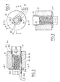
- a hub 10 of a flywheel not shown as a whole is intended to be joined to the end piece 20 of a shaft of a steering column shown partially.
- This hub 10 and this end piece 20 are intended to be immobilized with respect to each other by means of wedging blocking means 100 of a usual type.
- These wedging blocking means 100 comprise a female cone 101 of the means 100 and a male cone 102 carried by the end piece 20. As intended, these male and female cones are engaged in one another.
- the wedging blocking means 100 are implemented using an axial clamping mechanism 200.
- This axial clamping mechanism of a relatively conventional type, comprises a screw 201 whose threads are intended to come into engagement with the tapping a nut 202 formed inside the end piece 20.
- a washer 203 is interposed between the head of the screw and the face of the hub, as shown.
- the nut 202 is obtained if necessary directly in the bore of the hollow end piece 20; the tapping is done by removal in a manner or by forming as it is conventional.
- a device 30 according to the invention is used.
- this device 30 comprises at least a pair of complementary cooperating longitudinal grooves 31 and tongues 32 intended to be engaged with one another.
- these grooves 31 and tongues 32 each have radial faces 301 and 302, respectively, which are placed opposite one another and which are separated from each other by a certain predetermined clearance as is clearly seen in Fig. 1.
- the device 30 also comprises a toothed sector 33 and at least one housing 34 placed opposite the latter.
- This housing 34 is intended to serve as a half-bearing and to receive a pinion 35 capable of meshing with the toothed sector 33.
- the grooves 31 and tongues 32 appear for example in a succession of grooves and protuberances which are obtained for example by deformation of the end piece 20.
- the grooves and complementary tongues of the hub 10 are obtained for example by machining or by molding, as it is classic.
- the grooves and tongues preferably have a polygonal configuration and are for example three in number, so as to present an approximately isosceles triangle configuration.
- the housing 34 is placed immediately between the two successive or contiguous protuberances or tongues 32 forming the base of the isosceles triangle or a side of any other polygonal configuration.
- the housing 34 has a confi guration at most semi-cylindrical.
- the pinion 35 is removable.
- this pinion is formed or secured in any suitable conventional manner, for example by welding to the end of a tool such as a wrench 350, for example bent as shown in particular in FIG. 2.
- the washer 203 is provided with a clearance 204 which allows the pinion 35 to be inserted into its housing 34 in order to make it mesh with the toothed sector 33.
- the device according to the invention can comprise a single pair of groove and tongue.
- the housing is then formed directly in the tongue; it will be observed however that one can also operate in the same way when there is more than one tab.
- the target 201 is not tight and was simply approached so that the male and female cones 101, 102 are not trapped.
- a keying device ensures the correct initial orientation of the washer to facilitate the insertion of the pinion. It is therefore understood that by rotating the right or left key is rotated relatively to each other the hub and the end piece causing their angular offset. This angular offset is allowed within the limit of the stroke which the clearance determined between the radial faces facing 301 and 302 of the grooves and tongues allows.
- the angular travel chosen is of the order of 9 °; it is at least approximately equal to the pitch of the grooves if there are any.
- the device according to the invention also provides security.
- the invention makes it possible to ensure a fine angular relative adjustment of the hub relative to the end piece and by limiting the amplitude of the possible circumferential stroke it also ensures safety while retaining an easy and use complex additional parts.
Landscapes
- Engineering & Computer Science (AREA)
- Mechanical Engineering (AREA)
- General Engineering & Computer Science (AREA)
- Chemical & Material Sciences (AREA)
- Combustion & Propulsion (AREA)
- Transportation (AREA)
- Steering Controls (AREA)
- Gears, Cams (AREA)
Applications Claiming Priority (2)
| Application Number | Priority Date | Filing Date | Title |
|---|---|---|---|
| FR8803985A FR2629035B1 (fr) | 1988-03-25 | 1988-03-25 | Dispositif pour le reglage angulaire progressif du calage d'un volant sur un arbre avec limitation de course |
| FR8803985 | 1988-03-25 |
Publications (2)
| Publication Number | Publication Date |
|---|---|
| EP0334718A1 true EP0334718A1 (de) | 1989-09-27 |
| EP0334718B1 EP0334718B1 (de) | 1991-06-05 |
Family
ID=9364671
Family Applications (1)
| Application Number | Title | Priority Date | Filing Date |
|---|---|---|---|
| EP89400708A Expired - Lifetime EP0334718B1 (de) | 1988-03-25 | 1989-03-14 | Vorrichtung für die Ausrichtung eines Lenkrades auf eine Welle mit Anschlag |
Country Status (7)
| Country | Link |
|---|---|
| US (1) | US4916971A (de) |
| EP (1) | EP0334718B1 (de) |
| JP (1) | JP2812979B2 (de) |
| AU (1) | AU601321B2 (de) |
| DE (1) | DE68900101D1 (de) |
| ES (1) | ES2023526B3 (de) |
| FR (1) | FR2629035B1 (de) |
Cited By (1)
| Publication number | Priority date | Publication date | Assignee | Title |
|---|---|---|---|---|
| CN105114478A (zh) * | 2015-09-21 | 2015-12-02 | 北京临近空间飞行器系统工程研究所 | 一种基于楔键连接的组合式转轴结构 |
Families Citing this family (3)
| Publication number | Priority date | Publication date | Assignee | Title |
|---|---|---|---|---|
| US5265487A (en) * | 1992-09-03 | 1993-11-30 | Ford Motor Company | Apparatus for indexing a rack and pinion mechanism |
| US5855451A (en) * | 1997-04-21 | 1999-01-05 | General Motors Corporation | Coupling between steering wheel and steering shaft |
| US7174784B2 (en) * | 2004-01-15 | 2007-02-13 | Delaware Capital Formation, Inc. | Apparatus for measuring a fluid level and methods |
Citations (2)
| Publication number | Priority date | Publication date | Assignee | Title |
|---|---|---|---|---|
| DE1094610B (de) * | 1956-03-08 | 1960-12-08 | Petri Lenkradwerk | Abnehmbares Lenkrad fuer Kraftfahrzeuge |
| FR2557992A1 (fr) * | 1984-01-06 | 1985-07-12 | Eckendorff Jean Pierre | Dispositif pour regler la position angulaire d'un organe cale en rotation avec un arbre, notamment volant de vehicule automobile associe a une colonne de direction. |
Family Cites Families (11)
| Publication number | Priority date | Publication date | Assignee | Title |
|---|---|---|---|---|
| GB190121618A (en) * | 1901-10-28 | 1902-10-16 | Heinrich Wilhelm Schlotfeldt | Improvements relating to Rotary Speed Indicators. |
| GB191223A (en) * | 1921-11-08 | 1923-01-11 | Armand Lorand | Improvements in keying devices for securing wheels, coupling sleeves, arms, brackets, and other articles upon shafts or shafting, or rods, spindles or the like |
| GB221060A (en) * | 1923-07-30 | 1924-09-04 | Alfred Ernest Bersey | Improvements in and relating to steering wheels of motor and like vehicles |
| FR986776A (fr) * | 1949-03-18 | 1951-08-06 | Perfectionnements aux volants de direction, notamment pour automobiles | |
| FR2527156B1 (fr) * | 1982-05-18 | 1986-11-14 | Renault | Dispositif d'assemblage d'un moyeu de volant sur un arbre |
| DE3400609A1 (de) * | 1983-08-06 | 1985-02-14 | Volkswagenwerk Ag, 3180 Wolfsburg | Anordnung zur befestigung der lenkradnabe auf einer lenksaeule |
| FR2592925B1 (fr) * | 1986-01-13 | 1989-07-13 | Peugeot Aciers Et Outillage | Dispositif de reglage de la position angulaire d'un organe comportant un moyeu sur un arbre, notamment d'un volant de direction sur un arbre de direction de vehicule automobile. |
| CA1271112A (en) * | 1986-01-14 | 1990-07-03 | Nihon Plast Co., Ltd. | Steering wheel |
| FR2594086B1 (fr) * | 1986-02-10 | 1988-05-27 | Peugeot Aciers Et Outillage | Dispositif de reglage perfectionne de la position angulaire d'un organe sur un arbre, notamment d'un volant sur un arbre de direction |
| FR2615468B1 (fr) * | 1987-05-19 | 1989-08-18 | Nacam | Dispositif d'accouplement d'un volant a son arbre et son application au calage d'un volant de direction d'automobile |
| FR2616399B1 (fr) * | 1987-12-09 | 1989-10-20 | Ecia Equip Composants Ind Auto | Dispositif pour assurer le reglage fin du calage de l'orientation angulaire d'un volant sur un arbre de direction d'automobile |
-
1988
- 1988-03-25 FR FR8803985A patent/FR2629035B1/fr not_active Expired - Lifetime
-
1989
- 1989-03-14 DE DE8989400708T patent/DE68900101D1/de not_active Expired - Lifetime
- 1989-03-14 ES ES89400708T patent/ES2023526B3/es not_active Expired - Lifetime
- 1989-03-14 EP EP89400708A patent/EP0334718B1/de not_active Expired - Lifetime
- 1989-03-21 AU AU31590/89A patent/AU601321B2/en not_active Ceased
- 1989-03-23 US US07/327,774 patent/US4916971A/en not_active Expired - Lifetime
- 1989-03-27 JP JP1074774A patent/JP2812979B2/ja not_active Expired - Lifetime
Patent Citations (2)
| Publication number | Priority date | Publication date | Assignee | Title |
|---|---|---|---|---|
| DE1094610B (de) * | 1956-03-08 | 1960-12-08 | Petri Lenkradwerk | Abnehmbares Lenkrad fuer Kraftfahrzeuge |
| FR2557992A1 (fr) * | 1984-01-06 | 1985-07-12 | Eckendorff Jean Pierre | Dispositif pour regler la position angulaire d'un organe cale en rotation avec un arbre, notamment volant de vehicule automobile associe a une colonne de direction. |
Cited By (1)
| Publication number | Priority date | Publication date | Assignee | Title |
|---|---|---|---|---|
| CN105114478A (zh) * | 2015-09-21 | 2015-12-02 | 北京临近空间飞行器系统工程研究所 | 一种基于楔键连接的组合式转轴结构 |
Also Published As
| Publication number | Publication date |
|---|---|
| EP0334718B1 (de) | 1991-06-05 |
| JP2812979B2 (ja) | 1998-10-22 |
| JPH0214970A (ja) | 1990-01-18 |
| FR2629035B1 (fr) | 1990-12-28 |
| US4916971A (en) | 1990-04-17 |
| AU601321B2 (en) | 1990-09-06 |
| ES2023526B3 (es) | 1992-01-16 |
| AU3159089A (en) | 1989-09-28 |
| DE68900101D1 (de) | 1991-07-11 |
| FR2629035A1 (fr) | 1989-09-29 |
Similar Documents
| Publication | Publication Date | Title |
|---|---|---|
| EP0148794B1 (de) | Winkelreguliereinrichtung eines getriebenen Drehelementes, an ein getriebenes Drehelement gekuppelt | |
| EP0320333B1 (de) | Vorrichtung zur Sicherstellung der Feineinstellung der Winkellage eines Lenkrades auf einer Lenksäule | |
| EP2024219B1 (de) | System zur arretierung eines schafts in einer bestimmten lage im verhältnis zu einem anderen schaft unter eliminierung des spielraums zwischen den beiden schäften | |
| FR2561327A1 (fr) | Ecrou autoserreur devissable | |
| FR2688554A1 (fr) | Dispositif et procede de fixation d'un moyeu sur un bout d'arbre. | |
| EP0281442B1 (de) | Einstellvorrichtung des Winkelstandes eines Lenkrades auf einer Fahrzeuglenksäule | |
| FR2975455A1 (fr) | Unite de synchronisation d'une boite de vitesses | |
| WO2004007252A2 (fr) | Dispositif de blocage à fonction antivol pour véhicule automobile à direction assistée électrique | |
| EP0334718B1 (de) | Vorrichtung für die Ausrichtung eines Lenkrades auf eine Welle mit Anschlag | |
| FR2963398A1 (fr) | Transmission planetaire comportant une roue solaire et un porte-satellites | |
| EP0292358B1 (de) | Vorrichtung zum Verbinden eines Lenkrades mit der Lenksäule und ihre Verwendung bei der Befestigung eines Autolenkrades | |
| FR2544811A1 (fr) | Ecrou pour la fixation d'une roue de vehicule industriel | |
| EP2330319B1 (de) | Reduziergetriebe mit Schnecke und Schneckenrad und deren Verwendung in einem elektrischen Servolenkungssystem | |
| FR3059741B1 (fr) | "dispositif de couplage a crabot pour une boite de vitesses de vehicule automobile" | |
| EP0800978A1 (de) | Stossenergieaufnehmende Lenksäuleneinrichtung,insbesondere für ein Kraftfahrzeug | |
| US7758463B2 (en) | Power transmitting apparatus | |
| WO2010052003A1 (fr) | Module mecanique pour une cle d'un vehicule et procede de fabrication | |
| FR2771060A1 (fr) | Antivol pour un arbre de colonne de direction de vehicule automobile | |
| FR2673691A1 (fr) | Dispositif d'accouplement mecanique separable. | |
| FR1259898A (fr) | Dispositif d'entraînement et de freinage pour moyeux à roue libre | |
| FR2751605A1 (fr) | Dispositif de fixation d'un moyeu de volant de direction de vehicule, sur une extremite d'un arbre de direction | |
| WO1989012179A1 (fr) | Systeme d'assemblage d'un element menant accouple a un element mene | |
| WO2024251838A1 (fr) | Dispositif de blocage d'une transmission de chaîne cinématique dans un véhicule automobile | |
| FR2489452A1 (fr) | Joint homocinetique | |
| TWM635554U (zh) | 手把鏡調整結構改良 |
Legal Events
| Date | Code | Title | Description |
|---|---|---|---|
| PUAI | Public reference made under article 153(3) epc to a published international application that has entered the european phase |
Free format text: ORIGINAL CODE: 0009012 |
|
| AK | Designated contracting states |
Kind code of ref document: A1 Designated state(s): BE DE ES GB IT NL SE |
|
| 17P | Request for examination filed |
Effective date: 19891005 |
|
| 17Q | First examination report despatched |
Effective date: 19901002 |
|
| GRAA | (expected) grant |
Free format text: ORIGINAL CODE: 0009210 |
|
| AK | Designated contracting states |
Kind code of ref document: B1 Designated state(s): BE DE ES GB IT NL SE |
|
| ITF | It: translation for a ep patent filed | ||
| REF | Corresponds to: |
Ref document number: 68900101 Country of ref document: DE Date of ref document: 19910711 |
|
| RAP2 | Party data changed (patent owner data changed or rights of a patent transferred) |
Owner name: NACAM |
|
| GBT | Gb: translation of ep patent filed (gb section 77(6)(a)/1977) | ||
| BECN | Be: change of holder's name |
Effective date: 19910605 |
|
| REG | Reference to a national code |
Ref country code: ES Ref legal event code: FG2A Ref document number: 2023526 Country of ref document: ES Kind code of ref document: B3 |
|
| PLBE | No opposition filed within time limit |
Free format text: ORIGINAL CODE: 0009261 |
|
| STAA | Information on the status of an ep patent application or granted ep patent |
Free format text: STATUS: NO OPPOSITION FILED WITHIN TIME LIMIT |
|
| 26N | No opposition filed | ||
| PGFP | Annual fee paid to national office [announced via postgrant information from national office to epo] |
Ref country code: SE Payment date: 19940228 Year of fee payment: 6 |
|
| PGFP | Annual fee paid to national office [announced via postgrant information from national office to epo] |
Ref country code: NL Payment date: 19940331 Year of fee payment: 6 Ref country code: BE Payment date: 19940331 Year of fee payment: 6 |
|
| REG | Reference to a national code |
Ref country code: GB Ref legal event code: 746 Effective date: 19940808 |
|
| EAL | Se: european patent in force in sweden |
Ref document number: 89400708.7 |
|
| PG25 | Lapsed in a contracting state [announced via postgrant information from national office to epo] |
Ref country code: SE Effective date: 19950315 |
|
| PG25 | Lapsed in a contracting state [announced via postgrant information from national office to epo] |
Ref country code: BE Effective date: 19950331 |
|
| BERE | Be: lapsed |
Owner name: NACAM Effective date: 19950331 |
|
| PG25 | Lapsed in a contracting state [announced via postgrant information from national office to epo] |
Ref country code: NL Effective date: 19951001 |
|
| NLV4 | Nl: lapsed or anulled due to non-payment of the annual fee |
Effective date: 19951001 |
|
| EUG | Se: european patent has lapsed |
Ref document number: 89400708.7 |
|
| PGFP | Annual fee paid to national office [announced via postgrant information from national office to epo] |
Ref country code: ES Payment date: 20010212 Year of fee payment: 13 |
|
| PGFP | Annual fee paid to national office [announced via postgrant information from national office to epo] |
Ref country code: DE Payment date: 20010228 Year of fee payment: 13 |
|
| PGFP | Annual fee paid to national office [announced via postgrant information from national office to epo] |
Ref country code: GB Payment date: 20010308 Year of fee payment: 13 |
|
| REG | Reference to a national code |
Ref country code: GB Ref legal event code: IF02 |
|
| PG25 | Lapsed in a contracting state [announced via postgrant information from national office to epo] |
Ref country code: GB Free format text: LAPSE BECAUSE OF NON-PAYMENT OF DUE FEES Effective date: 20020314 |
|
| PG25 | Lapsed in a contracting state [announced via postgrant information from national office to epo] |
Ref country code: ES Free format text: LAPSE BECAUSE OF NON-PAYMENT OF DUE FEES Effective date: 20020315 |
|
| PG25 | Lapsed in a contracting state [announced via postgrant information from national office to epo] |
Ref country code: DE Free format text: LAPSE BECAUSE OF NON-PAYMENT OF DUE FEES Effective date: 20021001 |
|
| GBPC | Gb: european patent ceased through non-payment of renewal fee |
Effective date: 20020314 |
|
| REG | Reference to a national code |
Ref country code: ES Ref legal event code: FD2A Effective date: 20030410 |
|
| PG25 | Lapsed in a contracting state [announced via postgrant information from national office to epo] |
Ref country code: IT Free format text: LAPSE BECAUSE OF NON-PAYMENT OF DUE FEES;WARNING: LAPSES OF ITALIAN PATENTS WITH EFFECTIVE DATE BEFORE 2007 MAY HAVE OCCURRED AT ANY TIME BEFORE 2007. THE CORRECT EFFECTIVE DATE MAY BE DIFFERENT FROM THE ONE RECORDED. Effective date: 20050314 |