EP0334366A2 - Automatic guided vehicle roll-handling system - Google Patents
Automatic guided vehicle roll-handling system Download PDFInfo
- Publication number
- EP0334366A2 EP0334366A2 EP89105266A EP89105266A EP0334366A2 EP 0334366 A2 EP0334366 A2 EP 0334366A2 EP 89105266 A EP89105266 A EP 89105266A EP 89105266 A EP89105266 A EP 89105266A EP 0334366 A2 EP0334366 A2 EP 0334366A2
- Authority
- EP
- European Patent Office
- Prior art keywords
- roll
- vehicle
- arms
- rack
- paper
- Prior art date
- Legal status (The legal status is an assumption and is not a legal conclusion. Google has not performed a legal analysis and makes no representation as to the accuracy of the status listed.)
- Withdrawn
Links
Images
Classifications
-
- B—PERFORMING OPERATIONS; TRANSPORTING
- B65—CONVEYING; PACKING; STORING; HANDLING THIN OR FILAMENTARY MATERIAL
- B65H—HANDLING THIN OR FILAMENTARY MATERIAL, e.g. SHEETS, WEBS, CABLES
- B65H19/00—Changing the web roll
- B65H19/22—Changing the web roll in winding mechanisms or in connection with winding operations
- B65H19/30—Lifting, transporting, or removing the web roll; Inserting core
-
- B—PERFORMING OPERATIONS; TRANSPORTING
- B65—CONVEYING; PACKING; STORING; HANDLING THIN OR FILAMENTARY MATERIAL
- B65H—HANDLING THIN OR FILAMENTARY MATERIAL, e.g. SHEETS, WEBS, CABLES
- B65H19/00—Changing the web roll
- B65H19/10—Changing the web roll in unwinding mechanisms or in connection with unwinding operations
- B65H19/12—Lifting, transporting, or inserting the web roll; Removing empty core
- B65H19/126—Lifting, transporting, or inserting the web roll; Removing empty core with both-ends supporting arrangements
-
- B—PERFORMING OPERATIONS; TRANSPORTING
- B65—CONVEYING; PACKING; STORING; HANDLING THIN OR FILAMENTARY MATERIAL
- B65H—HANDLING THIN OR FILAMENTARY MATERIAL, e.g. SHEETS, WEBS, CABLES
- B65H2301/00—Handling processes for sheets or webs
- B65H2301/40—Type of handling process
- B65H2301/41—Winding, unwinding
- B65H2301/415—Unwinding
- B65H2301/41505—Preparing unwinding process
- B65H2301/41506—Preparing unwinding process the web roll not yet being in the unwinding support / unwinding location
- B65H2301/415063—Preparing unwinding process the web roll not yet being in the unwinding support / unwinding location the preparation performed in a roll preparation station
-
- B—PERFORMING OPERATIONS; TRANSPORTING
- B65—CONVEYING; PACKING; STORING; HANDLING THIN OR FILAMENTARY MATERIAL
- B65H—HANDLING THIN OR FILAMENTARY MATERIAL, e.g. SHEETS, WEBS, CABLES
- B65H2301/00—Handling processes for sheets or webs
- B65H2301/40—Type of handling process
- B65H2301/41—Winding, unwinding
- B65H2301/417—Handling or changing web rolls
- B65H2301/41702—Handling or changing web rolls management and organisation of stock and production
-
- B—PERFORMING OPERATIONS; TRANSPORTING
- B65—CONVEYING; PACKING; STORING; HANDLING THIN OR FILAMENTARY MATERIAL
- B65H—HANDLING THIN OR FILAMENTARY MATERIAL, e.g. SHEETS, WEBS, CABLES
- B65H2301/00—Handling processes for sheets or webs
- B65H2301/40—Type of handling process
- B65H2301/41—Winding, unwinding
- B65H2301/417—Handling or changing web rolls
- B65H2301/4171—Handling web roll
- B65H2301/4172—Handling web roll by circumferential portion, e.g. rolling on circumference
-
- B—PERFORMING OPERATIONS; TRANSPORTING
- B65—CONVEYING; PACKING; STORING; HANDLING THIN OR FILAMENTARY MATERIAL
- B65H—HANDLING THIN OR FILAMENTARY MATERIAL, e.g. SHEETS, WEBS, CABLES
- B65H2301/00—Handling processes for sheets or webs
- B65H2301/40—Type of handling process
- B65H2301/41—Winding, unwinding
- B65H2301/417—Handling or changing web rolls
- B65H2301/4171—Handling web roll
- B65H2301/41745—Handling web roll by axial movement of roll
-
- B—PERFORMING OPERATIONS; TRANSPORTING
- B65—CONVEYING; PACKING; STORING; HANDLING THIN OR FILAMENTARY MATERIAL
- B65H—HANDLING THIN OR FILAMENTARY MATERIAL, e.g. SHEETS, WEBS, CABLES
- B65H2405/00—Parts for holding the handled material
- B65H2405/40—Holders, supports for rolls
- B65H2405/42—Supports for rolls fully removable from the handling machine
- B65H2405/422—Trolley, cart, i.e. support movable on floor
-
- Y—GENERAL TAGGING OF NEW TECHNOLOGICAL DEVELOPMENTS; GENERAL TAGGING OF CROSS-SECTIONAL TECHNOLOGIES SPANNING OVER SEVERAL SECTIONS OF THE IPC; TECHNICAL SUBJECTS COVERED BY FORMER USPC CROSS-REFERENCE ART COLLECTIONS [XRACs] AND DIGESTS
- Y10—TECHNICAL SUBJECTS COVERED BY FORMER USPC
- Y10S—TECHNICAL SUBJECTS COVERED BY FORMER USPC CROSS-REFERENCE ART COLLECTIONS [XRACs] AND DIGESTS
- Y10S414/00—Material or article handling
- Y10S414/124—Roll handlers
Definitions
- This invention relates to automatic apparatus for handling paper rolls and particularly for furnishing each web reel of a rotary printing press with a new web or roll of paper.
- Printing presses require rolls of paper in large quantities. Generally there are several presses along a printing line, with each press carrying one or more rolls of paper on a reel. The reel is provided with spindles that engage the center core of the paper roll.
- the paper rolls are stored in a warehouse and delivered to laydown areas adjacent the printing presses.
- the control of paper storage time in the laydown area is important as some paper, if stored for too long a time, will yellow or deteriorate and not be suitable for high quality printing.
- the yellowed roll may be used for lower quality printing.
- the conventional technique for handling rolls for delivery to the printing presses is through the use of a conventional forklift truck.
- the truck has two forwardly protruding forks which lift the roll by placing the forks beneath the lower peripheral surface of the roll, lifting the roll off its support, and delivering the roll to another support or to a printing press transfer cart.
- a disadvantage with the conventional forklift truck is that it must be moved into and then reversed out of the storage racks. As a result, the handling of the rolls with a forklift and their selection for delivery to the laydown area, removal from the laydown area, and delivery to the printing press is greatly limited.
- Another difficulty associated with delivering rolls to the printing press is that the positioning of the paper roll at the press location has conventionally been accomplished by placing the roll on a transfer cart. The transfer cart is then manually positioned beneath an empty spindle at a printing press for transfer of the paper roll to the spindle.
- U.S. Patent No. 4,131,206 One approach to automating the transfer of the roll to the spindle of the printing press is shown in U.S. Patent No. 4,131,206.
- a paper roll is delivered on a first truck to the vicinity of the printing press spindle, where it is rolled onto a second truck.
- the second truck can lift the first truck and move it horizontally to position the roll on the first truck into alignment with the spindle of the paper press.
- a low-profile vehicle having an automatically controllable guidance system and a vertically extendable roll support cradle.
- the roll support cradle advantageously can carry a roll on its peripheral surface, with the lengthwise axis of the roll being horizontal, or the cradle can carry the roll on its bottom surface, with the lengthwise axis of the roll being vertical.
- a position of the roll with its lengthwise axis being horizontal will be called a "bilge” position.
- a position of the roll with its lengthwise axis being vertical will be called an "on-end" or "upright” position.
- the automatic guided vehicle is used in combination with racks having roll supporting bars which have a vertical height greater than the height of the vehicle with the roll support cradle retracted, but of a height capable of allowing the roll support cradle to extend above the support bars.
- the vehicle can pass beneath rolls on the rack to selectively lift either a forwardmost or rearwardmost roll from a plurality of rolls on a rack.
- the vehicle can pass beneath the racks in a standard single direction, if desired, which is preferable so that the vehicle starts at the rearmost roll of the rack, passes beneath that roll and other rolls on the rack, and lifts the forwardmost roll from the rack for delivery to the printing press.
- This system advantageously allows use of a method by which the first roll placed into a laydown area or temporary storage can be the first roll out. Similarly the second roll in a row of rolls can then become the second roll out and so on.
- This type of method assures that no roll of paper need be stored at the laydown area for too long a period merely because the transfer vehicle cannot access the rolls that were first delivered to that laydown area.
- the method also advanta geously allows the vehicle to travel in a single direction beneath the laydown racks, making coordinating and operation of multiple vehicles in the storage area and press area much easier to control without vehicles colliding or being held up because of interference with another vehicle in the system.
- the unidirectional movement of the vehicle is also easier for control operations, making it easier to lay out the plant and determine the timing of movement of the various vehicles in the system.
- Another feature of the invention is a transfer table for moving a paper roll into the spindle of the paper press after having received the roll from the automatic guided vehicle.
- the transfer table has a pair of spaced, articulated parallel arms which can be raised above the floor.
- the automatic guided vehicle then passes between these arms with the paper roll in the bilge position and elevated above the arms.
- the automatic guided vehicle lowers the roll onto these spaced, parallel arms and then leaves the transfer table by continuing its forward direction out the other end of the transfer table.
- This unidirectional movement reduces the chance of collision or interference with another vehicle that is approaching with a fresh roll to be delivered to that transfer table. It also allows the vehicle to travel on the discharge side of the printing presses while incoming rolls are delivered at the incoming side of the presses without the incoming and leaving vehicles having to interfere with one another on the same path.
- the arms can be elevated, moved lengthwise to the direction of the lengthwise axis of the roll, and moved transverse to the lengthwise direction of the roll for positioning the roll between the chucks of the spindle at the printing press.
- a typical printing press facility has a warehouse WH, temporary storage racks TS, a laydown area LD, and a printing press area P where there are a plurality of presses in tandem.
- each press will be provided with a reel R that has a plurality of spindles S.
- a roll is placed within chucks of the spindles in a storage or make-ready position.
- the next roll on the reel is positioned to be attached to the tail end of the active roll. In this way, by rotation of the reel to position the spindles from a storage position to an active position, empty spindles can be reloaded with fresh rolls of paper so that the press will always have available to it a roll of paper than can immediately be placed into an active condition.
- the warehouse personnel usually store the rolls 10 in their upright position, one on top of the other.
- the rolls can be removed by various forklift or vacuum truck-lift equipment, as is well known in the art.
- the roll gets placed on the temporary storage racks TS.
- an automatic guided vehicle 12 begins its transferring of the rolls.
- the automatic guided vehicle 12 moves the rolls from one of the temporary storage racks by passing beneath the racks to lift a roll off the rack and delivers it to a downender 14.
- the downender is a conventional apparatus having a set of horizontal and vertical legs. The roll is placed on the horizontal legs by the automatic guided vehicle. The legs are then pivoted so that the roll is rotated from its upright position to the bilge position.
- the automatic guided vehicle 12 then moves beneath the roll on the downender and further transports the roll from the downender to one of the laydown racks 16 at the laydown area LD. Finally, the vehicle takes a selected roll from the laydown area and delivers it to a transfer location at a particular printing press. The vehicle enters from one side of the press, delivers its load or roll onto a transfer table at the printing press, and passes outwardly through the other side of the printing press to return to another area in the printing press facility.
- the vehicle can merely deliver the roll to a conventional transfer cart at one of the printing presses and leave the area without passing through the printing press.
- the roll is then manually propelled into position beneath the spindle at that particular press.
- the automatically guided vehicle 12 is best shown in Figures 2 and 3 and includes a low-profile chassis 20 carried along the ground by a conventional automatic guidance system 21 that controls a steerable forward wheel 23.
- a rear set of wheels 22 supports the rear end of the vehicle.
- the vehicle is powered for motion both in the forward and rearward direction.
- the vehicle is generally guided by a wire which is embedded into the concrete of the floor of the printing press facility. Guided vehicles having propulsion, steerage, and guidance are well known and the details of these mechanisms are not necessary for an understanding of this invention.
- chassis 20 is of a low profile sufficient to fit beneath storage racks 16 and has an levatable cradle 24 for lifting a roll above the height of the racks 16.
- a typical rack 16 is shown having a vertical leg 25 and a horizontal leg 26.
- a roll 10 can be in the upright position, as shown at 10u, or can be supported on the rack in the bilge position, as shown at 10b.
- the cradle 22 has a recess 28 for cradling the roll in its bilge position so that the roll will not roll off the cradle.
- the cradle also has a flat upper surface 30 to carry an upright roll, as shown in the double-dot, phantom line position with reference to numeral 10u.
- a cradle lifting mechanism 32 and a cradle guiding mechanism 34 are best shown schematically in Figures 3 and 4.
- the cradle guiding mechanism 34 includes a pair of bottom links 36 and 37 which are fixed to a common shaft 38.
- the links 36 and 37 are pivotally connected to upper links 39 and 40, respectively.
- the links guide the cradle as it is moved vertically, keeping it from tipping fore and aft and cam rolls 41 guide the cradle keeping it from tipping transverse to the lengthwise axis of the roll.
- the jack mechanism includes a motor 50 which rotates a worm 51.
- the worm 51 meshes with and rotates a worm wheel 52.
- the worm wheel 52 is also internally threaded and meshes with a nonrotatable screw 54.
- the upper end of the screw is attached to the cradle 24. Rotation of the worm 51 rotates the worm wheel 52, which in turn causes the nonrotatable screw to thread its way up or down in the worm wheel 52.
- the cradle thus travels up or down with the upper end of the screw.
- a preferred automatic guided vehicle 12 will be fully automatic, capable of carrying at least 4,000 pounds, capable of handling rolls up to 50 ⁇ or more in diameter and up to 55 ⁇ or more in length.
- a typical speed of operation will be approximately 200 feet per minute.
- the transfer table is best shown in Figures 5-8 and includes a base 60 mounted on wheels 62 that run in tracks 63.
- the tracks 63 are positioned at right angles to the lengthwise axis of the roll in its bilge position within a reel R for movement of a roll horizontally toward or away from the spindles of a reel.
- the wheels are propelled by a conventional motor 64, shown schematically, the details of which are not necessary to an understanding of the invention.
- a horizontal central platform 66 and two side platforms 68 Fixed to the top of the base are a horizontal central platform 66 and two side platforms 68. Mounted above these platforms are a pair of articulated arms 70, only one of which will be described. It should be understood that the opposite arm is identical and articulated in a similar fashion.
- the arm 70 is pivotally mounted on a horizontal pivot shaft 72. In the lowered position, as shown in solid lines in Figure 5, the arm forms an extension of the platform and serves as a working surface for a workman who is preparing a roll on a reel.
- the arm is pivoted by a conventional air bag tilt mechanism 74 ( Figure 8).
- the arm is locked in place by an over-center linkage 76 ( Figure 7) that is actuated by a pneumatic cylinder and piston 80.
- the linkage When the linkage is fully retracted to its over-center position, the arm cannot be lowered under the weight of a heavy roll.
- the arms can also be raised vertically by sets of cylinders and pistons 84 ( Figures 5 and 6) which move the arms, pivot mechanism, air bags, and over-centering locking mechanisms together as a unit.
- the arms can also be moved lengthwise in the direction of the lengthwise axis of a roll by a carriage 88 which is guided in its lengthwise movement by guide rollers 89 moving in tracks 90.
- the carriage is supported on the tracks by rollers 94, which rotate about horizontal axes.
- An air-powered centering piston and cylinder 96 positions the carriage along the tracks 90.
- the tracks 90 form part of a framework 99 that is lifted by the piston rods of the piston-cylinders 84.
- the cylinders 84 are mounted on the base 60.
- the arms 70 will be elevated and the automatically guided vehicle driven 12 beneath the arms.
- the cradle on the automatically guided vehicle will be lowered to lower the roll onto the upper ends of the arms 70.
- the entire transfer table can then be moved on the tracks 63 perpendicular to the lengthwise axis of the roll between the chucks of a spindle.
- the roll can be further positioned along its lengthwise axis by the carriage 88 and can be elevated or lowered by the piston and cylinders 84.
- the invention advantageously provides apparatus and methods for enhancing the delivery of paper rolls to a plurality of printing presses.
- the invention also illustrates and describes a unique transfer table positionable at the printing press for delivering the roll from the automatically guided vehicle to the reel of a printing press. While the preferred embodiments of the invention have been illustrated and described, it should be apparent that variations will be apparent to one of ordinary skill in the art. Accordingly, the invention is not to be limited to the embodiments illustrated in the drawings.
Landscapes
- Replacement Of Web Rolls (AREA)
- Warehouses Or Storage Devices (AREA)
- Intermediate Stations On Conveyors (AREA)
Abstract
Description
- This invention relates to automatic apparatus for handling paper rolls and particularly for furnishing each web reel of a rotary printing press with a new web or roll of paper.
- Printing presses require rolls of paper in large quantities. Generally there are several presses along a printing line, with each press carrying one or more rolls of paper on a reel. The reel is provided with spindles that engage the center core of the paper roll.
- The paper rolls are stored in a warehouse and delivered to laydown areas adjacent the printing presses. The control of paper storage time in the laydown area is important as some paper, if stored for too long a time, will yellow or deteriorate and not be suitable for high quality printing. The yellowed roll may be used for lower quality printing.
- The storing and delivery of the rolls to the laydown area, and the delivery of the rolls from the laydown area to the spindle of the printing press, require a large amount of equipment and expense for a printing company such as a newspaper publishing company.
- The conventional technique for handling rolls for delivery to the printing presses is through the use of a conventional forklift truck. The truck has two forwardly protruding forks which lift the roll by placing the forks beneath the lower peripheral surface of the roll, lifting the roll off its support, and delivering the roll to another support or to a printing press transfer cart. A disadvantage with the conventional forklift truck is that it must be moved into and then reversed out of the storage racks. As a result, the handling of the rolls with a forklift and their selection for delivery to the laydown area, removal from the laydown area, and delivery to the printing press is greatly limited.
- Another difficulty associated with delivering rolls to the printing press is that the positioning of the paper roll at the press location has conventionally been accomplished by placing the roll on a transfer cart. The transfer cart is then manually positioned beneath an empty spindle at a printing press for transfer of the paper roll to the spindle.
- One approach to automating the transfer of the roll to the spindle of the printing press is shown in U.S. Patent No. 4,131,206. In this patent, a paper roll is delivered on a first truck to the vicinity of the printing press spindle, where it is rolled onto a second truck. The second truck can lift the first truck and move it horizontally to position the roll on the first truck into alignment with the spindle of the paper press.
- It is an object of this invention to provide an automatic guided vehicle system for handling paper rolls at a printing press facility by supporting the rolls on a low- profile vehicle that can travel beneath rolls previously stored on aboveground storage racks.
- It is another object of this invention to provide a method of handling paper rolls by positioning a vehicle entirely beneath a paper roll, lifting the roll and automatically guiding the roll to a storage rack capable of holding at least two paper rolls, guiding the vehicle beneath the rack while lifting the roll above the rack, and lowering the roll onto the rack, and in which the vehicle can pass beneath rolls already existing on the rack, either after delivery of a roll onto the rack or to access one of the end rolls at either end of the rack.
- Basically these objects are obtained by providing a low-profile vehicle having an automatically controllable guidance system and a vertically extendable roll support cradle. The roll support cradle advantageously can carry a roll on its peripheral surface, with the lengthwise axis of the roll being horizontal, or the cradle can carry the roll on its bottom surface, with the lengthwise axis of the roll being vertical. A position of the roll with its lengthwise axis being horizontal will be called a "bilge" position. A position of the roll with its lengthwise axis being vertical will be called an "on-end" or "upright" position.
- The automatic guided vehicle is used in combination with racks having roll supporting bars which have a vertical height greater than the height of the vehicle with the roll support cradle retracted, but of a height capable of allowing the roll support cradle to extend above the support bars. In this manner, the vehicle can pass beneath rolls on the rack to selectively lift either a forwardmost or rearwardmost roll from a plurality of rolls on a rack. The vehicle can pass beneath the racks in a standard single direction, if desired, which is preferable so that the vehicle starts at the rearmost roll of the rack, passes beneath that roll and other rolls on the rack, and lifts the forwardmost roll from the rack for delivery to the printing press.
- This system advantageously allows use of a method by which the first roll placed into a laydown area or temporary storage can be the first roll out. Similarly the second roll in a row of rolls can then become the second roll out and so on. This type of method assures that no roll of paper need be stored at the laydown area for too long a period merely because the transfer vehicle cannot access the rolls that were first delivered to that laydown area. The method also advanta geously allows the vehicle to travel in a single direction beneath the laydown racks, making coordinating and operation of multiple vehicles in the storage area and press area much easier to control without vehicles colliding or being held up because of interference with another vehicle in the system. The unidirectional movement of the vehicle is also easier for control operations, making it easier to lay out the plant and determine the timing of movement of the various vehicles in the system.
- Another feature of the invention is a transfer table for moving a paper roll into the spindle of the paper press after having received the roll from the automatic guided vehicle. The transfer table has a pair of spaced, articulated parallel arms which can be raised above the floor. The automatic guided vehicle then passes between these arms with the paper roll in the bilge position and elevated above the arms. The automatic guided vehicle lowers the roll onto these spaced, parallel arms and then leaves the transfer table by continuing its forward direction out the other end of the transfer table. This unidirectional movement reduces the chance of collision or interference with another vehicle that is approaching with a fresh roll to be delivered to that transfer table. It also allows the vehicle to travel on the discharge side of the printing presses while incoming rolls are delivered at the incoming side of the presses without the incoming and leaving vehicles having to interfere with one another on the same path.
- The arms can be elevated, moved lengthwise to the direction of the lengthwise axis of the roll, and moved transverse to the lengthwise direction of the roll for positioning the roll between the chucks of the spindle at the printing press.
-
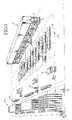
- Figure 1 is a schematic of an overall layout of a warehouse, laydown or temporary storage area, and printing press location.
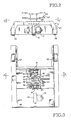
- Figure 2 is a fragmentary end elevation showing a typical automatic guided vehicle of this invention.
- Figure 3 is a fragmentary horizontal section taken along the line 3-3 of Figure 2.
- Figure 4 is a fragmentary vertical section of a transfer table embodying the principles of the invention and taken along lines 4-4 of Figure 3.
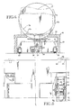
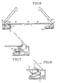
- Figure 5 is a plan view of one-half of a transfer table embodying principles of the invention.
- Figure 6 is a fragmentary vertical section taken along the line 6-6 of Figure 5.
- Figure 7 is a fragmentary vertical section taken along the line 7-7 of Figure 5.
- Figure 8 is a fragmentary vertical section taken along the line 8-8 of Figure 5.
- As best shown in Figure 1, a typical printing press facility has a warehouse WH, temporary storage racks TS, a laydown area LD, and a printing press area P where there are a plurality of presses in tandem.
- At the printing press area P, each press will be provided with a reel R that has a plurality of spindles S. A roll is placed within chucks of the spindles in a storage or make-ready position. When the press is about to use up the roll then being actively fed to the printers, the next roll on the reel is positioned to be attached to the tail end of the active roll. In this way, by rotation of the reel to position the spindles from a storage position to an active position, empty spindles can be reloaded with fresh rolls of paper so that the press will always have available to it a roll of paper than can immediately be placed into an active condition.
- The warehouse personnel usually store the rolls 10 in their upright position, one on top of the other. The rolls can be removed by various forklift or vacuum truck-lift equipment, as is well known in the art. The roll gets placed on the temporary storage racks TS.
- At the temporary storage location TS, an automatic guided
vehicle 12 begins its transferring of the rolls. The automatic guidedvehicle 12 moves the rolls from one of the temporary storage racks by passing beneath the racks to lift a roll off the rack and delivers it to adownender 14. The downender is a conventional apparatus having a set of horizontal and vertical legs. The roll is placed on the horizontal legs by the automatic guided vehicle. The legs are then pivoted so that the roll is rotated from its upright position to the bilge position. - The automatic guided
vehicle 12 then moves beneath the roll on the downender and further transports the roll from the downender to one of the laydown racks 16 at the laydown area LD. Finally, the vehicle takes a selected roll from the laydown area and delivers it to a transfer location at a particular printing press. The vehicle enters from one side of the press, delivers its load or roll onto a transfer table at the printing press, and passes outwardly through the other side of the printing press to return to another area in the printing press facility. - If desired, the vehicle can merely deliver the roll to a conventional transfer cart at one of the printing presses and leave the area without passing through the printing press. The roll is then manually propelled into position beneath the spindle at that particular press.
- The automatically guided
vehicle 12 is best shown in Figures 2 and 3 and includes a low-profile chassis 20 carried along the ground by a conventionalautomatic guidance system 21 that controls a steerableforward wheel 23. A rear set ofwheels 22 supports the rear end of the vehicle. The vehicle is powered for motion both in the forward and rearward direction. The vehicle is generally guided by a wire which is embedded into the concrete of the floor of the printing press facility. Guided vehicles having propulsion, steerage, and guidance are well known and the details of these mechanisms are not necessary for an understanding of this invention. - The important detail of this invention is that the
chassis 20 is of a low profile sufficient to fit beneath storage racks 16 and has anlevatable cradle 24 for lifting a roll above the height of theracks 16. - As best shown in Figure 3, a
typical rack 16 is shown having avertical leg 25 and ahorizontal leg 26. A roll 10 can be in the upright position, as shown at 10u, or can be supported on the rack in the bilge position, as shown at 10b. Thecradle 22 has arecess 28 for cradling the roll in its bilge position so that the roll will not roll off the cradle. The cradle also has a flatupper surface 30 to carry an upright roll, as shown in the double-dot, phantom line position with reference to numeral 10u. Acradle lifting mechanism 32 and acradle guiding mechanism 34 are best shown schematically in Figures 3 and 4. - The
cradle guiding mechanism 34 includes a pair ofbottom links common shaft 38. Thelinks upper links - A conventional jack mechanism is shown, the details of which will be mentioned only briefly for clarity. The jack mechanism includes a
motor 50 which rotates aworm 51. Theworm 51 meshes with and rotates aworm wheel 52. Theworm wheel 52 is also internally threaded and meshes with anonrotatable screw 54. The upper end of the screw is attached to thecradle 24. Rotation of theworm 51 rotates theworm wheel 52, which in turn causes the nonrotatable screw to thread its way up or down in theworm wheel 52. The cradle thus travels up or down with the upper end of the screw. - A preferred automatic guided
vehicle 12 will be fully automatic, capable of carrying at least 4,000 pounds, capable of handling rolls up to 50˝ or more in diameter and up to 55˝ or more in length. A typical speed of operation will be approximately 200 feet per minute. - The transfer table is best shown in Figures 5-8 and includes a base 60 mounted on
wheels 62 that run in tracks 63. Thetracks 63 are positioned at right angles to the lengthwise axis of the roll in its bilge position within a reel R for movement of a roll horizontally toward or away from the spindles of a reel. The wheels are propelled by aconventional motor 64, shown schematically, the details of which are not necessary to an understanding of the invention. - Fixed to the top of the base are a horizontal
central platform 66 and twoside platforms 68. Mounted above these platforms are a pair of articulatedarms 70, only one of which will be described. It should be understood that the opposite arm is identical and articulated in a similar fashion. - The
arm 70 is pivotally mounted on ahorizontal pivot shaft 72. In the lowered position, as shown in solid lines in Figure 5, the arm forms an extension of the platform and serves as a working surface for a workman who is preparing a roll on a reel. The arm is pivoted by a conventional air bag tilt mechanism 74 (Figure 8). The arm is locked in place by an over-center linkage 76 (Figure 7) that is actuated by a pneumatic cylinder andpiston 80. When the linkage is fully retracted to its over-center position, the arm cannot be lowered under the weight of a heavy roll. - The arms can also be raised vertically by sets of cylinders and pistons 84 (Figures 5 and 6) which move the arms, pivot mechanism, air bags, and over-centering locking mechanisms together as a unit.
- The arms can also be moved lengthwise in the direction of the lengthwise axis of a roll by a
carriage 88 which is guided in its lengthwise movement byguide rollers 89 moving intracks 90. The carriage is supported on the tracks byrollers 94, which rotate about horizontal axes. An air-powered centering piston and cylinder 96 positions the carriage along thetracks 90. Thetracks 90 form part of aframework 99 that is lifted by the piston rods of the piston-cylinders 84. Thus thearms 70,air bags 74, over-center pivot mechanism 76, andcarriage 88 are all lifted to raise the roll into the spindle. Thecylinders 84 are mounted on thebase 60. - In operation, the
arms 70 will be elevated and the automatically guided vehicle driven 12 beneath the arms. The cradle on the automatically guided vehicle will be lowered to lower the roll onto the upper ends of thearms 70. The entire transfer table can then be moved on thetracks 63 perpendicular to the lengthwise axis of the roll between the chucks of a spindle. The roll can be further positioned along its lengthwise axis by thecarriage 88 and can be elevated or lowered by the piston andcylinders 84. - As described above, the invention advantageously provides apparatus and methods for enhancing the delivery of paper rolls to a plurality of printing presses. The invention also illustrates and describes a unique transfer table positionable at the printing press for delivering the roll from the automatically guided vehicle to the reel of a printing press. While the preferred embodiments of the invention have been illustrated and described, it should be apparent that variations will be apparent to one of ordinary skill in the art. Accordingly, the invention is not to be limited to the embodiments illustrated in the drawings.
Claims (14)
a low-profile vehicle having an automatically controllable guidance system and a vertically extendible roll support cradle;
roll support racks having spaced support bars for holding stationary paper rolls;
said vehicle being low enough to pass beneath said support bars; and
said roll support cradle being retractible to lower a roll onto said support bars and extendible to a height sufficient to lift a roll off said support bars, whereby the vehicle can pass beneath rolls on the racks to selectively lift either a forwardmost roll or a rearwardmost roll from a plurality of rolls on a rack.
positioning a vehicle entirely beneath a paper roll;
lifting the roll and automatically guiding the roll to a storage rack capable of holding at least two paper rolls;
guiding the vehicle beneath the rack while lifting the roll above the rack;
lowering the roll onto the rack; and
guiding the vehicle out from under the roll and the rack.
removing the first roll from the rack by guiding the vehicle below the first roll and lifting the first roll off the rack without engaging the second roll.
guiding the vehicle and a roll with its lengthwise axis horizontal onto a transfer table having a pair of articulated arms;
guiding the vehicle beneath said articulated arms while lifting the roll above said articulated arms; and
lowering the roll onto said transfer table arms.
said table having a pair of spaced, articulated, parallel arms;
means for positioning the arms a slight distance apart for holding the lower peripheral surface of the paper roll in a bilge position; and
means for moving the arms lengthwise and transversely of the paper roll lengthwise axis for positioning the roll between the press spindles.
Applications Claiming Priority (2)
| Application Number | Priority Date | Filing Date | Title |
|---|---|---|---|
| US07/173,310 US4863335A (en) | 1988-03-25 | 1988-03-25 | Automatic guided vehicle roll-handling system |
| US173310 | 1988-03-25 |
Publications (2)
| Publication Number | Publication Date |
|---|---|
| EP0334366A2 true EP0334366A2 (en) | 1989-09-27 |
| EP0334366A3 EP0334366A3 (en) | 1991-03-06 |
Family
ID=22631438
Family Applications (1)
| Application Number | Title | Priority Date | Filing Date |
|---|---|---|---|
| EP19890105266 Withdrawn EP0334366A3 (en) | 1988-03-25 | 1989-03-23 | Automatic guided vehicle roll-handling system |
Country Status (5)
| Country | Link |
|---|---|
| US (1) | US4863335A (en) |
| EP (1) | EP0334366A3 (en) |
| JP (1) | JPH01299148A (en) |
| AU (1) | AU3174789A (en) |
| CA (1) | CA1304043C (en) |
Cited By (11)
| Publication number | Priority date | Publication date | Assignee | Title |
|---|---|---|---|---|
| DE3910444A1 (en) * | 1989-03-31 | 1990-10-04 | Wifag Maschf | METHOD FOR FEEDING PAPER ROLLS TO ROLL ROTARY PRINTING MACHINES AND DEVICE FOR PERFORMING THE METHOD |
| EP0402902A3 (en) * | 1989-06-14 | 1991-10-30 | HAINES & EMERSON, INC. | Mobile vehicle and method for handling paper rolls |
| EP0524828A1 (en) * | 1991-07-26 | 1993-01-27 | ISHIDA CO., Ltd. | Methods and systems for making packages |
| EP0597168A1 (en) * | 1992-10-15 | 1994-05-18 | Lager- + Fördertechnik Falkenstein Kg | Method for conveying paper rolls without damage and device for carrying out the method |
| EP0721732A1 (en) * | 1995-01-11 | 1996-07-17 | Maasland N.V. | A construction for displacing feed for animals |
| EP0753473A3 (en) * | 1995-07-11 | 1997-07-09 | Valmet Corp | Loading/unloading method and apparatus for a crane-assisted storage |
| WO1998012131A1 (en) * | 1996-09-16 | 1998-03-26 | Koenig & Bauer Ag | Method for transporting rolls to a roll changer |
| WO2000051931A1 (en) * | 1999-03-02 | 2000-09-08 | Westfalia-Wst-Systemtechnik Gmbh & Co. Kg | Shelf stacking machine |
| WO2004071904A3 (en) * | 2003-02-17 | 2005-01-13 | Koenig & Bauer Ag | Depot for material rolls, material supply system and method for storing material rolls |
| WO2005077797A3 (en) * | 2004-02-13 | 2006-01-19 | Koenig & Bauer Ag | Method for storing rolls of material |
| WO2018192808A1 (en) * | 2017-04-19 | 2018-10-25 | Robert Bosch Gmbh | Consumable-material handling device for transporting and/or handling at least one consumable material, in particular packaging material |
Families Citing this family (30)
| Publication number | Priority date | Publication date | Assignee | Title |
|---|---|---|---|---|
| DE3824328C1 (en) * | 1988-07-18 | 1989-12-21 | Kone-Anlagenbau Gmbh, 8900 Augsburg, De | |
| FI81309C (en) * | 1989-01-04 | 1990-10-10 | Pesmel Insinoeoeritoimisto | Trolley |
| US5023790A (en) * | 1989-02-17 | 1991-06-11 | Whs Robotics | Automatic guided vehicle system |
| US4974520A (en) * | 1989-04-21 | 1990-12-04 | Jervis B. Webb Company | Conveyor with self-loading and unloading carriers |
| US5076751A (en) * | 1990-03-23 | 1991-12-31 | Jervis B. Webb Company | Reelroom newsprint roll handling apparatus and method |
| US5857391A (en) * | 1992-03-02 | 1999-01-12 | Ndc Netzler & Dahlgren Co. Ab | Device for cutting a protective layer away from a material roll |
| SE500407C2 (en) * | 1992-03-02 | 1994-06-20 | Netzler & Dahlgren Ing Firman | Apparatus for cutting protective layers from a roll of material |
| JP2773007B2 (en) * | 1992-05-15 | 1998-07-09 | 株式会社東京機械製作所 | Paper storage and web supply system |
| KR0150412B1 (en) * | 1992-09-21 | 1998-10-15 | 마스다 쇼오이치로오 | Article transport system and carriage for use therewith |
| DK1209107T3 (en) * | 2000-11-24 | 2004-07-12 | Ferag Ag | Method and apparatus for replacing coil frames at a number of coil systems |
| CN1278096C (en) * | 2002-03-13 | 2006-10-04 | 博里利斯技术公司 | Equipment for checking pipe deformation |
| US20030177850A1 (en) * | 2002-03-19 | 2003-09-25 | The Washington Post Company | System and method for verifying the roll roundness of rolls of paper used for newspapers |
| US6948901B2 (en) | 2002-11-12 | 2005-09-27 | Metso Paper Ag | Paper roll storage and handling installation and method for storing and handling paper rolls |
| US20050144194A1 (en) * | 2003-12-24 | 2005-06-30 | Lopez Fernando G. | Object storage |
| US8196501B2 (en) * | 2004-03-26 | 2012-06-12 | The Procter & Gamble Company | Apparatus for slabbing a roll of material |
| EP1632447B9 (en) * | 2004-09-03 | 2008-04-30 | vR Systems AG | Store control device and system for the preparation and intermediate storage of paper reels and feeding thereof to at least one reel stand and method for its operation. |
| DE102004043102A1 (en) * | 2004-09-07 | 2006-03-09 | Man Roland Druckmaschinen Ag | System and method for unpacking a printing paper roll |
| US9011067B1 (en) | 2013-01-09 | 2015-04-21 | The United States Of America As Represented By The Secretary Of The Army | System and method for vehicle deployment, extraction, and stowage |
| ITUA20163404A1 (en) * | 2016-05-13 | 2017-11-13 | Celli Nonwovens Spa | LINE FOR THE PRODUCTION OF COILS OF RIBBED MATERIAL |
| US9896316B2 (en) | 2016-06-30 | 2018-02-20 | The Procter & Gamble Company | End effector for a transport device for the movement of parent rolls of convolutely wound web materials |
| US10589931B2 (en) | 2016-09-30 | 2020-03-17 | Staples, Inc. | Hybrid modular storage fetching system |
| US10683171B2 (en) | 2016-09-30 | 2020-06-16 | Staples, Inc. | Hybrid modular storage fetching system |
| EP3519937A4 (en) | 2016-09-30 | 2020-04-29 | Staples, Inc. | HYBRID MODULAR STORAGE RECOVERY SYSTEM |
| US11084410B1 (en) | 2018-08-07 | 2021-08-10 | Staples, Inc. | Automated guided vehicle for transporting shelving units |
| US11590997B1 (en) | 2018-08-07 | 2023-02-28 | Staples, Inc. | Autonomous shopping cart |
| US11630447B1 (en) | 2018-08-10 | 2023-04-18 | Staples, Inc. | Automated guided vehicle for transporting objects |
| US11119487B2 (en) | 2018-12-31 | 2021-09-14 | Staples, Inc. | Automated preparation of deliveries in delivery vehicles using automated guided vehicles |
| US11180069B2 (en) | 2018-12-31 | 2021-11-23 | Staples, Inc. | Automated loading of delivery vehicles using automated guided vehicles |
| DE102019201595A1 (en) * | 2019-02-07 | 2020-08-13 | Bhs Intralogistics Gmbh | Transfer system |
| US11124401B1 (en) | 2019-03-31 | 2021-09-21 | Staples, Inc. | Automated loading of delivery vehicles |
Family Cites Families (60)
| Publication number | Priority date | Publication date | Assignee | Title |
|---|---|---|---|---|
| US1286801A (en) * | 1917-12-07 | 1918-12-03 | John Schumacher | Apparatus for finishing plaster-board and the like. |
| US2452481A (en) * | 1946-12-17 | 1948-10-26 | John H Morehead | Hydraulic reel mount for warehouse trucks |
| US2804218A (en) * | 1953-12-31 | 1957-08-27 | Rowland L Sylvester | Load transfer means for lift trucks |
| US3138273A (en) * | 1961-05-05 | 1964-06-23 | James E Gray | Barrel or tank stand |
| US3323661A (en) * | 1965-01-25 | 1967-06-06 | Triax Co | Load sensing apparatus |
| US3338433A (en) * | 1964-09-28 | 1967-08-29 | Martin Marietta Corp | Adjustable support arrangement |
| US3536209A (en) * | 1966-04-18 | 1970-10-27 | Clark Equipment Co | Automatic material-unit storage and method |
| US3746189A (en) * | 1966-04-18 | 1973-07-17 | Clark Equipment Co | Automatic control system for storage systems transfer cart |
| US3391795A (en) * | 1966-06-23 | 1968-07-09 | Interlake Steel Corp | Drive-in pallet rack |
| US3805973A (en) * | 1968-06-14 | 1974-04-23 | Interlake Steel Corp | Storage and retrieval arrangement |
| US3593823A (en) * | 1968-06-14 | 1971-07-20 | Interlake Steel Corp | Load carriers |
| US3595176A (en) * | 1969-04-10 | 1971-07-27 | Portec Inc | Adjustable automobile frame loading system |
| US3592348A (en) * | 1969-11-10 | 1971-07-13 | Triax Co | Load carrier-load support mechanism in automatic warehousing system |
| GB1285004A (en) * | 1970-03-23 | 1972-08-09 | Morris Ltd Herbert | Improvements in racks for live storage and transfer purposes |
| US3704800A (en) * | 1970-04-21 | 1972-12-05 | Interlake Steel Corp | Hydraulic load carrier |
| US3873902A (en) * | 1970-06-15 | 1975-03-25 | Clark Equipment Co | Positioning control system for material handling vehicles |
| JPS4924113B1 (en) * | 1970-09-04 | 1974-06-20 | ||
| JPS5020752B1 (en) * | 1971-06-29 | 1975-07-17 | ||
| SU424779A1 (en) * | 1971-08-30 | 1974-04-25 | В. И. Дунаевский, Э. С. Котелевец, В. И. П. М. Коваленко, В. В. Даниленко, Н. М. Криклий , Л. Б. Кричевский | DEVICE FOR LOADING IN WAREHOUSES CYLINDRICAL SLEEVE CARGO |
| US3764026A (en) * | 1971-09-20 | 1973-10-09 | Interlake Inc | Material transfer mechanism |
| US3709380A (en) * | 1971-09-30 | 1973-01-09 | C Cole | Weapon loader |
| US3855935A (en) * | 1971-12-30 | 1974-12-24 | Interlake Inc | Self adjusting track extension |
| US3788499A (en) * | 1972-01-17 | 1974-01-29 | Interlake Inc | Transfer car arrangement |
| US3753591A (en) * | 1972-02-08 | 1973-08-21 | Portec Inc | Flat bed material transporting vehicle |
| US3842689A (en) * | 1972-02-15 | 1974-10-22 | Volvo Penta Ab | Multiple station control system |
| US3924300A (en) * | 1972-03-08 | 1975-12-09 | Ato Inc | Shuttel car mechanism for transferring loads between two stations |
| US3978995A (en) * | 1973-02-15 | 1976-09-07 | Rapistan, Incorporated | Mobile tier picking apparatus for a warehousing system |
| US3866767A (en) * | 1973-02-15 | 1975-02-18 | Rapistan Inc | Mobile tier picking apparatus for a warehousing system |
| US3797678A (en) * | 1973-02-28 | 1974-03-19 | Interlake Inc | Load carrier and transfer car control |
| US3865266A (en) * | 1973-02-28 | 1975-02-11 | Interlake Inc | Load carrier transfer |
| SE375724B (en) * | 1973-08-23 | 1975-04-28 | Volvo Ab | |
| US3920105A (en) * | 1974-02-06 | 1975-11-18 | Barrett Electronics Corp | Electrical power supply arrangement for a guided stock selector truck |
| US3905485A (en) * | 1974-03-27 | 1975-09-16 | Wean United Inc | Roll changing device for a rolling mill and the like |
| SE392589B (en) * | 1974-07-11 | 1977-04-04 | Volvo Ab | TRANSPORT TROLLEY FOR TRANSPORTING ENGINE PARTS OR COMPLETE ENGINE |
| SE392588B (en) * | 1974-07-11 | 1977-04-04 | Volvo Ab | TRANSPORT TROLLEY FOR TRANSPORTING ENGINE PARTS OR COMPLETE ENGINE |
| SE7606169L (en) * | 1976-06-01 | 1977-12-02 | Volvo Ab | TRANSPORT SYSTEM WITH AUTOMATICALLY CONTROLLED, MOTOR-DRIVEN TRANSPORT TROLLEYS, AND TRANSPORT TROLLEY INTENDED FOR THE TRANSPORT SYSTEM |
| SE7606826L (en) * | 1976-06-16 | 1977-12-17 | Volvo Penta Ab | DEVICE FOR MOLDED FRAMES FOR HYDROCOLDED TWO-STEP ENGINES |
| US4067451A (en) * | 1976-10-19 | 1978-01-10 | Winters William L | Roll flip machine |
| JPS53115308A (en) * | 1977-03-04 | 1978-10-07 | Tokyo Kikai Seisakushiyo Kk | Device for automatically supplying rolled paper in rotary press |
| DE7718050U1 (en) * | 1977-06-08 | 1979-01-04 | Theobald, Adolf, 5758 Froendenberg | DEVICE FOR STORAGE OF PALLETS FOR STORAGE |
| US4136909A (en) * | 1977-08-15 | 1979-01-30 | Clark Equipment Company | Vehicle module |
| CH624639A5 (en) * | 1977-08-31 | 1981-08-14 | Oehler Wyhlen Lagertechnik Ag | |
| SE7804927L (en) * | 1978-04-28 | 1979-10-29 | Volvo Ab | DEVICE FOR ORIENTATING, FOR EXAMPLE, A LIFTING RELATION IN RELATION TO A LOAD |
| USD259552S (en) | 1978-05-25 | 1981-06-16 | Aktiebolaget Volvo | Remote controlled fork truck |
| USD261126S (en) | 1978-05-25 | 1981-10-06 | Aktiebolaget Volvo | Remote controlled fork truck |
| US4240773A (en) * | 1978-09-05 | 1980-12-23 | Terry Melvin D | Roll handling apparatus |
| US4273494A (en) * | 1978-09-27 | 1981-06-16 | Interlake, Inc. | Storage rack entry vehicle |
| SE415345B (en) * | 1978-12-04 | 1980-09-29 | Siegfried Delius | LAGERANLEGGNING |
| US4236255A (en) * | 1978-12-15 | 1980-11-25 | Interlake, Inc. | Rack entry vehicle communication system |
| US4268207A (en) * | 1979-07-06 | 1981-05-19 | Eaton Corporation | Load support and shuttle |
| SE419958B (en) * | 1979-12-28 | 1981-09-07 | Volvo Ab | MOVEMENT MECHANISM FOR A RIGHT MOVEMENT WITH END-RECTIFICATED MOVEMENT PARTS |
| US4354235A (en) * | 1980-06-30 | 1982-10-12 | Portec, Inc. | Guidance system detector circuit |
| US4406570A (en) * | 1980-09-30 | 1983-09-27 | Burlington Industries, Inc. | Materials handling system |
| SE423840B (en) * | 1980-10-02 | 1982-06-07 | Volvo Ab | VIEW THROUGH A WHEEL-DRIVED DRIVE VEHICLE TO PROVIDE AN UPDATE |
| GB2134878B (en) * | 1982-07-02 | 1985-12-04 | Rasmussen Rolf Bjoern | A vacuum lift clamp device for handling of paper rolls |
| US4516905A (en) * | 1982-11-17 | 1985-05-14 | Hoover Universal, Inc. | Roll clamp |
| CH669583A5 (en) * | 1985-09-06 | 1989-03-31 | Wifag Maschf | |
| DE3609086A1 (en) * | 1986-03-18 | 1987-10-01 | Wifag Maschf | DEVICE FOR BE- OR. UNLOADING A ROLLING STAND OF A ROLLING ROTATION PRINTING MACHINE WITH OR OF PAPER ROLLS |
| DE3621612A1 (en) * | 1986-06-27 | 1988-01-14 | Aluminium Walzwerke Singen | METHOD AND DEVICE FOR REMOVING REMAINING BANDS IN ROLLING MILLS |
| FI89699C (en) * | 1986-11-18 | 1993-11-10 | Kone Oy | Apparatus for handling paper rolls in a plant, such as printing ri |
-
1988
- 1988-03-25 US US07/173,310 patent/US4863335A/en not_active Expired - Fee Related
-
1989
- 1989-03-23 CA CA000594667A patent/CA1304043C/en not_active Expired - Lifetime
- 1989-03-23 EP EP19890105266 patent/EP0334366A3/en not_active Withdrawn
- 1989-03-27 JP JP1074812A patent/JPH01299148A/en active Pending
- 1989-03-28 AU AU31747/89A patent/AU3174789A/en not_active Abandoned
Cited By (20)
| Publication number | Priority date | Publication date | Assignee | Title |
|---|---|---|---|---|
| DE3910444C3 (en) * | 1989-03-31 | 1998-10-22 | Wifag Maschf | Automatic system for feeding paper rolls into the roll stands of a web-fed rotary printing press |
| DE3910444A1 (en) * | 1989-03-31 | 1990-10-04 | Wifag Maschf | METHOD FOR FEEDING PAPER ROLLS TO ROLL ROTARY PRINTING MACHINES AND DEVICE FOR PERFORMING THE METHOD |
| EP0402902A3 (en) * | 1989-06-14 | 1991-10-30 | HAINES & EMERSON, INC. | Mobile vehicle and method for handling paper rolls |
| EP0524828A1 (en) * | 1991-07-26 | 1993-01-27 | ISHIDA CO., Ltd. | Methods and systems for making packages |
| EP0597168A1 (en) * | 1992-10-15 | 1994-05-18 | Lager- + Fördertechnik Falkenstein Kg | Method for conveying paper rolls without damage and device for carrying out the method |
| EP0721732A1 (en) * | 1995-01-11 | 1996-07-17 | Maasland N.V. | A construction for displacing feed for animals |
| EP0753473A3 (en) * | 1995-07-11 | 1997-07-09 | Valmet Corp | Loading/unloading method and apparatus for a crane-assisted storage |
| WO1998012131A1 (en) * | 1996-09-16 | 1998-03-26 | Koenig & Bauer Ag | Method for transporting rolls to a roll changer |
| US6155516A (en) * | 1996-09-16 | 2000-12-05 | Koenig & Bauer Aktiengesellschaft | Method for transporting rolls to a roll changer |
| US7192236B1 (en) | 1999-03-02 | 2007-03-20 | Westfalia-Wst-Systemtechnik Gmbh & Co. Kg | Shelf stacking machine |
| WO2000051931A1 (en) * | 1999-03-02 | 2000-09-08 | Westfalia-Wst-Systemtechnik Gmbh & Co. Kg | Shelf stacking machine |
| WO2004071904A3 (en) * | 2003-02-17 | 2005-01-13 | Koenig & Bauer Ag | Depot for material rolls, material supply system and method for storing material rolls |
| EP1681256A1 (en) * | 2003-02-17 | 2006-07-19 | Koenig & Bauer Aktiengesellschaft | Depot for material rolls of a web processing machine and method for the storing of material rolls |
| EP1612170A3 (en) * | 2003-02-17 | 2006-01-18 | Koenig & Bauer Aktiengesellschaft | Method of roll stockage |
| US7559731B2 (en) | 2003-02-17 | 2009-07-14 | Koenig & Bauer Aktiengesellschaft | Depot for material rolls, material supply system and method for storing material rolls |
| WO2005077797A3 (en) * | 2004-02-13 | 2006-01-19 | Koenig & Bauer Ag | Method for storing rolls of material |
| EP1754676A3 (en) * | 2004-02-13 | 2007-04-11 | Koenig & Bauer Aktiengesellschaft | Method for storing rolls of material |
| US8219235B2 (en) | 2004-02-13 | 2012-07-10 | Koenig & Bauer Aktiengesellschaft | Method for storing rolls of material |
| WO2018192808A1 (en) * | 2017-04-19 | 2018-10-25 | Robert Bosch Gmbh | Consumable-material handling device for transporting and/or handling at least one consumable material, in particular packaging material |
| US11591122B2 (en) | 2017-04-19 | 2023-02-28 | Syntegon Packaging Systems Ag | Consumable-material handling device for transporting and/or handling at least one consumable material, in particular packaging material |
Also Published As
| Publication number | Publication date |
|---|---|
| AU3174789A (en) | 1989-09-28 |
| CA1304043C (en) | 1992-06-23 |
| US4863335A (en) | 1989-09-05 |
| JPH01299148A (en) | 1989-12-01 |
| EP0334366A3 (en) | 1991-03-06 |
Similar Documents
| Publication | Publication Date | Title |
|---|---|---|
| US4863335A (en) | Automatic guided vehicle roll-handling system | |
| US5820330A (en) | Apparatus for the reception and transport of reels of packaging material | |
| US3986620A (en) | Palletizing apparatus for piece goods | |
| EP0276851A2 (en) | Modular aircraft loader | |
| EP0000321A1 (en) | Load handling apparatus for loading and unloading of transport vehicles | |
| US5391046A (en) | Automated apparatus for loading and unloading motor vehicles | |
| US7229045B2 (en) | Store control device and system for the preparation and intermediate storage of paper reels and feeding thereof to at least one reel stand and method for its operation | |
| JPS62244851A (en) | Device for exchanging roll frame at station for wound print | |
| DE3328241C2 (en) | Conveyor vehicle | |
| US5087166A (en) | Handling vehicle for printed product reels | |
| EP1156979B1 (en) | Shelf stacking machine | |
| US5039270A (en) | Physically integrated manufacturing and materials handling system | |
| US3690473A (en) | Bale handling device | |
| US4744716A (en) | Method and apparatus for transferring elongated objects | |
| US4664579A (en) | Arrangement for transferring heavy workpieces | |
| US5030055A (en) | Physically integrated manufacturing and materials handling system | |
| DE69605363T2 (en) | Loading / unloading method and device for storage carried out with a crane | |
| JP3223068B2 (en) | Luggage delivery and unloading equipment | |
| CN112173699A (en) | Using method of logistics transport vehicle | |
| JP2619732B2 (en) | Heavy load transport cart with direction change mechanism | |
| US4434912A (en) | Accumulator for veneer feeder | |
| EP0097151B1 (en) | Arrangement for transferring heavy work pieces | |
| JPS625774Y2 (en) | ||
| JPH1159989A (en) | Sheet roll conveying vehicle | |
| JP2566359B2 (en) | Strip material coil carrier |
Legal Events
| Date | Code | Title | Description |
|---|---|---|---|
| PUAI | Public reference made under article 153(3) epc to a published international application that has entered the european phase |
Free format text: ORIGINAL CODE: 0009012 |
|
| AK | Designated contracting states |
Kind code of ref document: A2 Designated state(s): CH DE ES FR GB IT LI NL SE |
|
| PUAL | Search report despatched |
Free format text: ORIGINAL CODE: 0009013 |
|
| 17P | Request for examination filed |
Effective date: 19901122 |
|
| AK | Designated contracting states |
Kind code of ref document: A3 Designated state(s): CH DE ES FR GB IT LI NL SE |
|
| 17Q | First examination report despatched |
Effective date: 19930923 |
|
| STAA | Information on the status of an ep patent application or granted ep patent |
Free format text: STATUS: THE APPLICATION IS DEEMED TO BE WITHDRAWN |
|
| 18D | Application deemed to be withdrawn |
Effective date: 19940404 |