EP0334150B1 - Elektrischer Kommutatormotor, insbesonders für Haushalts-Waschmaschinen - Google Patents
Elektrischer Kommutatormotor, insbesonders für Haushalts-Waschmaschinen Download PDFInfo
- Publication number
- EP0334150B1 EP0334150B1 EP89104390A EP89104390A EP0334150B1 EP 0334150 B1 EP0334150 B1 EP 0334150B1 EP 89104390 A EP89104390 A EP 89104390A EP 89104390 A EP89104390 A EP 89104390A EP 0334150 B1 EP0334150 B1 EP 0334150B1
- Authority
- EP
- European Patent Office
- Prior art keywords
- rotor
- motor
- stator
- mounting
- end portions
- Prior art date
- Legal status (The legal status is an assumption and is not a legal conclusion. Google has not performed a legal analysis and makes no representation as to the accuracy of the status listed.)
- Expired - Lifetime
Links
- 238000004804 winding Methods 0.000 claims abstract description 12
- RYGMFSIKBFXOCR-UHFFFAOYSA-N Copper Chemical compound [Cu] RYGMFSIKBFXOCR-UHFFFAOYSA-N 0.000 claims abstract description 5
- 229910052802 copper Inorganic materials 0.000 claims abstract description 4
- 239000010949 copper Substances 0.000 claims abstract description 4
- 239000003302 ferromagnetic material Substances 0.000 claims description 8
- 239000000463 material Substances 0.000 claims description 3
- 238000010276 construction Methods 0.000 abstract description 4
- 238000003780 insertion Methods 0.000 description 3
- 230000037431 insertion Effects 0.000 description 3
- 238000005192 partition Methods 0.000 description 2
- OKTJSMMVPCPJKN-UHFFFAOYSA-N Carbon Chemical compound [C] OKTJSMMVPCPJKN-UHFFFAOYSA-N 0.000 description 1
- 229910001297 Zn alloy Inorganic materials 0.000 description 1
- XAGFODPZIPBFFR-UHFFFAOYSA-N aluminium Chemical compound [Al] XAGFODPZIPBFFR-UHFFFAOYSA-N 0.000 description 1
- 229910052782 aluminium Inorganic materials 0.000 description 1
- 230000000295 complement effect Effects 0.000 description 1
- 230000008030 elimination Effects 0.000 description 1
- 238000003379 elimination reaction Methods 0.000 description 1
- 238000003754 machining Methods 0.000 description 1
- 238000004519 manufacturing process Methods 0.000 description 1
- 238000000034 method Methods 0.000 description 1
- 239000010935 stainless steel Substances 0.000 description 1
- 229910001220 stainless steel Inorganic materials 0.000 description 1
- 238000003860 storage Methods 0.000 description 1
- 238000009423 ventilation Methods 0.000 description 1
Images


Classifications
-
- H—ELECTRICITY
- H02—GENERATION; CONVERSION OR DISTRIBUTION OF ELECTRIC POWER
- H02K—DYNAMO-ELECTRIC MACHINES
- H02K5/00—Casings; Enclosures; Supports
- H02K5/24—Casings; Enclosures; Supports specially adapted for suppression or reduction of noise or vibrations
-
- H—ELECTRICITY
- H02—GENERATION; CONVERSION OR DISTRIBUTION OF ELECTRIC POWER
- H02K—DYNAMO-ELECTRIC MACHINES
- H02K5/00—Casings; Enclosures; Supports
- H02K5/04—Casings or enclosures characterised by the shape, form or construction thereof
-
- H—ELECTRICITY
- H02—GENERATION; CONVERSION OR DISTRIBUTION OF ELECTRIC POWER
- H02K—DYNAMO-ELECTRIC MACHINES
- H02K5/00—Casings; Enclosures; Supports
- H02K5/04—Casings or enclosures characterised by the shape, form or construction thereof
- H02K5/14—Means for supporting or protecting brushes or brush holders
- H02K5/143—Means for supporting or protecting brushes or brush holders for cooperation with commutators
- H02K5/148—Slidably supported brushes
Definitions
- the present invention relates to an electric commutator motor of the universal type normally adapted to operate at controlled speeds and to be employed in a wide range of applications, for instance in domestic laundry washers and the like.
- a motor of the type defined above generally comprises a hollow stator of a ferromagnetic material with an associated copper winding, and a rotor formed of a laminated stack of a ferromagnetic material and provided with grooves for containing the strands of the rotor winding.
- the shaft of the rotor carries a fixedly mounted commutator and is mounted by means of two bearings in two end plates interconnected by a number of tension bolts.
- a principal object of the invention is the provision of an electric commutator motor based on a construction concept different from that of conventional motors for eliminating certain components to result in a more compact construction permitting the motor to be manufactured and assembled by automatized systems and equipment.
- the proposed solution permits the assembly of motors of different dimensions and power output with the employ of standardized and interchangeable components, and is conducive to obtain improved performance as regards noise generation, operating temperatures and electrical and mechanical protection.
- an electric commutator motor particularly for domestic laundry washers, comprising a hollow stator of a ferromagnetic material with an associated copper winding, and a rotor formed of a laminated stack of a ferromagnetic material provided with grooves for containing the strands of the rotor winding, the shaft of the rotor carrying a communtator fixedly secured thereto, a number of support bearings and, when so required, a pulley and a rotary speed sensor component, said motor being characterized in that said rotor in a pre-assembled state is enclosed between two symmetric half shells of an amagnetic material provided with profiled end portions and axial extensions for mounting thereon the components secured to said shaft, said half shells being adapted to be inserted into said stator and to be engaged with the end portions of the pole pieces thereof.
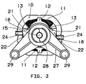
- the motor according to the invention generally comprises a conventional hollow stator 10 of a ferromagnetic material (fig.1) internally provided with a copper wire winding 11 wound upon two insulating elements 12 disposed at opposite locations and defining respective pole pieces 13 (fig. 3).
- the motor further comprises a rotor 14 fixedly secured to a shaft 15 and conventionally formed of a laminated stack of a ferromagnetic material provided with grooves for containing the strands of the rotor winding 16 (fig. 1).
- commutator 17 Fixedly secured to shaft 15 are a commutator 17, a pair of bearings and, when required, one or more pulleys and a rotary speed sensor component. These wholly conventional components have not been depicted in the drawings for the sake of simplicity.
- Rotor 14 has to be mounted and centered within stator 10, to which purpose the state of the art requires the employ of two opposite end plates interconnected by tension bolts, and a number of additional structural elements.
- the machining of the end plates has to be highly accurate, and the assembly of the motor is a complicated, time-consuming and laborious operation.
- the invention instead proposes the employ of only two symmetric half shells 18 formed of an amagnetic material such as plastic, aluminum, a zinc alloy, stainless steel or the like, between which rotor 14 is inclosed for subsequent insertion into the internal space of stator 10.
- An individual half shell 18 is depicted in detail in fig. 2. It has a concave internal surface 19 adapted to conform to the exterior surface of rotor 14, and two opposite profiled end portions 20 adapted to be engaged with complementary end portions of the other half shell so as to enclose the components fixedly secured to rotor shaft 15.
- each half shell 18 is formed with guide means for the insertion of rotor 14 into stator 10 in accurate alignment.
- guide means specifically include two opposite guides 21 adapted to cooperate with the end portions of the pole pieces 13 of stator winding 11, and a guide 22 adapted to cooperate with an internal projection of stator 10 (fig. 3).
- Both guides 21 and guides 22 extend over a limited length with respect to the body of the half shell so that their respective ends act as insertion limiting stops as the rotor is inserted into the stator. In this manner an additional advantage is obtained by the possibility of using half shells of the same dimensions for different dimentions of the rotor/stator (for example, from 35 mm to 55 mm), to always ensure proper centering of the rotor within the stator.
- the half shells 18 are additionally provided with a seat 23 for mounting a brush carrier element 24.
- This seat is simultaneously fashioned as the respective half shell is being formed, and located adjacent the end portion thereof at the side corresponding to the commutator 17 secured to shaft 15.
- each half shall is additionally provided with an internal partition 25 (fig. 2) for preventing the carbon powder produced by the wear of the brushes from entering the voids between the components of the adjacent bearing.
- each half shell 18 is finally provided with an axial extension 26 formed with a seat 30 for the motor mounting brackets and for the optional mounting of rotational speed sensor components.
- the motor mounting brackets 27 are formed as plate members having a tubular sleeve portion 28 for mounting on the respective seat 30, and two arm portions provided with holes 29 for securing them, by means of suitable known fixing elements such as bolts and nuts, to the machine to be equipped with the motor, for instance to the tub of a domestic laundry washer.
Landscapes
- Engineering & Computer Science (AREA)
- Power Engineering (AREA)
- Iron Core Of Rotating Electric Machines (AREA)
- Motor Or Generator Current Collectors (AREA)
- Motor Or Generator Frames (AREA)
- Dc Machiner (AREA)
- Control Of Ac Motors In General (AREA)
- Control Of Washing Machine And Dryer (AREA)
- Main Body Construction Of Washing Machines And Laundry Dryers (AREA)
Claims (4)
- Elektrischer Kommutatormotor, insbesondere für Haushaltswaschmaschinen, enthaltend einen hohlen Stator (10) aus ferromagnetischem Material mit einer zugeordneten Kupferwicklung (11) und einem Rotor (14) aus einem Blechstapel aus ferromagnetischem Material mit Rillen zur Aufnahme der Rotorwicklungsstränge, wobei die Rotorwelle (15) einen fest daran angebrachten Kommutator (17), mehrere Traglager und gegebenenfalls eine Riemenscheibe und ein Rotordrehzahlelement trägt, wobei der Motor dadurch gekennzeichnet ist, daß der Rotor (14) in einem vormontierten Zustand zwischen zwei symmetrischen Halbschalen (18) aus einem amagnetischen Material eingeschlossen ist, die mit profilierten Endabschnitten (20) und axialen Verlängerungen (26) zur Montage der an der Welle (15) befestigten Bauelemente versehen ist, wobei die Halbschalen (18) dazu eingerichtet sind, in den Stator (10) eingeführt zu werden und mit den Endabschnitten der Polstücke (16) desselben in Eingriff zu gelangen.
- Motor nach Anspruch 1, dadurch gekennzeichnet, daß jede Halbschale (18) aus einem einstückigen Element besteht und mit Führungen (21, 22) für den Eingriff mit dem Stator (18) an seiner Außenseite versehen ist und an seiner Innenseite eine querlaufende Staubabscheidewand (28) auf der dem Kommutator (17) zugewandten Seite aufweist.
- Motor nach Anspruch 1, dadurch gekennzeichnet, daß jede Halbschale (18) mit einem Sitz (23) zur Montage eines entsprechenden Bürstentragelements (24) versehen ist.
- Motor nach Anspruch 1, dadurch gekennzeichnet, daß jede Halbschale (18) zwei Sitze (30) an ihren Endabschnitten aufweist, die dazu eingerichtet sind, in einer üblichen elastischen Vibrationsdämpfer-Montagevorrichtung oder in einem steifen Montagebügel (27) montiert zu werden, der mit Einrichtungen (29) zum Montieren des Motors in einer von ihm angetriebenen Maschine versehen ist.
Priority Applications (1)
| Application Number | Priority Date | Filing Date | Title |
|---|---|---|---|
| AT89104390T ATE90484T1 (de) | 1988-03-24 | 1989-03-13 | Elektrischer kommutatormotor, insbesonders fuer haushalts-waschmaschinen. |
Applications Claiming Priority (2)
| Application Number | Priority Date | Filing Date | Title |
|---|---|---|---|
| IT8845711A IT1234591B (it) | 1988-03-24 | 1988-03-24 | Motore elettrico a collettore, in particolare per macchine lavabiancheria domestiche |
| IT4571188 | 1988-03-24 |
Publications (3)
| Publication Number | Publication Date |
|---|---|
| EP0334150A2 EP0334150A2 (de) | 1989-09-27 |
| EP0334150A3 EP0334150A3 (en) | 1990-03-14 |
| EP0334150B1 true EP0334150B1 (de) | 1993-06-09 |
Family
ID=11257515
Family Applications (1)
| Application Number | Title | Priority Date | Filing Date |
|---|---|---|---|
| EP89104390A Expired - Lifetime EP0334150B1 (de) | 1988-03-24 | 1989-03-13 | Elektrischer Kommutatormotor, insbesonders für Haushalts-Waschmaschinen |
Country Status (4)
| Country | Link |
|---|---|
| EP (1) | EP0334150B1 (de) |
| AT (1) | ATE90484T1 (de) |
| DE (1) | DE68906933D1 (de) |
| IT (1) | IT1234591B (de) |
Families Citing this family (1)
| Publication number | Priority date | Publication date | Assignee | Title |
|---|---|---|---|---|
| FR2901430A1 (fr) * | 2006-05-16 | 2007-11-23 | Duna Entpr Sa | Support pour moteurs electriques |
Family Cites Families (4)
| Publication number | Priority date | Publication date | Assignee | Title |
|---|---|---|---|---|
| DE7002020U (de) * | 1970-01-22 | 1970-05-27 | Bosch Elektronik Photokino | Elektrischer kleinmotor. |
| US4076197A (en) * | 1976-06-18 | 1978-02-28 | General Electric Company | Torsional vibration isolating motor mounting arrangement and method of making the same |
| DE2933568A1 (de) * | 1979-08-18 | 1981-03-26 | Robert Bosch Gmbh, 70469 Stuttgart | Wechselstromgenerator |
| US4335323A (en) * | 1980-01-17 | 1982-06-15 | Ambac Industries, Incorporated | Stamped sheet metal frame for dynamoelectric machine |
-
1988
- 1988-03-24 IT IT8845711A patent/IT1234591B/it active
-
1989
- 1989-03-13 EP EP89104390A patent/EP0334150B1/de not_active Expired - Lifetime
- 1989-03-13 AT AT89104390T patent/ATE90484T1/de active
- 1989-03-13 DE DE8989104390T patent/DE68906933D1/de not_active Expired - Lifetime
Also Published As
| Publication number | Publication date |
|---|---|
| IT1234591B (it) | 1992-05-25 |
| EP0334150A2 (de) | 1989-09-27 |
| ATE90484T1 (de) | 1993-06-15 |
| EP0334150A3 (en) | 1990-03-14 |
| DE68906933D1 (de) | 1993-07-15 |
| IT8845711A0 (it) | 1988-03-24 |
Similar Documents
| Publication | Publication Date | Title |
|---|---|---|
| US4546280A (en) | Alternator with unitary brush-holder and bearing hub | |
| JP4188564B2 (ja) | ステータの周りを回転するロータを備えた電気機械 | |
| US6166468A (en) | Rotary electric machine and bearing structure thereof | |
| EP1613835A2 (de) | Flexibles motor-pack für kraftbetriebenes werkzeug und herstellungsverfahren dafür | |
| US4360749A (en) | Automotive alternator construction | |
| US5949174A (en) | Commutator for two speed electric motor and motor incorporating same | |
| CN100355186C (zh) | 端盖组件 | |
| US12562616B2 (en) | Motor with expandable casing | |
| US2683826A (en) | Dynamoelectric machine stator construction | |
| EP0334150B1 (de) | Elektrischer Kommutatormotor, insbesonders für Haushalts-Waschmaschinen | |
| GB2369503A (en) | Direct-drive wheel motor | |
| US3135882A (en) | Fan-cooled dynamoelectric machine | |
| KR20220108062A (ko) | 회전 전기 기계용 브래킷 | |
| JP5948570B2 (ja) | 洗濯機用モータ | |
| US3925696A (en) | Statorless dynamo-electric machine | |
| KR20230112007A (ko) | 고속 모터 및 이의 조립 방법 | |
| SU1690107A1 (ru) | Электрическа машина посто нного тока | |
| US20240421680A1 (en) | Motor with expandable casing | |
| KR102518672B1 (ko) | 멀티 출력을 제공하는 발전기 | |
| KR102718357B1 (ko) | 세탁기용 모터 | |
| CN116134705A (zh) | 电机装置 | |
| JP2003199284A (ja) | モータ | |
| KR200175550Y1 (ko) | 차량용 교류발전기 | |
| US3264505A (en) | Dynamoelectric machine winding connection | |
| JPH0546781B2 (de) |
Legal Events
| Date | Code | Title | Description |
|---|---|---|---|
| PUAI | Public reference made under article 153(3) epc to a published international application that has entered the european phase |
Free format text: ORIGINAL CODE: 0009012 |
|
| AK | Designated contracting states |
Kind code of ref document: A2 Designated state(s): AT DE ES FR GB IT SE |
|
| PUAL | Search report despatched |
Free format text: ORIGINAL CODE: 0009013 |
|
| AK | Designated contracting states |
Kind code of ref document: A3 Designated state(s): AT DE ES FR GB IT SE |
|
| RHK1 | Main classification (correction) |
Ipc: H02K 5/04 |
|
| 17P | Request for examination filed |
Effective date: 19900629 |
|
| 17Q | First examination report despatched |
Effective date: 19920507 |
|
| ITF | It: translation for a ep patent filed | ||
| GRAA | (expected) grant |
Free format text: ORIGINAL CODE: 0009210 |
|
| AK | Designated contracting states |
Kind code of ref document: B1 Designated state(s): AT DE ES FR GB IT SE |
|
| PG25 | Lapsed in a contracting state [announced via postgrant information from national office to epo] |
Ref country code: FR Effective date: 19930609 Ref country code: ES Free format text: THE PATENT HAS BEEN ANNULLED BY A DECISION OF A NATIONAL AUTHORITY Effective date: 19930609 Ref country code: DE Effective date: 19930609 Ref country code: AT Effective date: 19930609 |
|
| REF | Corresponds to: |
Ref document number: 90484 Country of ref document: AT Date of ref document: 19930615 Kind code of ref document: T |
|
| REF | Corresponds to: |
Ref document number: 68906933 Country of ref document: DE Date of ref document: 19930715 |
|
| EN | Fr: translation not filed | ||
| PG25 | Lapsed in a contracting state [announced via postgrant information from national office to epo] |
Ref country code: GB Effective date: 19940313 |
|
| PG25 | Lapsed in a contracting state [announced via postgrant information from national office to epo] |
Ref country code: SE Free format text: LAPSE BECAUSE OF NON-PAYMENT OF DUE FEES Effective date: 19940314 |
|
| PLBE | No opposition filed within time limit |
Free format text: ORIGINAL CODE: 0009261 |
|
| STAA | Information on the status of an ep patent application or granted ep patent |
Free format text: STATUS: NO OPPOSITION FILED WITHIN TIME LIMIT |
|
| 26N | No opposition filed | ||
| GBPC | Gb: european patent ceased through non-payment of renewal fee |
Effective date: 19940313 |
|
| EUG | Se: european patent has lapsed |
Ref document number: 89104390.3 Effective date: 19941010 |
|
| PG25 | Lapsed in a contracting state [announced via postgrant information from national office to epo] |
Ref country code: IT Free format text: LAPSE BECAUSE OF NON-PAYMENT OF DUE FEES;WARNING: LAPSES OF ITALIAN PATENTS WITH EFFECTIVE DATE BEFORE 2007 MAY HAVE OCCURRED AT ANY TIME BEFORE 2007. THE CORRECT EFFECTIVE DATE MAY BE DIFFERENT FROM THE ONE RECORDED. Effective date: 20050313 |