EP0334094A2 - Device for injection of a plastic part onto a paper tube by means of a supporting piece - Google Patents
Device for injection of a plastic part onto a paper tube by means of a supporting piece Download PDFInfo
- Publication number
- EP0334094A2 EP0334094A2 EP19890103955 EP89103955A EP0334094A2 EP 0334094 A2 EP0334094 A2 EP 0334094A2 EP 19890103955 EP19890103955 EP 19890103955 EP 89103955 A EP89103955 A EP 89103955A EP 0334094 A2 EP0334094 A2 EP 0334094A2
- Authority
- EP
- European Patent Office
- Prior art keywords
- edge
- paper tube
- support part
- flat
- injection core
- Prior art date
- Legal status (The legal status is an assumption and is not a legal conclusion. Google has not performed a legal analysis and makes no representation as to the accuracy of the status listed.)
- Granted
Links
- 238000002347 injection Methods 0.000 title claims abstract description 46
- 239000007924 injection Substances 0.000 title claims abstract description 46
- 239000007788 liquid Substances 0.000 claims description 22
- 238000000465 moulding Methods 0.000 claims description 11
- 239000007921 spray Substances 0.000 claims description 10
- 239000011092 plastic-coated paper Substances 0.000 claims description 2
- 238000013461 design Methods 0.000 description 8
- 230000012447 hatching Effects 0.000 description 5
- 239000011324 bead Substances 0.000 description 4
- 238000005452 bending Methods 0.000 description 4
- 238000004519 manufacturing process Methods 0.000 description 4
- 238000003754 machining Methods 0.000 description 3
- 238000000034 method Methods 0.000 description 3
- 238000004806 packaging method and process Methods 0.000 description 3
- 238000007789 sealing Methods 0.000 description 3
- 238000005507 spraying Methods 0.000 description 3
- 238000011835 investigation Methods 0.000 description 2
- 238000012856 packing Methods 0.000 description 2
- 238000004873 anchoring Methods 0.000 description 1
- 230000015572 biosynthetic process Effects 0.000 description 1
- 239000012876 carrier material Substances 0.000 description 1
- 230000006735 deficit Effects 0.000 description 1
- 238000009795 derivation Methods 0.000 description 1
- 238000009826 distribution Methods 0.000 description 1
- 238000005516 engineering process Methods 0.000 description 1
- 239000000835 fiber Substances 0.000 description 1
- 238000001746 injection moulding Methods 0.000 description 1
- 239000000463 material Substances 0.000 description 1
- 238000010137 moulding (plastic) Methods 0.000 description 1
- 229920000642 polymer Polymers 0.000 description 1
- 238000012360 testing method Methods 0.000 description 1
- 230000003313 weakening effect Effects 0.000 description 1
Images


Classifications
-
- B—PERFORMING OPERATIONS; TRANSPORTING
- B29—WORKING OF PLASTICS; WORKING OF SUBSTANCES IN A PLASTIC STATE IN GENERAL
- B29C—SHAPING OR JOINING OF PLASTICS; SHAPING OF MATERIAL IN A PLASTIC STATE, NOT OTHERWISE PROVIDED FOR; AFTER-TREATMENT OF THE SHAPED PRODUCTS, e.g. REPAIRING
- B29C45/00—Injection moulding, i.e. forcing the required volume of moulding material through a nozzle into a closed mould; Apparatus therefor
- B29C45/14—Injection moulding, i.e. forcing the required volume of moulding material through a nozzle into a closed mould; Apparatus therefor incorporating preformed parts or layers, e.g. injection moulding around inserts or for coating articles
- B29C45/14336—Coating a portion of the article, e.g. the edge of the article
-
- B—PERFORMING OPERATIONS; TRANSPORTING
- B29—WORKING OF PLASTICS; WORKING OF SUBSTANCES IN A PLASTIC STATE IN GENERAL
- B29C—SHAPING OR JOINING OF PLASTICS; SHAPING OF MATERIAL IN A PLASTIC STATE, NOT OTHERWISE PROVIDED FOR; AFTER-TREATMENT OF THE SHAPED PRODUCTS, e.g. REPAIRING
- B29C45/00—Injection moulding, i.e. forcing the required volume of moulding material through a nozzle into a closed mould; Apparatus therefor
- B29C45/14—Injection moulding, i.e. forcing the required volume of moulding material through a nozzle into a closed mould; Apparatus therefor incorporating preformed parts or layers, e.g. injection moulding around inserts or for coating articles
- B29C45/14598—Coating tubular articles
Definitions
- the invention relates to a device for molding a plastic part onto a plastic-coated paper tube, in particular a lid onto the paper sleeve of a liquid pack, with a spray core and an outer shape that at least partially encompasses it.
- Such spraying devices are already known and are described below in connection with a packaging machine, in which paper coated with plastic on both sides in web form is pulled off a roll, separated and formed into a paper tube with a round cross section via a longitudinal sealing seam, which also has a cross section round mandrel is pushed on as a spray core and ends with its edge in the spray position in the mold space of the tool (spray core and outer mold) such that the heated, liquid plastic flows into the mold space and completely encompasses the round end edge of the paper tube.
- the paper sleeve in the known machine is closed on one side by the lid, because the lid is made of plastic without a carrier material and, for example, also has the pouring opening at the same time.
- the cover is anchored to the front edge of the paper tube, is supported on it and at the same time seals the open cut surface of this front edge. If you cut a paper web coated on both sides with plastic, then along the cut edge, which after the formation of the sleeve becomes the circular end edge, there is an unprotected edge coated without plastic, which must be protected against the ingress of liquid, because otherwise the liquid enters the paper fibers penetrates between the plastic layers and the packing is destroyed from this cut edge.
- the known injection molding machine therefore has such a molding space that the upper round end edge of the paper tube is not at the edge of the molding space but inside the same ends with the result that the plastic that later completely fills the molding space not only bears on the free end edge, which was the cut surface, but also on both sides next to it, thus sealing the upper edge of the paper tube in a liquid-tight manner.
- the packaging machine for producing liquid packs that are at least partially round in cross section worked satisfactorily in this way.
- the only difference to the round pack for the tool is that the mandrel also becomes quadrangular in cross-section by forming four outer planes, and the correspondingly designed paper sleeve is pushed onto this cuboid mandrel in a comparable position. For the rest, it was believed that there would be no changes in the spraying technique.
- the invention was therefore based on the object to improve the injection device of the type mentioned in such a way that the flat walls of the tube do not bend when the paper tube is square in cross section and the injection point is reliably set everywhere.
- the upper flat edge of the paper tube is one piece after being pushed onto the mandrel protrudes far beyond the upper outer edge of the mandrel, namely in order to protrude into the mold space, is supported from the outside by the wall of the outer mold and now also from the inside according to the invention by the supporting part.
- the support part has the shape of a plate which occupies part of the cross-sectional profile between the injection core and the outer shape, and if the outer end face of the support part is flat and lies parallel to the tube wall in such a way that it lies on the flat edge of the paper tube can be created.
- the end face and also the edge face of a mandrel or injection core is partially shaped by machining, so that straight edges and lines are preferred both in recesses and in elevations on such a workpiece.
- the design of the support part as a plate meets this requirement and therefore facilitates production.
- the support part protruding from the edge surface fills a fraction of the cross-sectional profile of this mold space; by no means the entire cross section of the molding space at the location of the support part. Namely, it must also be ensured in the area of the support part that the free end face of the paper tube, which has lost all edge protection due to the cut, is completely sealed and encapsulated with plastic when the cover is molded on.
- the support part can, however, occupy such a large part of the cross-sectional profile of the molding space that the tensile forces or holding forces between the upper edge of the paper tube and the cover are absent, since the support part is missing, while ensuring the tightness mentioned (edge protection) takes up only a fraction of the entire edge surface, so that the adjacent surfaces are sufficient to compensate for or take over the missing support forces only in the area of the support part.
- the upper edge of the paper tube can be placed directly on the support part and supported, as the name suggests.
- the outer flat end face of the support part opens into the outer plane of the injection-molded core, which is square in cross-section, and lies flush with it, and in the direction of the straight outer edge has a length of 1/90 to 1/20, preferably 1/70 to 1 / 40 the length of the outer edge. If the length of the outer edge is, for example, 70 mm, then a length of the flat end surface of the support part of 1 mm, as seen in the direction of the straight outer edge, is sufficient to ensure effective support of the flat edge of the paper tube.
- the paper tube Due to the flush arrangement of the outer flat end surface of the support part to the outer plane of the injection core and by the opening of the end surface in this outer plane, the paper tube can be pushed onto the injection core or pulled down from it without any impairment, as if no support parts were provided.
- the support is particularly useful if, according to the invention, the outer flat end surface of the support part is rectangular and has a height which is approximately equal to the distance between the straight outer edge of the injection core and the first shoulder of the outer shape.
- the first shoulder of the outer shape mentioned here limits the molding space which will later be filled with plastic to the outside and below the edge of the lid, for example when looking at the lid of the finished, closed liquid pack from above.
- the square end face is covered by the "radial" or “horizontal" outer flange of the lid, which for reasons of strength and tightness extends beyond the free end of the upper edge of the paper tube and is welded to the outside of the plastic layer of the paper tube.
- the invention is advantageously designed in such a way that the edge surface connecting each of the four outer planes of the injection core with its end face is formed from at least two sub-planes that intersect along a central edge, and that the support part has at least the lower sub-plane lying between the central edge and the upper outer edge is attached.
- the upper outer edge of the injection core is referred to here as the "upper" outer edge, because one of about vertically upstanding mandrel or spray core and therefore assumes the end face of the same as "arranged above”.
- the generally flat end face, which forms the inside of the packing lid, is thus connected to the outer plane via the said edge surface.
- the edge surface between the outer plane of the injection core and its end surface could also be formed by curved surfaces and the like, provided that only the molding space around the upper edge of the paper tube is designed in this way, that the above-mentioned features and requirements are met, that is to say the free cut edge, the upper end edge of the tube, is encapsulated in a liquid-tight manner (edge protection) and collar-like injection beads, preferably attached to the inside of the liquid pack, are welded to the edge of the paper tube, so that there is also a mechanical holder of the plastic part (lid of the pack) on the paper tube (the paper sleeve) is guaranteed.
- the edge surface consists of two sub-planes which run in a strip-like manner parallel to the upper outer edge, the lower sub-plane lying between the upper outer edge and a central edge and the upper strip-like sub-plane extending between the central edge and the end surface edge .
- Seen in the profile direction of the support part i.e. Seen in the direction of the upper outer edge, the central edge, the upper outer edge and also the end face edge, which are all three straight, represent points, the partial planes being represented by the connecting lines of these points.
- edge area is planes; if they are curved lines, they are the curved surfaces mentioned above. So planes are preferred, and here it is possible that both sub-planes again lie in one plane, which then form a flat edge surface; in a preferred embodiment, the central edge is somewhat outside, so that two sub-planes set at different angles to one another form the edge surface.
- the shape of the edge surface of the injection core can preferably have the shape of a house roof, the support part according to the invention being attached like a dormer window to at least one of the two part levels.
- the window area of the dormer then corresponds to the outer flat end surface of the support part, because this surface lies parallel and flush with the outer plane of the injection core.
- the rear surface which runs at an angle to this flat end face of the support part and corresponds to the roof area of the dormer, can extend to the end face edge, but can also end in the area of the upper part level or even at the middle edge. While the outer end surface of the support member should be flat to provide the appropriate support for the flat edge of the paper tube, the surface of the support member corresponding to the roof portion of the dormer need not be flat.
- the support part Except for the outer flat end surface of the support part, its design is otherwise uncritical, provided the support part does not take up too much volume in order not to weaken the mechanical tensile and compressive forces mentioned of the plastic which connects the lid to the paper tube of the later liquid pack.
- a useful design of the support parts is plate shape.
- a groove can be made in the edge surface of the injection core and / or beyond the edges thereof by a simple machining movement (planing machine) in such a way that a suitably shaped plate is inserted and welded tight.
- Another manufacturing method could be the support also form part or alternatively weld onto the edge surface without providing a groove in the injection core.
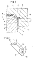
- the mandrel or injection core which is square in cross section, is designated by 4, the external shape by 5 and the support part by 6 net.
- the injection core 4 has four outer planes, of which only the front or right outer plane 7 is shown in FIGS. 1 and 2. On the end face or “above”, the injection core 4 is delimited by the end face 8, which at the end edge 9 merges into the edge face generally designated 10 and which has the straight, upper outer edge 11 in common with the outer plane 7. If the edge surface 10 consists of an upper (12) partial plane and a lower partial plane (13), then they intersect in the central edge 14.
- the support part 6 in the form of the plate is shown in perspective in FIG. 3 and shown in FIG. 1 installed.
- This part 6 mainly depends on the outer flat end surface 17, the surface of which is given by the length 1 (FIG. 1) and height h (FIG. 1).
- the area 17 'shown in Figure 3' is larger than the flat surface 17, because it is extended by the in the body of the injection core behind the outer plane 7 Sene part, so that the total height of the surface 17 'is denoted by H.
- H can be equal to h or greater than h, but certainly not less than h.
- the upper surface 18 of the support part 6, which corresponds to the roof surface of the dormer, is flat in this embodiment and opens at the top in the direction of the end surface 8 in the end edge 9.
- the cross-sectional profile of the support member 6 is created with a simple hatching and designated 6 ', the direction of this single hatching is at a different angle than the hatching of the edge 2 of the paper tube 1. From Figure 2 it can thus be seen that which part in the area of the support part 6 the dormer-like elevation under the plastic cover 16 occupies.
- the support part has a length 1 of 1 to 2 mm, for example 2 mm. Only in this area is the finished plastic lid 16 of the liquid pack lacking the volume 6 'which results from the hatched area 6' in FIG. 2 'multiplied by the length 1.
- the parts of the support part 6 shown in broken lines in FIG. 1 are variable.
- the lower front edge 20 of the support part 6 according to FIG. 3 can be somewhat higher while reducing the height H, and the rear lower edge 21 can also be closer to the rear upper edge 22, which lies in the front edge 9 as shown in FIG. 1 , have come closer.
- the area between the edges 21 and 22 could be completely omitted if, for example, the supporting part 6 is welded to it like a dormer window without being immersed in the edge area 10.
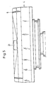
- FIG. 4 The top view of FIG. 4 on the injection core 4 shows the pouring opening 23 in the upper region and a supporting part 6 on the adjacent edge at the top, while three supporting parts 6 are provided along the two lower edges.
- the flow channels 24 for the liquid plastic during the injection process are also indicated in FIG. In the areas of the support part 6 there are small recesses in the plastic bead arranged on the inside of the finished package.
- FIG. 5 shows a side view of the head of the injection core when looking down from FIG. 4, which is why the pouring device 23 can be seen in the middle. At a distance to the right and left of this one can see two support parts 6, which appear in perspective in this representation.
- the head of a spray core 4 ' is shown for another embodiment, in which three recesses 25 are made in the shape of a groove at the top, where support parts are later inserted and fastened.
- the support part can also be integrally formed or welded on. It should be emphasized again that a real preferred alternative is the molding or finishing from a single piece.
- the edge surface 10 or the upper sub-plane 12 and the lower sub-plane 13 can then be machined out by machining so that the support part 6 remains.
- a support part 6 in the form of a plate is assumed, as shown in FIG. 3, which is why in FIG. 1 this plate-shaped support part 6 is drawn as more or less embedded in the injection core 4.
Abstract
Description
Die Erfindung betrifft eine Vorrichtung zum Anspritzen eines Kunststoffteiles an einen mit Kunststoff beschichteten Papiertubus, insbesondere eines Deckels an die Papierhülse einer Flüssigkeitspackung, mit einem Spritzkern und einer diesen wenigstens teilweise umgreifenden Außenform.The invention relates to a device for molding a plastic part onto a plastic-coated paper tube, in particular a lid onto the paper sleeve of a liquid pack, with a spray core and an outer shape that at least partially encompasses it.
Derartige Spritzvorrichtungen sind bereits bekannt und werden im folgenden in Verbindung mit einer Packungsmaschine beschrieben, bei welcher beidseitig mit Kunststoff beschichtetes Papier in Bahnform von einer Rolle abgezogen, vereinzelt und zu einem im Querschnitt runden Papiertubus über eine Längssiegelnaht geformt wird, der auf einen ebenfalls im Querschnitt runden Dorn als Spritzkern aufgeschoben wird und mit seinem Rand in der Spritzposition im Formraum des Werkzeuges (Spritzkern und Außenform) derart endet, daß der erhitzte, flüssige Kunststoff in den Formraum strömt und die runde Stirnkante des Papiertubus vollständig abschließend umgreift. Dadurch wird die Papierhülse in der bekannten Maschine auf einer Seite durch den Deckel verschlossen, denn der Deckel besteht aus Kunststoff ohne Trägermaterial und weist beispielsweise auch zugleich die Ausgießöffnung auf. Der Dekkel ist an der Stirnkante der Papierhülse verankert, stützt sich an dieser ab und dichtet gleichzeitig auch die offene Schnittfläche dieser Stirnkante ab. Schneidet man nämlich eine beidseitig mit Kunststoff beschichtete Papierbahn, dann entsteht längs der Schnittkante, die nach Bildung der Hülse die kreisförmige Stirnkante wird, eine ohne Kunststoff beschichtete, ungeschützte Kante, die gegen Eintritt von Flüssigkeit geschützt werden muß, weil anderenfalls die Flüssigkeit in die Papierfasern zwischen die Kunststoffschichten eindringt und die Packung von dieser Schnittkante aus zerstört. Die bekannte Spritzmaschine weist daher einen solchen Formraum auf, daß die obere runde Stirnkante der Papierhülse nicht am Rand des Formraumes sondern im Inneren desselben mündet mit der Folge, daß der später den Formraum vollständig ausfüllende Kunststoff sich nicht nur auf die freie Stirnkante, welche die Schnittfläche war, sondern auch beidseitig neben diese anlegt und damit den oberen Rand des Papiertubus flüssigkeitsdicht abschließt.Such spraying devices are already known and are described below in connection with a packaging machine, in which paper coated with plastic on both sides in web form is pulled off a roll, separated and formed into a paper tube with a round cross section via a longitudinal sealing seam, which also has a cross section round mandrel is pushed on as a spray core and ends with its edge in the spray position in the mold space of the tool (spray core and outer mold) such that the heated, liquid plastic flows into the mold space and completely encompasses the round end edge of the paper tube. As a result, the paper sleeve in the known machine is closed on one side by the lid, because the lid is made of plastic without a carrier material and, for example, also has the pouring opening at the same time. The cover is anchored to the front edge of the paper tube, is supported on it and at the same time seals the open cut surface of this front edge. If you cut a paper web coated on both sides with plastic, then along the cut edge, which after the formation of the sleeve becomes the circular end edge, there is an unprotected edge coated without plastic, which must be protected against the ingress of liquid, because otherwise the liquid enters the paper fibers penetrates between the plastic layers and the packing is destroyed from this cut edge. The known injection molding machine therefore has such a molding space that the upper round end edge of the paper tube is not at the edge of the molding space but inside the same ends with the result that the plastic that later completely fills the molding space not only bears on the free end edge, which was the cut surface, but also on both sides next to it, thus sealing the upper edge of the paper tube in a liquid-tight manner.
Die Verpackungsmaschine zur Erstellung von im Querschnitt wenigstens teilweise runden Flüssigkeitspackungen arbeitete auf diese Weise zufriedenstellend. Man ist nun aber dazu übergegangen, auch Flüssigkeitspackungen mit viereckigem Querschnitt mit der gleichen Spritztechnik herzustellen. Der Unterschied zu der runden Packung besteht für das Werkzeug nur darin, daß auch der Dorn durch Bildung von vier Außenebenen im Querschnitt viereckig wird und die entsprechend gestaltete Papierhülse in eine vergleichbare Position auf diesen quaderförmigen Dorn aufgeschoben wird. Im übrigen glaubte man, daß sich keinerlei Veränderungen bei der Spritztechnik ergeben.The packaging machine for producing liquid packs that are at least partially round in cross section worked satisfactorily in this way. However, it has now started to also produce liquid packs with a square cross section using the same spraying technique. The only difference to the round pack for the tool is that the mandrel also becomes quadrangular in cross-section by forming four outer planes, and the correspondingly designed paper sleeve is pushed onto this cuboid mandrel in a comparable position. For the rest, it was believed that there would be no changes in the spraying technique.
Nun mußte man aber feststellen, daß die ebene Seitenwandung der viereckigen Flüssigkeitspackung am Ansatz des Deckels undichte Stellen hatte. Zunächst konnte man wegen der sorgfältig hergestellten Werkzeugteile, insbesondere der Endbereiche des Spritzkerns und auch der Außenform, Fehlerquellen für die undichten Stellen nicht entdecken; bis man im Bereich des ebenen Randes des Papiertubus im Abstand von den vier Ecken teilweise Spritzwulste außen und Verdünnungen auf der Innenseite der Flüssigkeitspackung feststellte. Untersuchungen ergaben dann, daß sich die eine oder andere ebene Seitenwandung der Flüssigkeitspackung bzw. der Papierhülse im Bereich des oberen Randes nicht exakt an die ebene Wand der Außenform angelegt hatte.Now, however, it had to be found that the flat side wall of the square liquid pack had leaks at the base of the lid. At first, due to the carefully manufactured tool parts, in particular the end areas of the injection core and also the outer shape, it was not possible to discover sources of error for the leaks; until, in the area of the flat edge of the paper tube, at some distance from the four corners, there were partially beads on the outside and thinning on the inside of the liquid pack. Investigations then showed that one or the other flat side wall of the liquid pack or of the paper sleeve in the region of the upper edge did not lie exactly against the flat wall of the outer shape.
Der Erfindung lag daher die Aufgabe zugrunde, die Anspritzvorrichtung der eingangs bezeichneten Art dahingehend zu verbessern, daß sich bei im Querschnitt viereckigem Papiertubus die ebenen Wandungen des Tubus sich nicht durchbiegen und die Anspritzstelle überall zuverlässig eingestellt ist.The invention was therefore based on the object to improve the injection device of the type mentioned in such a way that the flat walls of the tube do not bend when the paper tube is square in cross section and the injection point is reliably set everywhere.
Während bei der im Querschnitt runden Flüssigkeitspackung mit der runden Papierhülse ausreichende Abstützkräfte durch das Papiermaterial und seine runde Ausgestaltung vorhanden waren, so daß sich der obere Rand der Papierhülse gut an die zylindermantelförmige Wandung der Außenform anlegte und auch der einfließende, erhitzte Kunststoff diesen oberen Rand nicht von der Formwandung wegzudrücken vermochte, hat man bei den erfindungsgemäßen Untersuchungen festgestellt, daß derartige Versteifungs- und Haltekräfte im oberen Rand des Papiertubus durch seine ebene Ausgestaltung zwischen den Ecken verloren gehen. Tatsächlich hat man dann festgestellt, daß sich die ebenen Wandungen im Bereich des oberen Randes beim Spritzvorgang beliebig und zufällig in den Formraum dort hinbewegen bzw. verbiegen, wo sich zunächst freies Volumen befindet, welches durch den einfließenden Kunststoff erst ausgefüllt wird. Betrachtet man beispielsweise die Mitte eines ebenen oberen Randes der Papierhülse, dann kann man sich ein Durchbiegen dieses ebenen Randes von der Wandung der Außenform weg nach innen zum Spritzkern hin vorstellen mit dem Ergebnis, daß zwischen Wandung der Außenform und Außenfläche des oberen ebenen Randes des Papiertubus Kunststoff einfließt und den oben beschriebenen und zu Anfang festgestellten Kunststoffwulst bildet, wo er nicht nur überflüssig sondern sogar deshalb unerwünscht ist, weil die hier überflüssige Menge Kunststoff auf der gegenüberliegenden Innenseite fehlt und daher zu Undichtigkeiten, wenigstens aber Schwächung der Verankerungskräfte führt, durch welche der Deckel später an der Papierhülse gehalten werden soll. Die kleinste Belastung der gefüllten Flüssigkeitspackung führt dann an dieser Schwachstelle zum AufbrechenWhile the liquid pack with the round paper sleeve was round in cross-section, there were sufficient support forces due to the paper material and its round design, so that the upper edge of the paper sleeve fitted well against the cylindrical jacket-shaped wall of the outer shape and the inflowing, heated plastic did not have this upper edge able to push away from the mold wall, it has been found in the investigations according to the invention that such stiffening and holding forces in the upper edge of the paper tube are lost due to its flat design between the corners. In fact, it has then been found that the flat walls in the area of the upper edge move or bend arbitrarily and randomly into the molding space where there is initially free volume, which is only filled in by the inflowing plastic. If you consider, for example, the middle of a flat upper edge of the paper tube, one can imagine a bending of this flat edge inwards from the wall of the outer mold towards the spray core, with the result that between the wall of the outer mold and the outer surface of the upper flat edge of the paper tube Plastic flows in and forms the plastic bead described above and determined at the beginning, where it is not only unnecessary but even undesirable because the excess amount of plastic is missing on the opposite inside and therefore leads to leaks, but at least weakening the anchoring forces, by which the Cover to be held later on the paper sleeve. The slightest load on the filled liquid pack then leads to breakup at this weak point
Um dieses Durchbiegen der Tubuswandung auszuschalten, wird zur Lösung der vorstehend genannten Aufgabe erfindungsgemäß vorgeschlagen, daß an der Randfläche neben der geraden oberen Außenkante des Spritzkerns mindestens ein Abstützteil herausstehend angebracht ist, an welchem der Papierrand in Anlage bringbar ist. Erfindungsgemäß ist der obere ebene Rand des Papiertubus, der nach dem Aufschieben auf den Dorn ein Stück weit über die obere Außenkante des Dorns heraussteht, nämlich um in den Formraum hineinzuragen, von außen durch die Wandung der Außenform abgestützt und nunmehr auch von innen erfindungsgemäß durch das Abstützteil. Trotz der ebenen Form der Seitenwandung der neuen Flüssigkeitspackung bzw. des ebenen Randes des Papiertubus ist mit Vorteil ein Durchbiegen vermieden, so daß die Lage der Stirnfläche des Papiertubus überall zuverlässig eingestellt ist und Schwächungs- oder gar Undichtigkeitsstellen der fertigen Flüssigkeitsverpackung eliminiert sind.In order to eliminate this bending of the tube wall, it is proposed according to the invention to achieve the above-mentioned object that at least one support part is protrudingly attached to the edge surface next to the straight upper outer edge of the injection core, on which the paper edge can be brought into contact. According to the invention, the upper flat edge of the paper tube is one piece after being pushed onto the mandrel protrudes far beyond the upper outer edge of the mandrel, namely in order to protrude into the mold space, is supported from the outside by the wall of the outer mold and now also from the inside according to the invention by the supporting part. Despite the flat shape of the side wall of the new liquid pack or the flat edge of the paper tube, bending is advantageously avoided, so that the position of the end face of the paper tube is set reliably everywhere and weak points or even leaks in the finished liquid packaging are eliminated.
Zweckmäßig ist es erfindungsgemäß dabei, wenn das Abstützteil die Gestalt eines Plättchens hat, welches einen Teil des Querschnittsprofils zwischen Spritzkern und Außenform einnimmt, und wenn die äußere Endfläche des Abstützteils eben ist und parallel zur Tubuswandung derart liegt, daß sie an den ebenen Rand des Papiertubus anlegbar ist. Die Stirnfläche und auch die Randfläche eines Dornes bzw. Spritzkernes wird teilweise durch spanabhebende Bearbeitung geformt, so daß gerade Kanten und Linien sowohl bei Ausnehmungen wie auch bei Erhebungen an einem solchen Werkstück bevorzugt sind. Die Ausgestaltung des Abstützteils als Plättchen kommt diesem Erfordernis nach und erleichtert daher die Herstellung. Betrachtet man den Formraum zwischen Spritzkern und Außenform, der einerseits den ebenen Rand des Papiertubus und andererseits den eingespritzten Kunststoff aufnimmt, dann füllt das aus der Randfläche vorstehende Abstützteil einen Bruchteil des Querschnittsprofiles dieses Formraumes aus; keinesfalls den gesamten Querschnitt des Formraumes an der Stelle des Abstützteils. Es muß nämlich auch im Bereich des Abstützteiles dafür gesorgt sein, daß die freie Stirnfläche des Papiertubus, welche durch den Schnitt jeden Kantenschutz verloren hat, vollständig beim Anspritzen des Deckels mit Kunststoff abgedichtet und umspritzt ist. Das Abstützteil kann aber einen derart großen Teil des Querschnittsprofils des Formraumes einnehmen, daß bei Gewährleistung der genannten Dichtigkeit (Kantenschutz) die Zugkräfte oder Halterungskräfte zwischen oberem Rand des Papiertubus und Deckel fehlen, denn das Abstützteil nimmt nur einen Bruchteil der gesamten Randfläche ein, so daß die benachbarten Flächen ausreichen, um diese nur im Bereich des Abstützteils fehlenden Halterungskräfte auszugleichen bzw. zu übernehmen.It is expedient according to the invention if the support part has the shape of a plate which occupies part of the cross-sectional profile between the injection core and the outer shape, and if the outer end face of the support part is flat and lies parallel to the tube wall in such a way that it lies on the flat edge of the paper tube can be created. The end face and also the edge face of a mandrel or injection core is partially shaped by machining, so that straight edges and lines are preferred both in recesses and in elevations on such a workpiece. The design of the support part as a plate meets this requirement and therefore facilitates production. If one looks at the mold space between the injection core and the outer mold, which on the one hand receives the flat edge of the paper tube and on the other hand the injected plastic, then the support part protruding from the edge surface fills a fraction of the cross-sectional profile of this mold space; by no means the entire cross section of the molding space at the location of the support part. Namely, it must also be ensured in the area of the support part that the free end face of the paper tube, which has lost all edge protection due to the cut, is completely sealed and encapsulated with plastic when the cover is molded on. The support part can, however, occupy such a large part of the cross-sectional profile of the molding space that the tensile forces or holding forces between the upper edge of the paper tube and the cover are absent, since the support part is missing, while ensuring the tightness mentioned (edge protection) takes up only a fraction of the entire edge surface, so that the adjacent surfaces are sufficient to compensate for or take over the missing support forces only in the area of the support part.
Durch die parallele Anordnung der äußeren Endfläche des Abstützteils zur Tubuswandung bzw. zur Außenebene des Spritzkerns und durch die ebene Ausgestaltung der Endfläche des Abstützteils kann sich der obere Rand des Papiertubus direkt an das Abstützteil anlegen und abgestützt werden, wie der Name sagt.Due to the parallel arrangement of the outer end surface of the support part to the tube wall or to the outer plane of the injection core and by the flat design of the end surface of the support part, the upper edge of the paper tube can be placed directly on the support part and supported, as the name suggests.
Günstig ist es ferner, wenn erfindungsgemäß die äußere ebene Endfläche des Abstützteils in die Außenebene des im Querschnitt viereckigen Spritzkerns mündet und bündig zu dieser liegt und in Richtung der geraden Außenkante eine Länge von 1/90 bis 1/20, vorzugsweise 1/70 bis 1/40 der Länge der Außenkante hat. Beträgt die Länge der Außenkante beispielsweise 70 mm, dann genügt bereits eine Länge der ebenen Endfläche des Abstützteils von 1 mm, in Richtung der geraden Außenkante gesehen, um eine wirkungsvolle Abstützung des ebenen Randes des Papiertubus zu gewährleisten. Durch die bündige Anordnung der äußeren ebenen Endfläche des Abstützteils zur Außenebene des Spritzkerns und durch das Einmünden der Endfläche in diese Außenebene kann man den Papiertubus ohne jede Beeinträchtigung auf den Spritzkern schieben oder von diesem herunterziehen, als wenn keine Abstützteile vorgesehen wären.It is also advantageous if, according to the invention, the outer flat end face of the support part opens into the outer plane of the injection-molded core, which is square in cross-section, and lies flush with it, and in the direction of the straight outer edge has a length of 1/90 to 1/20, preferably 1/70 to 1 / 40 the length of the outer edge. If the length of the outer edge is, for example, 70 mm, then a length of the flat end surface of the support part of 1 mm, as seen in the direction of the straight outer edge, is sufficient to ensure effective support of the flat edge of the paper tube. Due to the flush arrangement of the outer flat end surface of the support part to the outer plane of the injection core and by the opening of the end surface in this outer plane, the paper tube can be pushed onto the injection core or pulled down from it without any impairment, as if no support parts were provided.
Es ist vorteilhaft, wenn mehrere Abstützteile in gleicher Höhe an der Randfläche des Spritzkerns befestigt sind, beispielsweise bei einem Spritzkern mit einer Länge der geraden Außenkante von 70 mm drei Abstützteile, deren jeweils äußere ebene Endfläche - in Richtung der geraden Außenkante gesehen - eine Länge von 1 mm hat. Insgesamt ergibt sich damit eine Abstützlänge von 3 mm, welche durch die vorzugsweise gleichmäßige Verteilung über die gerade Außenkante des Spritzkerns ein Durchbiegen des ebenen Randes des Papiertubus mit Sicherheit ausschaltet.It is advantageous if several support parts are attached to the edge surface of the injection core at the same height, for example, in the case of an injection core with a length of the straight outer edge of 70 mm, three support parts, the outer flat end surface of which - as viewed in the direction of the straight outer edge - has a length of 1 mm. Overall, this results in a support length of 3 mm, which, due to the preferably even distribution over the straight outer edge of the injection core, reliably prevents bending of the flat edge of the paper tube.
Versuche haben ergeben, daß die Abstützung besonders zweckmäßig dann gelingt, wenn erfindungsgemäß die äußere ebene Endfläche des Abstützteils rechteckig ist und eine Höhe hat, die etwa gleich dem Abstand der geraden Außenkante des Spritzkerns von der ersten Schulter der Außenform ist. Die hier angesprochene erste Schulter der Außenform begrenzt den später mit Kunststoff gefüllten Formraum nach außerhalb und unterhalb des Deckelrandes, wenn man beispielsweise von oben auf den Deckel der fertigen, geschlossenen Flüssigkeitspackung blickt. Die viereckige Stirnfläche ist durch den "radialen" oder auch "horizontalen" Außenflansch des Deckels bedeckt, welcher außen aus Festigkeits- und Dichtigkeitsgründen ein Stück weit über das freie Ende des oberen Randes des Papiertubus hinweggreift und außen auf der Kunststoffschicht des Papiertubus angeschweißt ist.Tests have shown that the support is particularly useful if, according to the invention, the outer flat end surface of the support part is rectangular and has a height which is approximately equal to the distance between the straight outer edge of the injection core and the first shoulder of the outer shape. The first shoulder of the outer shape mentioned here limits the molding space which will later be filled with plastic to the outside and below the edge of the lid, for example when looking at the lid of the finished, closed liquid pack from above. The square end face is covered by the "radial" or "horizontal" outer flange of the lid, which for reasons of strength and tightness extends beyond the free end of the upper edge of the paper tube and is welded to the outside of the plastic layer of the paper tube.
Wenn nun, wie vorstehend erwähnt, die äußere ebene Endfläche des Abstützteils die besagte Höhe hat, welche etwa auf der Höhe dieser ersten Schulter der Außenform endet, dann ist die vollständige Flüssigkeitsabdichtung der Stirnkante des Papiertubus gewährleistet, wie oben erwähnt, wenngleich die bei Druckbelastungen der gefüllten fertigen Flüssigkeitspackung auftretenden Zugkräfte an dieser Stelle, wo zuvor das Abstützteil gesessen hatte, nicht ausreichen. Die benachbarten Bereiche nehmen aber die notwendigen Zugkräfte auf, wie sich gezeigt hat. Trotz der definierten kleinen Ausnehmungen des Kunststofformlings sitzt dieser (der ja den Deckel der Pakkung bildet) ausreichend fest verankert am Rand des Papiertubus.If, as mentioned above, if the outer flat end face of the support part has the said height, which ends approximately at the height of this first shoulder of the outer shape, then the complete liquid sealing of the end edge of the paper tube is ensured, as mentioned above, even if the pressure loads on the filled tensile forces occurring at this point where the support part had previously sat are not sufficient. The neighboring areas absorb the necessary tensile forces, as has been shown. Despite the defined small recesses in the plastic molding, the plastic (which forms the lid of the package) is sufficiently firmly anchored on the edge of the paper tube.
Weiterhin ist die Erfindung dadurch vorteilhaft ausgestaltet, daß die jede der vier Außenebenen des Spritzkerns mit seiner Stirnfläche verbindende Randfläche aus wenigstens zwei Teilebenen gebildet ist, die sich längs einer Mittelkante schneiden, und daß das Abstützteil wenigstens aber unteren, zwischen Mittelkante und oberer Außenkante liegenden Teilebene befestigt ist. Die obere Außenkante des Spritzkerns wird hier als "obere" Außenkante bezeichnet, weil man von einem etwa vertikal hochstehenden Dorn bzw. Spritzkern ausgeht und daher die Stirnfläche desselben als "oben" angeordnet annimmt. Die im allgemeinen ebene Stirnfläche, welche die Innenseite des Packungsdeckels bildet, wird also über die genannte Randfläche mit der Außenebene verbunden. Dabei versteht es sich, daß bei einer im Querschnitt viereckigen Packung vier Außenebenen, vorzugsweise unter rechten Winkel zueinander, angestellt sind und so den Papiertubus bilden. Jede Außenebene des Papiertubus und damit auch des Spritzkerns endet zur Stirnfläche hin also in der genannten "geraden, oberen Außenkante". Es ist zwar möglich, die Randfläche zwischen der Außenebene des Spritzkerns und seiner Stirnfläche aus einer oder mehreren Ebenen zu gestalten, die Randfläche könnte aber auch durch gewölbte Flächen und dergleichen gebildet sein, sofern nur der Formraum um den oberen Rand des Papiertubus derart ausgestaltet ist, daß die vorstehend genannten Merkmale und Erfordernisse erfüllt sind, daß also die freie Schnittkante, die obere Stirnkante des Tubus, flüssigkeitsdicht (Kantenschutz) umspritzt ist und bundartige Spritzwulste, vorzugsweise auf der Flüssigkeitspackungsinnenseite angebracht, am Rand des Papiertubus angeschweißt sind, damit auch eine mechanische Halterung des Kunststoffteiles (Deckels der Packung) am Papiertubus (der Papierhülse) gewährleistet ist.Furthermore, the invention is advantageously designed in such a way that the edge surface connecting each of the four outer planes of the injection core with its end face is formed from at least two sub-planes that intersect along a central edge, and that the support part has at least the lower sub-plane lying between the central edge and the upper outer edge is attached. The upper outer edge of the injection core is referred to here as the "upper" outer edge, because one of about vertically upstanding mandrel or spray core and therefore assumes the end face of the same as "arranged above". The generally flat end face, which forms the inside of the packing lid, is thus connected to the outer plane via the said edge surface. It goes without saying that four outer planes, preferably at right angles to one another, are set in a package with a square cross section and thus form the paper tube. Each outer plane of the paper tube and thus also the spray core ends towards the end face in the "straight, upper outer edge" mentioned. Although it is possible to design the edge surface between the outer plane of the injection core and its end surface from one or more planes, the edge surface could also be formed by curved surfaces and the like, provided that only the molding space around the upper edge of the paper tube is designed in this way, that the above-mentioned features and requirements are met, that is to say the free cut edge, the upper end edge of the tube, is encapsulated in a liquid-tight manner (edge protection) and collar-like injection beads, preferably attached to the inside of the liquid pack, are welded to the edge of the paper tube, so that there is also a mechanical holder of the plastic part (lid of the pack) on the paper tube (the paper sleeve) is guaranteed.
Erfindungsgemäß ist es bevorzugt und herstellungstechnisch zweckmäßig, wenn die Randfläche aus zwei Teilebenen besteht, die streifenförmig parallel zur oberen Außenkante verlaufen, wobei die untere Teilebene zwischen der oberen Außenkante und einer Mittelkante liegt und sich die obere streifenartige Teilebene sich zwischen der Mittelkante und der Stirnflächenkante erstreckt. In Profilrichtung des Abstützteiles gesehen, d.h. in Richtung der oberen Außenkante gesehen, stellen sich die Mittelkante, die obere Außenkante und auch die Stirnflächenkante, die ja alle drei gerade sind, Punkte dar, wobei die Teilebenen durch die Verbindungslinien dieser Punkte dargestellt werden.According to the invention, it is preferred and expedient from the point of view of production technology if the edge surface consists of two sub-planes which run in a strip-like manner parallel to the upper outer edge, the lower sub-plane lying between the upper outer edge and a central edge and the upper strip-like sub-plane extending between the central edge and the end surface edge . Seen in the profile direction of the support part, i.e. Seen in the direction of the upper outer edge, the central edge, the upper outer edge and also the end face edge, which are all three straight, represent points, the partial planes being represented by the connecting lines of these points.
Sind diese Verbindungslinien zwischen den die Kanten darstel lenden Punkten Geraden, dann sind die Teilflächen der gesamten sogenannten "Randfläche" Ebenen; sind es gekrümmte Linien, dann handelt es sich um die vorstehend erwähnten gekrümmten Flächen. Bevorzugt sind also Ebenen, und hierbei ist es möglich, daß beide Teilebenen wiederum in einer Ebene liegen, welche dann eine ebene Randfläche bilden; bei einer bevorzugten Ausführungsform liegt die Mittelkante aber etwas außerhalb, so daß zwei unter verschiedenem Winkel zueinander angestellte Teilebenen die Randfläche bilden. Die Form der Randfläche des Spritzkerns kann vorzugsweise die Form eines Hausdaches haben, wobei das Abstützteil gemäß der Erfindung wie eine Dachgaube an mindestens einer der zwei Teilebenen angebracht ist. Der Fensterbereich der Gaube entspricht dann der äußeren ebenen Endfläche des Abstützteils, denn diese Fläche liegt parallel und bündig zur Außenebene des Spritzkerns. Die hintere, unter einem Winkel zu dieser ebenen Endfläche des Abstützteils verlaufende und dem Dachbereich der Gaube entsprechende Fläche kann bis zur Stirnflächenkante reichen, kann aber auch im Bereich der oberen Teilebene oder sogar bereits an der Mittelkante enden. Während die äußere Endfläche des Abstützteils eben sein sollte, um dem ebenen Rand des Papiertubus die geeignete Abstützung zu geben, braucht die dem Dachteil der Gaube entsprechende Fläche des Abstützteils nicht eben zu sein. Bis auf die äußere ebene Endfläche des Abstützteils ist dessen Gestaltung im übrigen unkritisch, sofern das Abstützteil ein nicht zu großes Volumen einnimmt, um die erwähnten mechanischen Zug- und Druckkräfte des Kunststoffes nicht zu schwächen, welcher den Deckel mit dem Papiertubus der späteren Flüssigkeitspackung verbindet.Are these connecting lines between the edges if the points are straight lines, then the partial areas of the entire so-called "edge area" are planes; if they are curved lines, they are the curved surfaces mentioned above. So planes are preferred, and here it is possible that both sub-planes again lie in one plane, which then form a flat edge surface; in a preferred embodiment, the central edge is somewhat outside, so that two sub-planes set at different angles to one another form the edge surface. The shape of the edge surface of the injection core can preferably have the shape of a house roof, the support part according to the invention being attached like a dormer window to at least one of the two part levels. The window area of the dormer then corresponds to the outer flat end surface of the support part, because this surface lies parallel and flush with the outer plane of the injection core. The rear surface, which runs at an angle to this flat end face of the support part and corresponds to the roof area of the dormer, can extend to the end face edge, but can also end in the area of the upper part level or even at the middle edge. While the outer end surface of the support member should be flat to provide the appropriate support for the flat edge of the paper tube, the surface of the support member corresponding to the roof portion of the dormer need not be flat. Except for the outer flat end surface of the support part, its design is otherwise uncritical, provided the support part does not take up too much volume in order not to weaken the mechanical tensile and compressive forces mentioned of the plastic which connects the lid to the paper tube of the later liquid pack.
Eine zweckmäßige Ausgestaltung der Abstützteile ist Plättchenform. Beispielsweise kann man in die Randfläche des Spritzkerns und/oder über deren Ränder hinaus durch eine einfache spanende Bewegung (Hobelmaschine) eine Nut derart einbringen, daß ein geeignet geformtes Plättchen eingelegt und festgeschweißt wird. Damit ist das Abstützteil preiswert, exakt und zuverlässig herstellbar und am Spritzkern befestigt. Bei einer anderen Herstellungsmethode könnte man das Abstütz teil auch anformen oder alternativ ohne Vorsehen einer Nut im Spritzkern auf die Randfläche aufschweißen.A useful design of the support parts is plate shape. For example, a groove can be made in the edge surface of the injection core and / or beyond the edges thereof by a simple machining movement (planing machine) in such a way that a suitably shaped plate is inserted and welded tight. This makes the support part inexpensive, precise and reliable to manufacture and fastened to the injection core. Another manufacturing method could be the support also form part or alternatively weld onto the edge surface without providing a groove in the injection core.
Weitere Vorteile, Merkmale und Anwendungsmöglichkeiten der vorliegenden Erfindung ergeben sich aus der folgenden Beschreibung bevorzugter Ausführungsformen in Verbindung mit den Zeichnungen. Es zeigen:
- Figur 1 schematisch, perspektivisch und abgebrochen das obere Ende eines Spritzkerns mit einem abgebrochenen Teil des Papiertubusrandes,
Figur 2 eine vertikale Schnittansicht, schematisch und abgebrochen bei geschlossenem Formraum und eingespritztem Deckel im Bereich des Abstützteils,Figur 3 perspektivisch ein das Abstützteil bildendes Plättchen einer speziellen Ausführungsart,Figur 4 die Draufsicht auf den Spritzkern, wobei einige Fließkanäle für den Kunststoff und außen einige Abstützteile angedeutet sind,Figur 5 die Seitenansicht des Spritzkerns, wenn manFigur 4 von oben nach unten betrachtet, d.h. von der Spitze der Ausgießöffnung her gesehen, undFigur 6 eine andere Seitenansicht des oberen Spritzkerns mit eingebrachten Nuten für die plättchenförmigen Abstützteile.
- FIG. 1 shows schematically, in perspective and broken off the upper end of a spray core with a broken off part of the edge of the paper tube,
- FIG. 2 shows a vertical sectional view, schematically and broken off with the mold space closed and the cover injected in the region of the support part,
- FIG. 3 is a perspective view of a plate of a special embodiment that forms the support part,
- FIG. 4 shows the top view of the injection core, some flow channels for the plastic and some supporting parts being indicated on the outside,
- FIG. 5 shows the side view of the injection core when looking at FIG. 4 from top to bottom, ie seen from the tip of the pouring opening, and
- Figure 6 is another side view of the upper injection core with grooves for the platelet-shaped support parts.
Der Leser kann sich ohne weiteres einen im Querschnitt viereckigen, vorzugsweise quadratischen, Papiertubus vorstellen, dessen rechtes hinteres Ende in Figur 1 perspektivisch und abgebrochen und in Figur 2 in der Schnittansicht bei 1 gezeigt ist, wobei der ebene Rand des Papiertubus in den Figuren 1 und 2 mit 2 bezeichnet ist und das obere Ende des Papiertubus 1 darstellt. In beiden Figuren erkennt man daher auch deutlich die freie obere Stirnkante 3 (ohne Kantenschutz in Figur 1).The reader can easily imagine a paper tube with a square, preferably square, cross section, the right rear end of which is shown in perspective and broken in FIG. 1 and shown in the sectional view at 1 in FIG. 2, the flat edge of the paper tube in FIGS 2 is designated 2 and represents the upper end of the paper tube 1. The free upper end edge 3 (without edge protection in FIG. 1) can therefore clearly be seen in both figures.
Mit 4 ist der im Querschnitt quadratische Dorn bzw. Spritzkern, mit 5 die Außenform und mit 6 das Abstützteil bezeich net.The mandrel or injection core, which is square in cross section, is designated by 4, the external shape by 5 and the support part by 6 net.
Der Spritzkern 4 hat vier Außenebenen, von denen in den Figuren 1 und 2 nur die vordere bzw. rechte Außenebene 7 gezeigt ist. Stirnseitig bzw. "oben" ist der Spritzkern 4 durch die Stirnfläche 8 begrenzt, die an der Stirnkante 9 in die allgemein mit 10 bezeichnete Randfläche übergeht und mit der Außenebene 7 die gerade, obere Außenkante 11 gemeinsam hat. Besteht die Randfläche 10 aus einer oberen (12) Teilebene und einer unteren Teilebene (13), dann schneiden die sich in der Mittelkante 14.The
Entsprechende Flächen, Kanten und Ausnehmungen trägt auch die Außenform 5, von der für das Verständnis der Erfindung hier nur in Figur 2 die erste Schulter 15 gezeigt ist, auf deren Höhe eine gestrichelte Linie nach rechts gezogen ist, von der im Abstand A die zweite gestrichelte Linie darunter durch die obere Außenkante 11 gelegt ist. Man erkennt aus Figur 2 auch, daß die durch das Niveau der ersten Schulter 15 gelegte gestrichelte Linie (Figur 2) etwa in Höhe der Mittelkante 14 liegt.Corresponding surfaces, edges and recesses are also carried by the
Die vorstehende Beschreibung gibt in etwa die Gestalt des Formraumes zwischen Spritzkern 4 und Außenform 5 an, wobei das beispielsweise den Deckel einer Flüssigkeitspackung bildende Kunststoffteil 16 mit Kreuzschraffur versehen ist, während der ebene Rand des Papiertubus 2 wie auch die Seitenwand des Papiertubus 1 in Figur 2 lediglich eine Einfachschraffur trägt.The above description gives approximately the shape of the mold space between the
Das Abstützteil 6 in Form des Plättchens ist bei einer speziellen Ausführungsform perspektivisch herausgenommen in Figur 3 und eingebaut in Figur 1 gezeigt. Bei diesem Teil 6 kommt es hauptsächlich auf die äußere ebene Endfläche 17 an, deren Fläche durch die Länge 1 (Figur 1) und Höhe h (Figur 1) gegeben ist. Die in Figur 3 gezeigte Fläche 17′ ist größer als die ebene Fläche 17, denn sie verlängert sich um das in den Körper des Spritzkerns hinter der Außenebene 7 eingelas sene Teil, so daß die Gesamthöhe der Fläche 17′ mit H bezeichnet ist. Bei entsprechender Ausgestaltung des Abstützteils 6 kann H gleich h oder größer als h sein, sicher jedoch nicht kleiner als h.In a special embodiment, the
Aus Figur 1 sieht man diejenigen Teile des Abstützteils 6, welche aus der Randfläche 10 dachgaubenartig hervorstehen, mit ausgezogenen Linien gezeichnet, während die im Spritzkern 4 eingetauchten Restteile mit gestrichelten Linien angedeutet sind. Die obere Fläche 18 des Abstützteils 6, welche der Dachfläche der Gaube entspricht, ist bei dieser Ausführungsform eben und mündet oben in Richtung der Stirnfläche 8 in der Stirnkante 9.1 shows those parts of the
In der Querschnittsdarstellung der Figur 2 ist das Querschnittsprofil des Abstützteils 6 mit einer einfachen Schraffur angelegt und mit 6′ bezeichnet, wobei die Richtung dieser Einfachschraffur unter einem anderen Winkel steht als die Schraffur des Randes 2 des Papiertubus 1. Aus Figur 2 erkennt man also, welchen Teil im Bereich des Abstützteils 6 die dachgaubenartige Erhebung unter dem Kunststoffdeckel 16 einnimmt. Das Abstützteil hat eine Länge 1 von 1 bis 2 mm, z.B. 2 mm. Nur in diesem Bereich fehlt dem fertigen Kunststoffdekkel 16 der Flüssigkeitspackung das Volumen 6′ welches sich aus der in Figur 2 schraffierten Fläche 6′ multipliziert mit der Länge 1 ergibt. Im Bereich des Abstützteils 6 ergibt sich also ein Querschnittsprofil mit dem Kunststoffteil (Deckel der Flüssigkeitspackung) 16 einerseits und dem oberen Rand 2 des Papiertubus 1 andererseits, wie mit ausgezogenen Linien in Figur 2 zu sehen ist. Im übrigen fehlt dieses Volumen 6′ an Kunststoff nicht sondern trägt zur Ableitung der mechanischen Druck-, Zug- und Haltekräfte bei, so daß der in Figur 2 mit Kreuzschraffur gezeigte Bereich um die Fläche 6′ vergrößert werden müßte. Man erkennt deutlich, wie die Haltekräfte über die gestrichelte Linie in Figur 2 bis zum Punkt 11 geführt werden, der obere Rand 2 des Papiertubus 1 also fest am Kunststoffteil 16 verankert ist.In the cross-sectional view of Figure 2, the cross-sectional profile of the
Während die Größe und Lage der ebenen Fläche 17 des Abstützteils 6, d.h. die Größen 1 (Länge in Richtung der Außenkante 11 gemessen), Höhe h oberhalb der Außenkaten 11 wichtig sind, sind die gestrichelt dargestellten Teile des Abstützteils 6 in Figur 1 veränderlich. So kann beispielsweise die untere vordere Kante 20 des Abstützteils 6 gemäß Figur 3 unter Verkleinerung der Höhe H etwas höher liegen, und auch die hintere untere Kante 21 kann näher an der hinteren oberen Kante 22, welche in der Stirnkante 9 gemäß Darstellung der Figur 1 liegt, herangerückt sein. Gegebenenfalls könnte die Fläche zwischen den Kanten 21 und 22 vollständig entfallen, wenn beispielsweise das Abstützteil 6 wie eine Dachgaube, ohne in die Randfläche 10 einzutauchen, an dieser angeschweißt wird.While the size and location of the
Die Draufsicht der Figur 4 auf den Spritzkern 4 zeigt im oberen Bereich die Ausgießöffnung 23 und am benachbarten Rand oben jeweils ein Abstützteil 6, während längs der beiden unteren Kanten jeweils drei Abstützteile 6 vorgesehen sind. In Figur 4 sind auch die Fließkanäle 24 für den flüssigen Kunststoff beim Spritzvorgang angedeutet. In den Bereichen des Abstützteils 6 ergeben sich kleine Ausnehmungen in dem auf der Innenseite der späteren fertigen Packung angeordneten Kunststoffwulst.The top view of FIG. 4 on the
In Figur 5 ist eine Seitenansicht des Kopfes des Spritzkerns gezeigt, wenn man in Figur 4 von oben nach unten blickt, weshalb in der Mitte die Ausgießvorrichtung 23 erkennbar ist. Im Abstand rechts und links von dieser erkennt man zwei Abstützteile 6, die bei dieser Darstellung perspektivisch erscheinen.FIG. 5 shows a side view of the head of the injection core when looking down from FIG. 4, which is why the pouring
In Figur 6 schließlich ist für eine andere Ausführungsform der Kopf eines Spritzkerns 4′ gezeigt, bei welchem oben an der Kante drei Ausnehmungen 25 in Nutenform eingebracht sind, wo später Abstützteile eingelegt und befestigt werden.Finally, in Figure 6, the head of a spray core 4 'is shown for another embodiment, in which three recesses 25 are made in the shape of a groove at the top, where support parts are later inserted and fastened.
Auf Seite 11 der Beschreibung oben ist bereits erwähnt, daß das Abstützteil auch angeformt oder aufgeschweißt sein kann. Es sei hier nochmals betont, daß eine echte bevorzugte Alternative das Anformen bzw. Ausarbeiten aus einem Stück ist. Durch spanabhebende Bearbeitung können dann die Randfläche 10 bzw. die obere Teilebene 12 und die untere Teilebene 13 so herausgearbeitet werden, daß das Abstützteil 6 stehenbleibt.On
Bei der einen vorstehend beschriebenen bevorzugten Ausführungsform geht man von einem Abstützteil 6 in Form eines Plättchens aus, wie in Figur 3 gezeigt ist, weshalb in Figur 1 dieses plattenförmige Abstützteil 6 als mehr oder weniger in den Spritzkern 4 eingelassen gezeichnet ist.In the one preferred embodiment described above, a
Bei der ebenfalls vorteilhaften Ausführungsform, bei welcher an ein Ausarbeiten von einem Stück gedacht ist, versteht es sich, daß es keine Plättchenform gibt, wie in Figur 3 dargestellt ist, und daß dann sowohl die gestrichelte als auch die strichpunktierte Linie in Figur 1 neben dem Abstützteil 6 entfallen, wobei dann die die Außenkante 11 darstellende Linie durchgezogen gezeichnet sein muß.In the likewise advantageous embodiment, in which a piece is worked out, it goes without saying that there is no platelet shape, as shown in FIG. 3, and that both the dashed and the dash-dotted line in FIG. 1 next to the
Claims (5)
Priority Applications (1)
| Application Number | Priority Date | Filing Date | Title |
|---|---|---|---|
| AT89103955T ATE95109T1 (en) | 1988-03-19 | 1989-03-07 | DEVICE FOR INJECTING A PLASTIC PART TO A PAPER TUBE USING A SUPPORT PART. |
Applications Claiming Priority (2)
| Application Number | Priority Date | Filing Date | Title |
|---|---|---|---|
| DE3809275A DE3809275A1 (en) | 1988-03-19 | 1988-03-19 | DEVICE FOR INJECTIONING A PLASTIC PART ON A PAPER TUBE USING A SUPPORT PART |
| DE3809275 | 1988-03-19 |
Publications (3)
| Publication Number | Publication Date |
|---|---|
| EP0334094A2 true EP0334094A2 (en) | 1989-09-27 |
| EP0334094A3 EP0334094A3 (en) | 1991-01-30 |
| EP0334094B1 EP0334094B1 (en) | 1993-09-29 |
Family
ID=6350174
Family Applications (1)
| Application Number | Title | Priority Date | Filing Date |
|---|---|---|---|
| EP89103955A Expired - Lifetime EP0334094B1 (en) | 1988-03-19 | 1989-03-07 | Device for injection of a plastic part onto a paper tube by means of a supporting piece |
Country Status (10)
| Country | Link |
|---|---|
| US (1) | US4952130A (en) |
| EP (1) | EP0334094B1 (en) |
| JP (1) | JPH01275112A (en) |
| CN (1) | CN1018989B (en) |
| AT (1) | ATE95109T1 (en) |
| AU (1) | AU615993B2 (en) |
| BR (1) | BR8901241A (en) |
| CA (1) | CA1328967C (en) |
| DE (2) | DE3809275A1 (en) |
| ES (1) | ES2043916T3 (en) |
Cited By (2)
| Publication number | Priority date | Publication date | Assignee | Title |
|---|---|---|---|---|
| EP0443369A2 (en) * | 1990-02-20 | 1991-08-28 | Tetra Laval Holdings & Finance SA | Package for flowable products with reccesses for handling and process for its production |
| EP2234785A1 (en) * | 2007-12-18 | 2010-10-06 | Tetra Laval Holdings & Finance SA | An apparatus and a method for moulding a part of a packaging container |
Families Citing this family (5)
| Publication number | Priority date | Publication date | Assignee | Title |
|---|---|---|---|---|
| US5593631A (en) * | 1989-06-30 | 1997-01-14 | Sumitomo Chemical Company, Limited | Method for molding resin articles |
| SE501660C2 (en) * | 1993-08-31 | 1995-04-10 | Tetra Laval Holdings & Finance | Device for thermoforming pouring pipes |
| JP3706840B2 (en) * | 2002-03-28 | 2005-10-19 | 森六株式会社 | Manufacturing method of exterior member with seal |
| SE532765C2 (en) * | 2008-06-19 | 2010-04-06 | Tetra Laval Holdings & Finance | Method and apparatus for injection molding in the manufacture of packaging containers |
| FR3000422B1 (en) * | 2012-12-28 | 2015-07-03 | Plastic Omnium Cie | PLASTIC FLOOR FOR MOTOR VEHICLE WITH METALLIC FERRAGE INSERTS |
Citations (7)
| Publication number | Priority date | Publication date | Assignee | Title |
|---|---|---|---|---|
| JPS5829618A (en) * | 1981-08-18 | 1983-02-21 | Dainippon Printing Co Ltd | Method of joining molded ring to brim of paper cup |
| JPS5938038A (en) * | 1982-08-27 | 1984-03-01 | Dainippon Printing Co Ltd | Manufacture of composite container |
| JPS6058822A (en) * | 1983-09-12 | 1985-04-05 | Dainippon Printing Co Ltd | Molding method of compound container |
| JPS6058821A (en) * | 1983-09-12 | 1985-04-05 | Dainippon Printing Co Ltd | Molding method of composite container |
| GB2171048A (en) * | 1985-02-14 | 1986-08-20 | Metal Box Plc | Containers |
| JPH0658821A (en) * | 1992-08-06 | 1994-03-04 | Nec Corp | Temperature sensor |
| JPH0658822A (en) * | 1992-08-07 | 1994-03-04 | Nippon Telegr & Teleph Corp <Ntt> | Thermosensor |
Family Cites Families (10)
| Publication number | Priority date | Publication date | Assignee | Title |
|---|---|---|---|---|
| US2100985A (en) * | 1935-10-19 | 1937-11-30 | Kenneth B Cope | Molding apparatus |
| US3330006A (en) * | 1963-10-30 | 1967-07-11 | American Can Co | Apparatus for molding of container headpiece and closure therefor |
| US3829055A (en) * | 1972-07-21 | 1974-08-13 | Gates Rubber Co | Mold for locating transverse reinforcements in endless track |
| US3991146A (en) * | 1974-04-01 | 1976-11-09 | Imperial Chemical Industries Limited | Method of encapsulating an insert in plastics material by injection molding |
| GB1504526A (en) * | 1974-05-28 | 1978-03-22 | Airfix Ind Ltd | Containers |
| DE2947621C2 (en) * | 1979-11-26 | 1984-07-26 | WOCO Franz-Josef Wolf & Co, 6483 Bad Soden-Salmünster | Molding tool for overmolding an inserted insert, with an edge sealing profile |
| US4580962A (en) * | 1984-06-20 | 1986-04-08 | Chicago Rawhide Mfg. Co. | Seal mold and method |
| JPS62238717A (en) * | 1986-04-09 | 1987-10-19 | Nissei Plastics Ind Co | Method of molding tubular container |
| IL82714A0 (en) * | 1986-08-13 | 1987-11-30 | Predrag Pesovic | Silent valve |
| US4803030A (en) * | 1986-12-09 | 1989-02-07 | Alps Electric Co., Ltd. | Method of molding case for push-button switch |
-
1988
- 1988-03-19 DE DE3809275A patent/DE3809275A1/en active Granted
-
1989
- 1989-03-07 ES ES89103955T patent/ES2043916T3/en not_active Expired - Lifetime
- 1989-03-07 EP EP89103955A patent/EP0334094B1/en not_active Expired - Lifetime
- 1989-03-07 DE DE89103955T patent/DE58905722D1/en not_active Expired - Fee Related
- 1989-03-07 AT AT89103955T patent/ATE95109T1/en not_active IP Right Cessation
- 1989-03-15 US US07/324,299 patent/US4952130A/en not_active Expired - Fee Related
- 1989-03-15 JP JP1061058A patent/JPH01275112A/en active Pending
- 1989-03-17 BR BR898901241A patent/BR8901241A/en not_active IP Right Cessation
- 1989-03-17 AU AU31470/89A patent/AU615993B2/en not_active Ceased
- 1989-03-18 CN CN89101653.8A patent/CN1018989B/en not_active Expired
- 1989-03-20 CA CA000594229A patent/CA1328967C/en not_active Expired - Fee Related
Patent Citations (7)
| Publication number | Priority date | Publication date | Assignee | Title |
|---|---|---|---|---|
| JPS5829618A (en) * | 1981-08-18 | 1983-02-21 | Dainippon Printing Co Ltd | Method of joining molded ring to brim of paper cup |
| JPS5938038A (en) * | 1982-08-27 | 1984-03-01 | Dainippon Printing Co Ltd | Manufacture of composite container |
| JPS6058822A (en) * | 1983-09-12 | 1985-04-05 | Dainippon Printing Co Ltd | Molding method of compound container |
| JPS6058821A (en) * | 1983-09-12 | 1985-04-05 | Dainippon Printing Co Ltd | Molding method of composite container |
| GB2171048A (en) * | 1985-02-14 | 1986-08-20 | Metal Box Plc | Containers |
| JPH0658821A (en) * | 1992-08-06 | 1994-03-04 | Nec Corp | Temperature sensor |
| JPH0658822A (en) * | 1992-08-07 | 1994-03-04 | Nippon Telegr & Teleph Corp <Ntt> | Thermosensor |
Non-Patent Citations (2)
| Title |
|---|
| PATENT ABSTRACTS OF JAPAN, Band 7, Nr. 110 (M-214)[1255], 13. Mai 1983; & JP-A-58 29 618 (DAINIPPON INSATSU K.K.) 21-02-1983 * |
| PATENT ABSTRACTS OF JAPAN, Band 8, Nr. 140 (M-305)[1577], 29. Juni 1984; & JP-A-59 38 038 (DAINIPPON INSATSU K.K.) 01-03-1984 * |
Cited By (4)
| Publication number | Priority date | Publication date | Assignee | Title |
|---|---|---|---|---|
| EP0443369A2 (en) * | 1990-02-20 | 1991-08-28 | Tetra Laval Holdings & Finance SA | Package for flowable products with reccesses for handling and process for its production |
| EP0443369A3 (en) * | 1990-02-20 | 1992-12-16 | Tetra Alfa Holdings S.A. | Package for flowable products with reccesses for handling and process for its production |
| EP2234785A1 (en) * | 2007-12-18 | 2010-10-06 | Tetra Laval Holdings & Finance SA | An apparatus and a method for moulding a part of a packaging container |
| EP2234785A4 (en) * | 2007-12-18 | 2015-04-15 | Tetra Laval Holdings & Finance | An apparatus and a method for moulding a part of a packaging container |
Also Published As
| Publication number | Publication date |
|---|---|
| US4952130A (en) | 1990-08-28 |
| DE58905722D1 (en) | 1993-11-04 |
| ES2043916T3 (en) | 1994-01-01 |
| DE3809275A1 (en) | 1989-10-05 |
| JPH01275112A (en) | 1989-11-02 |
| EP0334094A3 (en) | 1991-01-30 |
| CA1328967C (en) | 1994-05-03 |
| AU3147089A (en) | 1989-09-21 |
| ATE95109T1 (en) | 1993-10-15 |
| CN1018989B (en) | 1992-11-11 |
| CN1035979A (en) | 1989-10-04 |
| DE3809275C2 (en) | 1991-08-14 |
| AU615993B2 (en) | 1991-10-17 |
| EP0334094B1 (en) | 1993-09-29 |
| BR8901241A (en) | 1989-11-07 |
Similar Documents
| Publication | Publication Date | Title |
|---|---|---|
| DE1925853A1 (en) | Container | |
| DE3323090A1 (en) | EGG BOX | |
| DE2406300A1 (en) | METHOD AND RAW PART FOR MANUFACTURING AN ARTICLE | |
| DE3015112C2 (en) | Device for producing a liquid-tight container | |
| DE2123472A1 (en) | Containers made using injection molding and methods for making them | |
| DE2640775A1 (en) | FLEXIBLE PROFILE STRIP WITH U-SHAPED CROSS SECTION FOR SEALING, GUIDING OR COVERING | |
| EP0028299A2 (en) | Package for liquids with pouring and air-inlet opening | |
| EP0334094B1 (en) | Device for injection of a plastic part onto a paper tube by means of a supporting piece | |
| DE2236426C3 (en) | Shaped box for holding fragile goods | |
| DE2649573A1 (en) | CARTON CUTTING AND PROCESS FOR MANUFACTURING A PACKAGE FROM THIS CUTTING | |
| DE2714288C2 (en) | Device for ultrasonic welding of a rectangular end closure of a cardboard box | |
| DE3343629A1 (en) | LIQUID PACK | |
| EP0308986B1 (en) | Fibre baling press | |
| AT397071B (en) | CONTAINER CUTTING MADE OF FOLDABLE FLAT MATERIAL | |
| CH635792A5 (en) | Squeezable delivery container | |
| DE3002452C2 (en) | Top made of wood-based material, e.g. table top for garden, camping or kitchen tables | |
| EP0401546B1 (en) | Package for fluid materials and method of producing same | |
| DE3035183A1 (en) | Muff for cable joint - is made from two shells and has clamping element formed with film type bracket engaging in slot on other edge | |
| DE20311719U1 (en) | Plastic tube with a body and a closure unit comprises a tube shoulder which together with the base structure of the closure unit is produced as a single component | |
| DE3203834C2 (en) | Plaster protective cover made of plastic for flush-mounted boxes for electrical cables | |
| EP0388647B1 (en) | Process and apparatus for closing a package for liquids | |
| CH630309A5 (en) | Packaging container | |
| DE10228316A1 (en) | Container for holding at least one pen | |
| DE3222180A1 (en) | PACKAGE FOR FLOWABLE FILLING MATERIALS AND METHOD FOR THE PRODUCTION THEREOF | |
| AT229784B (en) | Cigarette containers made of thermoplastic material |
Legal Events
| Date | Code | Title | Description |
|---|---|---|---|
| PUAI | Public reference made under article 153(3) epc to a published international application that has entered the european phase |
Free format text: ORIGINAL CODE: 0009012 |
|
| AK | Designated contracting states |
Kind code of ref document: A2 Designated state(s): AT BE CH DE ES FR GB IT LI NL SE |
|
| RAP1 | Party data changed (applicant data changed or rights of an application transferred) |
Owner name: TETRA PAK HOLDINGS & FINANCE S.A. |
|
| PUAL | Search report despatched |
Free format text: ORIGINAL CODE: 0009013 |
|
| AK | Designated contracting states |
Kind code of ref document: A3 Designated state(s): AT BE CH DE ES FR GB IT LI NL SE |
|
| RHK1 | Main classification (correction) |
Ipc: B29C 45/14 |
|
| 17P | Request for examination filed |
Effective date: 19910322 |
|
| RAP1 | Party data changed (applicant data changed or rights of an application transferred) |
Owner name: TETRA PAK HOLDINGS S.A. |
|
| 17Q | First examination report despatched |
Effective date: 19920511 |
|
| RAP3 | Party data changed (applicant data changed or rights of an application transferred) |
Owner name: TETRA ALFA HOLDINGS S.A. |
|
| ITF | It: translation for a ep patent filed |
Owner name: STUDIO INGG. FISCHETTI & WEBER |
|
| GRAA | (expected) grant |
Free format text: ORIGINAL CODE: 0009210 |
|
| AK | Designated contracting states |
Kind code of ref document: B1 Designated state(s): AT BE CH DE ES FR GB IT LI NL SE |
|
| REF | Corresponds to: |
Ref document number: 95109 Country of ref document: AT Date of ref document: 19931015 Kind code of ref document: T |
|
| ET | Fr: translation filed | ||
| REF | Corresponds to: |
Ref document number: 58905722 Country of ref document: DE Date of ref document: 19931104 |
|
| GBT | Gb: translation of ep patent filed (gb section 77(6)(a)/1977) |
Effective date: 19931015 |
|
| REG | Reference to a national code |
Ref country code: CH Ref legal event code: PFA Free format text: TETRA LAVAL HOLDINGS & FINANCE S.A. |
|
| RAP2 | Party data changed (patent owner data changed or rights of a patent transferred) |
Owner name: TETRA LAVAL HOLDINGS & FINANCE S.A. |
|
| REG | Reference to a national code |
Ref country code: ES Ref legal event code: FG2A Ref document number: 2043916 Country of ref document: ES Kind code of ref document: T3 |
|
| NLT2 | Nl: modifications (of names), taken from the european patent patent bulletin |
Owner name: TETRA LAVAL HOLDINGS & FINANCE S.A. TE PULLY, ZWIT |
|
| NLXE | Nl: other communications concerning ep-patents (part 3 heading xe) |
Free format text: PAT.BUL.24/93 CORR.:TETRA LAVAL HOLDINGS & FINANCE S.A.,PULLY, ZWITSERLAND PAT.BUL.04/94 SHOULD BE DELETED |
|
| PLBE | No opposition filed within time limit |
Free format text: ORIGINAL CODE: 0009261 |
|
| STAA | Information on the status of an ep patent application or granted ep patent |
Free format text: STATUS: NO OPPOSITION FILED WITHIN TIME LIMIT |
|
| 26N | No opposition filed | ||
| EAL | Se: european patent in force in sweden |
Ref document number: 89103955.4 |
|
| PGFP | Annual fee paid to national office [announced via postgrant information from national office to epo] |
Ref country code: SE Payment date: 19980219 Year of fee payment: 10 |
|
| PGFP | Annual fee paid to national office [announced via postgrant information from national office to epo] |
Ref country code: FR Payment date: 19980221 Year of fee payment: 10 |
|
| PGFP | Annual fee paid to national office [announced via postgrant information from national office to epo] |
Ref country code: NL Payment date: 19980223 Year of fee payment: 10 Ref country code: DE Payment date: 19980223 Year of fee payment: 10 Ref country code: AT Payment date: 19980223 Year of fee payment: 10 |
|
| PGFP | Annual fee paid to national office [announced via postgrant information from national office to epo] |
Ref country code: GB Payment date: 19980226 Year of fee payment: 10 |
|
| PGFP | Annual fee paid to national office [announced via postgrant information from national office to epo] |
Ref country code: CH Payment date: 19980309 Year of fee payment: 10 |
|
| PGFP | Annual fee paid to national office [announced via postgrant information from national office to epo] |
Ref country code: ES Payment date: 19980317 Year of fee payment: 10 |
|
| PGFP | Annual fee paid to national office [announced via postgrant information from national office to epo] |
Ref country code: BE Payment date: 19980320 Year of fee payment: 10 |
|
| PG25 | Lapsed in a contracting state [announced via postgrant information from national office to epo] |
Ref country code: GB Free format text: LAPSE BECAUSE OF NON-PAYMENT OF DUE FEES Effective date: 19990307 Ref country code: AT Free format text: LAPSE BECAUSE OF NON-PAYMENT OF DUE FEES Effective date: 19990307 |
|
| PG25 | Lapsed in a contracting state [announced via postgrant information from national office to epo] |
Ref country code: SE Free format text: LAPSE BECAUSE OF NON-PAYMENT OF DUE FEES Effective date: 19990308 Ref country code: ES Free format text: LAPSE BECAUSE OF THE APPLICANT RENOUNCES Effective date: 19990308 |
|
| PG25 | Lapsed in a contracting state [announced via postgrant information from national office to epo] |
Ref country code: LI Free format text: LAPSE BECAUSE OF NON-PAYMENT OF DUE FEES Effective date: 19990331 Ref country code: CH Free format text: LAPSE BECAUSE OF NON-PAYMENT OF DUE FEES Effective date: 19990331 Ref country code: BE Free format text: LAPSE BECAUSE OF NON-PAYMENT OF DUE FEES Effective date: 19990331 |
|
| BERE | Be: lapsed |
Owner name: S.A. TETRA ALFA HOLDINGS Effective date: 19990331 |
|
| PG25 | Lapsed in a contracting state [announced via postgrant information from national office to epo] |
Ref country code: NL Free format text: LAPSE BECAUSE OF NON-PAYMENT OF DUE FEES Effective date: 19991001 |
|
| GBPC | Gb: european patent ceased through non-payment of renewal fee |
Effective date: 19990307 |
|
| EUG | Se: european patent has lapsed |
Ref document number: 89103955.4 |
|
| REG | Reference to a national code |
Ref country code: CH Ref legal event code: PL |
|
| PG25 | Lapsed in a contracting state [announced via postgrant information from national office to epo] |
Ref country code: FR Free format text: LAPSE BECAUSE OF NON-PAYMENT OF DUE FEES Effective date: 19991130 |
|
| NLV4 | Nl: lapsed or anulled due to non-payment of the annual fee |
Effective date: 19991001 |
|
| EUG | Se: european patent has lapsed |
Ref document number: 89103955.4 |
|
| REG | Reference to a national code |
Ref country code: FR Ref legal event code: ST |
|
| PG25 | Lapsed in a contracting state [announced via postgrant information from national office to epo] |
Ref country code: DE Free format text: LAPSE BECAUSE OF NON-PAYMENT OF DUE FEES Effective date: 20000101 |
|
| REG | Reference to a national code |
Ref country code: ES Ref legal event code: FD2A Effective date: 20010402 |
|
| PG25 | Lapsed in a contracting state [announced via postgrant information from national office to epo] |
Ref country code: IT Free format text: LAPSE BECAUSE OF NON-PAYMENT OF DUE FEES;WARNING: LAPSES OF ITALIAN PATENTS WITH EFFECTIVE DATE BEFORE 2007 MAY HAVE OCCURRED AT ANY TIME BEFORE 2007. THE CORRECT EFFECTIVE DATE MAY BE DIFFERENT FROM THE ONE RECORDED. Effective date: 20050307 |