EP0333739B1 - Konvektorheizung - Google Patents
Konvektorheizung Download PDFInfo
- Publication number
- EP0333739B1 EP0333739B1 EP87907787A EP87907787A EP0333739B1 EP 0333739 B1 EP0333739 B1 EP 0333739B1 EP 87907787 A EP87907787 A EP 87907787A EP 87907787 A EP87907787 A EP 87907787A EP 0333739 B1 EP0333739 B1 EP 0333739B1
- Authority
- EP
- European Patent Office
- Prior art keywords
- air
- conduits
- flue gases
- flow
- flow path
- Prior art date
- Legal status (The legal status is an assumption and is not a legal conclusion. Google has not performed a legal analysis and makes no representation as to the accuracy of the status listed.)
- Expired - Lifetime
Links
- 238000010438 heat treatment Methods 0.000 title claims abstract description 14
- 230000001939 inductive effect Effects 0.000 claims abstract description 5
- 239000003546 flue gas Substances 0.000 claims description 60
- UGFAIRIUMAVXCW-UHFFFAOYSA-N Carbon monoxide Chemical compound [O+]#[C-] UGFAIRIUMAVXCW-UHFFFAOYSA-N 0.000 claims description 18
- 230000002829 reductive effect Effects 0.000 claims description 8
- 230000003247 decreasing effect Effects 0.000 claims description 2
- 238000011144 upstream manufacturing Methods 0.000 claims 1
- 239000012530 fluid Substances 0.000 abstract description 3
- 239000007789 gas Substances 0.000 description 17
- 238000012360 testing method Methods 0.000 description 8
- 230000000694 effects Effects 0.000 description 6
- 239000004449 solid propellant Substances 0.000 description 5
- 239000003921 oil Substances 0.000 description 4
- 230000008901 benefit Effects 0.000 description 3
- 210000000481 breast Anatomy 0.000 description 3
- 230000005855 radiation Effects 0.000 description 3
- 238000012546 transfer Methods 0.000 description 3
- 230000006978 adaptation Effects 0.000 description 2
- 239000003245 coal Substances 0.000 description 2
- 238000009434 installation Methods 0.000 description 2
- 230000036961 partial effect Effects 0.000 description 2
- 230000002441 reversible effect Effects 0.000 description 2
- 239000002023 wood Substances 0.000 description 2
- 241000894006 Bacteria Species 0.000 description 1
- 229910000831 Steel Inorganic materials 0.000 description 1
- 241000700605 Viruses Species 0.000 description 1
- HCHKCACWOHOZIP-UHFFFAOYSA-N Zinc Chemical compound [Zn] HCHKCACWOHOZIP-UHFFFAOYSA-N 0.000 description 1
- 230000002411 adverse Effects 0.000 description 1
- 238000013459 approach Methods 0.000 description 1
- 238000004140 cleaning Methods 0.000 description 1
- 238000002485 combustion reaction Methods 0.000 description 1
- 238000004891 communication Methods 0.000 description 1
- 238000009833 condensation Methods 0.000 description 1
- 230000005494 condensation Effects 0.000 description 1
- 238000010411 cooking Methods 0.000 description 1
- 238000001816 cooling Methods 0.000 description 1
- 230000006378 damage Effects 0.000 description 1
- 230000001419 dependent effect Effects 0.000 description 1
- 230000005611 electricity Effects 0.000 description 1
- 239000007788 liquid Substances 0.000 description 1
- 238000012423 maintenance Methods 0.000 description 1
- 238000004519 manufacturing process Methods 0.000 description 1
- 239000000463 material Substances 0.000 description 1
- 239000012528 membrane Substances 0.000 description 1
- 238000000034 method Methods 0.000 description 1
- 239000002245 particle Substances 0.000 description 1
- 238000005192 partition Methods 0.000 description 1
- 239000003415 peat Substances 0.000 description 1
- 238000010791 quenching Methods 0.000 description 1
- 230000000171 quenching effect Effects 0.000 description 1
- 238000003303 reheating Methods 0.000 description 1
- 239000007787 solid Substances 0.000 description 1
- 229910001220 stainless steel Inorganic materials 0.000 description 1
- 239000010935 stainless steel Substances 0.000 description 1
- 239000010959 steel Substances 0.000 description 1
- XLYOFNOQVPJJNP-UHFFFAOYSA-N water Substances O XLYOFNOQVPJJNP-UHFFFAOYSA-N 0.000 description 1
- 239000011701 zinc Substances 0.000 description 1
- 229910052725 zinc Inorganic materials 0.000 description 1
Images


Classifications
-
- F—MECHANICAL ENGINEERING; LIGHTING; HEATING; WEAPONS; BLASTING
- F28—HEAT EXCHANGE IN GENERAL
- F28D—HEAT-EXCHANGE APPARATUS, NOT PROVIDED FOR IN ANOTHER SUBCLASS, IN WHICH THE HEAT-EXCHANGE MEDIA DO NOT COME INTO DIRECT CONTACT
- F28D21/00—Heat-exchange apparatus not covered by any of the groups F28D1/00 - F28D20/00
- F28D21/0001—Recuperative heat exchangers
- F28D21/0003—Recuperative heat exchangers the heat being recuperated from exhaust gases
- F28D21/0005—Recuperative heat exchangers the heat being recuperated from exhaust gases for domestic or space-heating systems
- F28D21/0008—Air heaters
-
- F—MECHANICAL ENGINEERING; LIGHTING; HEATING; WEAPONS; BLASTING
- F24—HEATING; RANGES; VENTILATING
- F24B—DOMESTIC STOVES OR RANGES FOR SOLID FUELS; IMPLEMENTS FOR USE IN CONNECTION WITH STOVES OR RANGES
- F24B1/00—Stoves or ranges
- F24B1/18—Stoves with open fires, e.g. fireplaces
- F24B1/185—Stoves with open fires, e.g. fireplaces with air-handling means, heat exchange means, or additional provisions for convection heating ; Controlling combustion
- F24B1/188—Stoves with open fires, e.g. fireplaces with air-handling means, heat exchange means, or additional provisions for convection heating ; Controlling combustion characterised by use of heat exchange means , e.g. using a particular heat exchange medium, e.g. oil, gas
- F24B1/1885—Stoves with open fires, e.g. fireplaces with air-handling means, heat exchange means, or additional provisions for convection heating ; Controlling combustion characterised by use of heat exchange means , e.g. using a particular heat exchange medium, e.g. oil, gas the heat exchange medium being air only
- F24B1/1888—Stoves with open fires, e.g. fireplaces with air-handling means, heat exchange means, or additional provisions for convection heating ; Controlling combustion characterised by use of heat exchange means , e.g. using a particular heat exchange medium, e.g. oil, gas the heat exchange medium being air only with forced circulation
-
- F—MECHANICAL ENGINEERING; LIGHTING; HEATING; WEAPONS; BLASTING
- F24—HEATING; RANGES; VENTILATING
- F24B—DOMESTIC STOVES OR RANGES FOR SOLID FUELS; IMPLEMENTS FOR USE IN CONNECTION WITH STOVES OR RANGES
- F24B7/00—Stoves, ranges or flue-gas ducts, with additional provisions for convection heating
- F24B7/005—Flue-gas ducts
-
- F—MECHANICAL ENGINEERING; LIGHTING; HEATING; WEAPONS; BLASTING
- F24—HEATING; RANGES; VENTILATING
- F24H—FLUID HEATERS, e.g. WATER OR AIR HEATERS, HAVING HEAT-GENERATING MEANS, e.g. HEAT PUMPS, IN GENERAL
- F24H3/00—Air heaters
- F24H3/02—Air heaters with forced circulation
- F24H3/06—Air heaters with forced circulation the air being kept separate from the heating medium, e.g. using forced circulation of air over radiators
- F24H3/08—Air heaters with forced circulation the air being kept separate from the heating medium, e.g. using forced circulation of air over radiators by tubes
-
- F—MECHANICAL ENGINEERING; LIGHTING; HEATING; WEAPONS; BLASTING
- F28—HEAT EXCHANGE IN GENERAL
- F28F—DETAILS OF HEAT-EXCHANGE AND HEAT-TRANSFER APPARATUS, OF GENERAL APPLICATION
- F28F2280/00—Mounting arrangements; Arrangements for facilitating assembling or disassembling of heat exchanger parts
- F28F2280/02—Removable elements
-
- Y—GENERAL TAGGING OF NEW TECHNOLOGICAL DEVELOPMENTS; GENERAL TAGGING OF CROSS-SECTIONAL TECHNOLOGIES SPANNING OVER SEVERAL SECTIONS OF THE IPC; TECHNICAL SUBJECTS COVERED BY FORMER USPC CROSS-REFERENCE ART COLLECTIONS [XRACs] AND DIGESTS
- Y10—TECHNICAL SUBJECTS COVERED BY FORMER USPC
- Y10S—TECHNICAL SUBJECTS COVERED BY FORMER USPC CROSS-REFERENCE ART COLLECTIONS [XRACs] AND DIGESTS
- Y10S165/00—Heat exchange
- Y10S165/903—Convection
Definitions
- This invention relates to an apparatus for heating an enviroment according to the preamble of claim 1.
- Heat is transmitted by three means; Radiation, Convection and Conduction. Most of the heat transmitted to the room from an open fire is by radiation. No convected heat emits from an open fire - it cannot. All the convected heat and most of the conducted heat - which conducted heat in turn transfers to convected heat in the main as air passing over the fire surrounds draws on that heat and takes it away up the flue - is lost up the flue and in turn to the outside atmosphere.
- the remaining percentage is the heat energy which is lost to the outside atmosphere without benefit to the purpose for the heating system this is the heat lost up to the flue in the form of the convected heat generated in the system, and in turn a part of that convected heat which is converted to conducted heat and lost through the exterior lining and struture of the flue.
- the air to be heated is passed through banks/layers of tubes located in a flue gas duct and directed transverse to the flue gas duct.
- the arrangements of the air to be heated tubes is such as to involve the production of highly undesirable back pressures in the heated gas flows.
- the creation of back pressures very seriously impedes the operation of the known apparatus and, in practice, in fluid/air flow terms it could rapidly and effectively reduce throughput.
- Spanner proposes an air to be heated flow arrangement in which the air flow tube sections to either side of a divider plate K are subjected to hot gases on one side of the plate and colder gases on other side of the plate with each tube level being subjected to different temperature ranges.
- the Applicant considers that this arrangement would result in considerable creation of back pressure conditions in conjunction with highly undesirable adverse thermal effects including the fact that with the arrangements proposed Spanner is effectively reheating already cooled flue gases rather than effectively preventing them from cooling to keep temperature levels up.
- An object of this invention is to provide improved heat exhange and transfer apparatus.
- apparatus for heating an environment comprising a container (17,19) having inlet (F1) and an outlet (F2) for flue gases and defining a flow path for the flue gases, a plurality of heat exchange conduits (6,8) disposed in said container, the conduits being arranged in banks (A-F) located within the container in spaced relationship one above the other in the direction of flow of said flue gases and with the conduits of each bank arranged substantially transverse to said flow path for the flue gases, said conduits (6,8) forming at least a part of at least one heat exchange means having an inlet (1) and an outlet (2) for the air to be heated during its passage through the banks of conduits, air flow inducing means (22) being operatively connected to said heat exchange means for causing the air to flow from said inlet (1) to said outlet (2); characterised in that a plurality of conduits (6,8) are provided, the conduits comprising at least three first banks of parallel tubes (6, 10, 14) extending into the flue gas flow path; the in
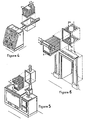
- Figure 1 is an open fire burning coal, wood, peat, gas (artificial logs or coal), and etc., with the unit Figure 3, fitted to the top of the open surround by a containment 19 and 20 - - figure 2 as if a drawer in its slider to a cabinet.
- Figure 4 shows a unit fitted to the after flue pipe of a closed fire.
- Figure 5 shows a unit fitted to the after flue pipe of a solid fuel, oil or gas fired cooker/boiler.
- Figure 6 shows a unit fitted to the flue pipe in the chimney breast above an open fire.
- a unit may or may not have a supply of ducted fresh air from the exterior supplied to the inlet 1 and a unit may or may not have air from outlet 2 ducted away to some distant use. All applications of the system dependant on the requirements of the user.
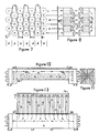
- FIG. 7 and Figure 8 shows banks of tubes A, B, C, D, E, F, through which may be forced air say from the room.
- the flow of the air through the unit is in the form of from the room 1 through the upper banks of tubes 6 down through the communicating chamber 7 and back along the lower banks of tubes 8 and return to the room 2.
- 25 is a separating membrane.
- Flue gases from the heat source (fire etc.) rise up through the array of tubes at F1 and exit at F2. As the flue gases travel through the banks of tubes they heat up these tubes which in turn pass their heat on to the air passing through the tubes, Figure 9.
- the passage of air through the tubes is in overall effect in reverse order to that of the passage of the flue gases. Cool room air entering the system meets cooled flue gases leaving the system in the upper banks of tubes. This room air is gradually heated as it passes through the system, the reverse being the case for the flue gases, and meets the hotter flue gases entering the system in the lower banks of tubes as it - the room air - then leaves this harmonious system.
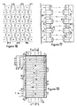
- Figures 10, 11, 12, and 13 depict a unit in schematic elevation, end view, partial cross section and plan view, which unit may be fitted to the upper part of the opening to an open fire (as depicted in Figures 1 and 3) with the containment unit depicted in Figure 14 and 15 (as depicted in Figure 2).
- Air is shown entering from the room 1 through a probable filter 3 and into the unit through the fan or fans 4, along a communication duct 5 and into the banks of tubes 6 ( Figure 12, one tube drawn for clarity) and into the comnunicating duct 7 and down and back along the banks of tubes 8 ( Figure 12, one tube drawn for clarity) and exiting into the room 2.
- the gauge thickness of the tube wall ( Figure 9) 26, in the two lower banks A and B are of equal gauge and of such thickness as to minimize their destruction from heat contact.
- the system may be further enhanced by the tubes in the upper banks above A and B being constructed of a gauge wall thickness lighter than that of tubes A and B and reducing in gauge wall thickness to the lightest being in the uppermost bank. This would have the effect of maximizing the rate of transfer of heat to the room air passing through the tubes which room air is quenching the inner wall of the tube of the heat conducted through the tube wall thickness. The net effect of this being maximum heat gain in the room air and maximum heat loss in the flue gases, i.e. maximum efficiency in the system.
- a unit may comprise any number of tubes from two upwards depending on the system required for a particular application.
- Figures 16 and 17 are further interpretations of the previously stated system whereby flue gases enter at F1 and exit at F2 through a greater number of tubes than depicted in Figure 7, with room air entering at 1 and flowing through tubes 6 into and down communicating duct 7 and through tubes 8 and down communicating duct 9 and through tubes 10 and down communicating duct 11 and through tubes 12 and exiting into the room 2.
- Figure 18 is a schematic elevation of Figures 16 and 17 with flue gases entering F1 and exiting F2 with room air entering at 1 and exiting at 2, for a possible installation to a chimney breast as depicted in Figure 6 with a plan view of the containment depicted in Figure 20, as 19, having flange 20 for bolting the unit in a gas proof seal, with the unit taking heat from the gases in a standard wall flue 21. Further adaptations of this unit are as previously stated - into an airing cupboard and/or another room and etc.
- Figure 19 is a schematic cross section of a possible system to a boiler or cooker or free standing heater as depicted in Figure 4 and 5 with further banks of tubes to previously stated, - through tubes 12 - and down communicating duct 13 and through tubes 14 and down communicating duct 15 and through tubes 16 and exiting into the room 2.
- the containment here is an open sided box 17 with flange 20 for gas proof seal and flue connector 18 at either end of the box for connection to after flue pipe of the heat source.
- a further adaptation may be as in Figure 1 where the fans housings 22 may be fitted at the bottoms of legs - as communicating ducts, vertically to and with duct 5, immediately in front of 23 - and thereby allowing the open fire to be increased in size forward of its original surround 23 and with a larger grate fitted forward of the original at 24.
- the unit is removable from its containment structure thereby providing accessibility for the cleaning of the flue and also the unit itself which may be immersed, e.g. in a bath of liquids capable of dissolving any solid matter adhering to the unit.
- the unit could be constructed of materials such as stainless steel for appearance and freedom of maintenance and, e.g. zinc galvanized or electroplated steel tubes etc, and which unit by its removability may be maintained by redipping etc, if required.
- Central heating is generally represented by radiators supplied with hot water from a boiler system through pipes, and over which radiators - should be referred to as convectors as radiation does not take place without a 200degC temperature difference between the radiator and the radiated - flows room air convecting away the heat to room furniture and etc, and generally raising room temperature.
- the cost of running a 100 CFM (47 ⁇ 10 ⁇ 3 [m3/s]) fan is 1 unit of electricity (6.38pence) per 40 Hrs, with a life expectancy of the fan between 25,000 - 30,000 Hrs (1250 days) continuous running.
- the apparatus as hereinbefore described provides filtered particle free air and heated (depending on the fire built up) to temperatures well in excess of 100degC, which intensely heated air within the unit provides a bacterium and virus destruct - the vast majority of these being destroyed at 121degC - environment, further benefiting the interior environment-of the home or workplace in providing all round warmth from an open fire - whereas without the apparatus ones front was warm and ones back was cold - and in providing a de-humidified (condensation loss), and well ventilated atmosphere.
- the heating apparatus of this invention operates in counter current fashion by moving air from a cooler more distant region of the heat flow path to a hotter region of the heat flow path nearer to the source of heat, it is to be understood that in other embodiments the apparatus may be arranged to utilize a temperature gradient existing across a heat flow path.
- the unit generally performed in the region of 80% efficiency, with the slight discrepancies in the test results due to the fluctuation of flame strength resulting from the burning of wood only, for the results obtained in all tests.
Landscapes
- Engineering & Computer Science (AREA)
- Chemical & Material Sciences (AREA)
- Combustion & Propulsion (AREA)
- Mechanical Engineering (AREA)
- General Engineering & Computer Science (AREA)
- Physics & Mathematics (AREA)
- Thermal Sciences (AREA)
- Air Supply (AREA)
- Resistance Heating (AREA)
- Heat-Exchange Devices With Radiators And Conduit Assemblies (AREA)
- Ventilation (AREA)
Claims (9)
- Vorrichtung zum Aufheizen einer Umgebung, bestehend aus einem Kasten (17,19), welcher eine Einlassöffnung (F₁) und eine Auslassöffnung (F₂) für Rauchgase aufweist und welcher einen Strömungsweg für die Rauchgase definiert, einer Vielzahl von in diesem Kasten und in Sätzen (A-F) angeordneten Wärmetauschkanälen (6,8), wobei die Sätze innerhalb des Kastens in beabstandeter Relation zueinander und in Strömungsrichtung der Rauchgase einer über dem anderen angeordnet sind, und wobei die Kanäle jedes Satzes im wesentlichen quer zu diesem Strömungsweg der Rauchgase angeordnet sind, und wobei diese Kanäle (6,8) mindestens einen Teil von mindestens einem Wärmetauscher bilden, der eine Einlassöffnung (1) und eine Auslassöffnung (2) für die beim Durchströmen der Kanalsätze aufzuheizende Luft aufweist, und Mittel (22) zur Förderung der Luftströmung aufweist, die mit den Wärmetauschern wirkverbunden sind, um Luft von der Einlassöffnung (1) zur Auslassöffnung (2) zu treiben,
dadurch gekennzeichnet, dass
eine Vielzahl von Kanälen (6,8) vorgesehen ist, die mindestens drei erste Sätze von parallel verlaufenden Rohren (6,10,14) umfassen, welche in den Rauchgasströmungsweg hineinragen, wobei die Einlassöffnungen dieser ersten Rohre mit den strömungsfördernden Mitteln (22) wirkverbunden sind und dass mindestens drei Sätze (8,12,16) von parallelen zweiten Rohren vorhanden sind, die direkt oder indirekt an die Auslassöffnungen der ersten Rohre angeschlossen sind und aus dem Rauchgasströmungsweg herausragen;
dass der Abstand zwischen den Kanalsätzen stromabwärts des erhitzten Rauchgases allmählich so verringert ist, dass der Durchlass für die Rauchgase progressiv abnimmt,
dass, während der Abstand der Sätze verringert ist, das Durchlassvolumen für die aufzuheizende Luft unverändert bleibt,
und dass die Reduktion des Durchlasses für die Rauchgase dergestalt ist, dass für ein unverändertes Volumen des Rauchgasstromes dessen Druck progressiv erhöht wird, wenn dieser von der Einlassöffnung (F₁) zur Auslassöffnung (F₂) des Kastens strömt, wobei stromabwärts diese Druckerhöhung der Rauchgase den Temperaturabfall derselben verringert, wodurch die Rate des Wärmeaustausches zwischen den Rauchgasen und der Luft verbessert ist. - Vorrichtung nach Patentanspruch 1, dadurch gekennzeichnet, dass die Kanäle jedes Satzes (6,10,14;8,12,16) so angeordnet sind, dass sie den Rauchgasstrom mindestens zweimal durchqueren.
- Vorrichtung nach einem der Ansprüche 1 oder 2, dadurch gekennzeichnet, dass die Kanäle jedes Satzes (6,10,14;8,12,16) eine sinusförmige Stromführung für die aufzuheizende Luft aufweisen.
- Vorrichtung nach einem der Ansprüche 1, 2 oder 3, dadurch gekennzeichnet, dass der Luftstrom in dem oder in jedem Kanal zweimal oder mehrmals seine Richtung ändert.
- Vorrichtung nach einem der Ansprüche 1 bis 4, dadurch gekennzeichnet, dass der oder die Kanäle eines Satzes als durchgehende Rohre ausgebildet sind.
- Vorrichtung nach einem der Ansprüche 1 bis 4, dadurch gekennzeichnet, dass der oder die Kanäle aus einer Folge von Rohren (6-10) besteht, welche mittels einer oder mehreren Plenumkammern (5,7;11,13) miteinander verbunden sind.
- Vorrichtung nach einem der vorgehenden Ansprüche, dadurch gekennzeichnet, dass die Wandstärke des oder jedes Wäremtauschkanals (6,10,14; 8,12,16) in einem stromabwärts gelegenen Teil des Rauchgasströmungsweges geringer ist als die Wandstärke in einem stromaufwärts gelegenen Teil des Rauchgasströmungsweges.
- Vorrichtung nach einem der vorgehenden Ansprüche, dadurch gekennzeichnet, dass die Vorrichtung sich zur Aufnahme von Luft aus einer Raumumgebung eignet.
- Vorrichtung nach einem der vorgehenden Ansprüche, dadurch gekennzeichnet, dass die Vorrichtung sich dazu eignet, aufzuheizende Luft aus einer Raumumgebung aufzunehmen und aufgeheizte Luft an eine andere Umgebung abzugeben.
Applications Claiming Priority (4)
| Application Number | Priority Date | Filing Date | Title |
|---|---|---|---|
| GB8628563 | 1986-11-28 | ||
| GB868628563A GB8628563D0 (en) | 1986-11-28 | 1986-11-28 | Convector heating apparatus |
| PCT/GB1987/000851 WO1988004014A1 (en) | 1986-11-28 | 1987-11-27 | Convector heating apparatus |
| CA000614752A CA1336807C (en) | 1986-11-28 | 1989-09-29 | Convector heating apparatus |
Publications (2)
| Publication Number | Publication Date |
|---|---|
| EP0333739A1 EP0333739A1 (de) | 1989-09-27 |
| EP0333739B1 true EP0333739B1 (de) | 1994-09-28 |
Family
ID=25673169
Family Applications (1)
| Application Number | Title | Priority Date | Filing Date |
|---|---|---|---|
| EP87907787A Expired - Lifetime EP0333739B1 (de) | 1986-11-28 | 1987-11-27 | Konvektorheizung |
Country Status (7)
| Country | Link |
|---|---|
| US (1) | US5046481A (de) |
| EP (1) | EP0333739B1 (de) |
| AT (1) | ATE112378T1 (de) |
| AU (1) | AU599186B2 (de) |
| CA (1) | CA1336807C (de) |
| DE (1) | DE3750611T2 (de) |
| WO (1) | WO1988004014A1 (de) |
Families Citing this family (32)
| Publication number | Priority date | Publication date | Assignee | Title |
|---|---|---|---|---|
| FR2633371B1 (fr) * | 1988-06-28 | 1993-07-02 | Morin Jean | Perfectionnements aux dispositifs de chauffage a air pulse pour cheminees a foyer ouvert |
| DK171668B1 (da) * | 1993-11-19 | 1997-03-10 | Ejner Bjoern Hansen | Apparatur til varmebehandling af et partikulært fødevareprodukt |
| GB9824532D0 (en) * | 1998-11-10 | 1999-01-06 | Colson Engineering Limited | Flame arrester |
| US6543698B1 (en) * | 2000-04-10 | 2003-04-08 | Heat-N-Glo Fireplace Products, Inc. | Fireplace make-up air heat exchange system |
| US6550687B2 (en) | 2000-04-10 | 2003-04-22 | Hon Technology Inc. | Heat exchange system |
| US6641970B2 (en) * | 2001-06-13 | 2003-11-04 | Agfa-Gevaert | UV-sensitive imaging element for making lithographic printing plates comprising an aryldiazosulfonate polymer and a compound sensitive to UV light |
| US6705310B2 (en) * | 2002-04-10 | 2004-03-16 | Cfm Corporation | Wood burner with improved emissions |
| DE10227626A1 (de) * | 2002-06-20 | 2004-01-15 | J. Eberspächer GmbH & Co. KG | Heizeinrichtung, insbesondere für ein Fahrzeug |
| US20080029613A1 (en) * | 2002-09-26 | 2008-02-07 | William Friedlich | Adjustable baseboard and molding system |
| US6883502B2 (en) | 2003-06-16 | 2005-04-26 | Caterpillar Inc. | Fluid/liquid heat exchanger with variable pitch liquid passageways and engine system using same |
| US20050199233A1 (en) * | 2004-03-12 | 2005-09-15 | Butler Gary L. | Fireplace hydronic heating |
| CA2488898C (en) * | 2004-06-01 | 2008-01-08 | Macpherson Engineering Inc. | Radiant heating system using forced air furnace as heat source |
| DE102004040662A1 (de) * | 2004-08-20 | 2006-02-23 | Alexander Biechteler | Verfahren und Vorrichtung zur Herstellung von expandierten Nahrungsmitteln |
| US20070169948A1 (en) | 2006-01-26 | 2007-07-26 | C. Cretors And Company | Fire containment system |
| GR1005490B (el) * | 2006-02-24 | 2007-04-12 | Συμεων Κατσανιδης | Κλωβος ανω τμηματος τζακιου υπερεκμεταλλευσης θερμοτητας |
| US20090126579A1 (en) * | 2007-11-19 | 2009-05-21 | Cretors Charles D | Popcorn machines and other machines having multiple heat zone cooking surfaces for producing popcorn and other types of expanded foods |
| US8201492B2 (en) * | 2008-03-07 | 2012-06-19 | C. Cretors & Company | Popcorn popping machines and associated methods of manufacture and use |
| US20110027434A1 (en) * | 2009-08-03 | 2011-02-03 | Cretors Charles D | Candy popcorn cooker and mixer, and associated methods of manufacture and use |
| US8794129B2 (en) * | 2009-09-25 | 2014-08-05 | C. Cretors & Company | System and methods for popping corn and producing other types of expanded foods |
| WO2011041271A1 (en) * | 2009-09-30 | 2011-04-07 | C. Cretors & Company | Popcorn machines and other machines having reversible food moving devices for popping popcorn and producing other types of expanded foods |
| WO2012145717A1 (en) | 2011-04-21 | 2012-10-26 | C. Cretors & Company | Popcorn popping machines and other machines having flow through decks for popping popcorn |
| US8978639B2 (en) * | 2011-10-14 | 2015-03-17 | Hearth & Home Technologies, Inc. | Secondary room air heat exchanger and method of heating secondary room air |
| US10631563B2 (en) | 2012-04-19 | 2020-04-28 | C. Cretors & Company | Popcorn machine having a filter passage inlet connected to a kettle assembly |
| WO2013159069A1 (en) | 2012-04-19 | 2013-10-24 | C. Cretors & Company | Air popcorn popper |
| US9943087B2 (en) | 2013-09-05 | 2018-04-17 | C. Cretors & Company | Multi-purpose kettles for producing caramel corn |
| CN207370067U (zh) | 2016-04-06 | 2018-05-18 | 茜·克里特斯公司 | 具有燃气辐射式燃烧器的爆米花机器及相关系统 |
| US10631562B2 (en) | 2016-11-23 | 2020-04-28 | C. Cretors & Company | Continuous popcorn machines having variable heating profiles and associated systems and methods |
| US11044929B2 (en) | 2016-12-16 | 2021-06-29 | C. Cretors & Company | Popcorn machines having process chambers of increasing volume, and associated systems and methods |
| WO2018206424A1 (en) * | 2017-05-10 | 2018-11-15 | Gea Food Solutions Weert B.V. | Improved heating means for a flow wrapper |
| CN209931412U (zh) | 2017-12-05 | 2020-01-14 | 茜·克里特斯公司 | 爆米花机 |
| US11930967B2 (en) | 2019-03-08 | 2024-03-19 | C. Cretors & Company | Food heaters, such as for use in heating hot dogs |
| US11172696B2 (en) | 2019-04-23 | 2021-11-16 | C. Cretors & Company | Popcorn machines having removable kettle assemblies |
Citations (1)
| Publication number | Priority date | Publication date | Assignee | Title |
|---|---|---|---|---|
| FR808092A (fr) * | 1936-07-10 | 1937-01-28 | Réchauffeur d'air |
Family Cites Families (17)
| Publication number | Priority date | Publication date | Assignee | Title |
|---|---|---|---|---|
| US193009A (en) * | 1877-07-10 | Improvement in sleeping-cars | ||
| US1334741A (en) * | 1918-07-29 | 1920-03-23 | Patrick F Dundon | Air-heating structure |
| US1627265A (en) * | 1926-11-20 | 1927-05-03 | Ingersoll Rand Co | Surface condenser |
| FR920812A (fr) * | 1945-10-12 | 1947-04-18 | Perfectionnements aux appareils pour le chauffage ou le refroidissement d'air à usages domestiques ou industriels | |
| GB569000A (en) * | 1946-01-18 | 1945-04-30 | Edward Frank Spanner | Improvements in tubes for heat exchange apparatus |
| FR929047A (fr) * | 1946-06-14 | 1947-12-15 | Perfectionnements aux moyens de chauffage des locaux | |
| US2613065A (en) * | 1947-11-21 | 1952-10-07 | Chausson Usines Sa | Cooling radiator |
| GB758247A (en) * | 1952-10-29 | 1956-10-03 | Newton Chambers & Co | Improvements to heat recuperators for furnaces |
| US2882023A (en) * | 1955-11-30 | 1959-04-14 | Home Heating Devices Inc | Heat economizer for small units |
| FR1328762A (fr) * | 1962-07-13 | 1963-05-31 | Grille de foyer permettant d'obtenir un double chauffage et améliorer le tirage | |
| DE2342787A1 (de) * | 1973-08-24 | 1975-03-06 | Kloeckner Humboldt Deutz Ag | Kreuzstromwaermetauscher, insbesondere ladeluftkuehler fuer aufgeladene brennkraftmaschinen |
| US3905351A (en) * | 1975-01-08 | 1975-09-16 | James M Hatfield | Fireplace heat distribution unit |
| JPS54109647A (en) * | 1978-02-17 | 1979-08-28 | Babcock Hitachi Kk | Wear preventive device for heat exchanging pipe |
| AU3611178A (en) * | 1978-05-15 | 1979-11-22 | Clarke B T | Fireplace heat saver |
| US4550772A (en) * | 1983-03-31 | 1985-11-05 | Knoch Darrell G | Heat recovery device for exhaust flues |
| AU587329B2 (en) * | 1986-12-20 | 1989-08-10 | William Roger Court | Domestic heat exchanger |
| US4805692A (en) * | 1987-03-10 | 1989-02-21 | Pure Water, Inc. | Condenser for water purification apparatus |
-
1987
- 1987-11-27 DE DE3750611T patent/DE3750611T2/de not_active Expired - Fee Related
- 1987-11-27 EP EP87907787A patent/EP0333739B1/de not_active Expired - Lifetime
- 1987-11-27 US US07/359,658 patent/US5046481A/en not_active Expired - Fee Related
- 1987-11-27 AT AT87907787T patent/ATE112378T1/de active
- 1987-11-27 WO PCT/GB1987/000851 patent/WO1988004014A1/en not_active Ceased
- 1987-11-27 AU AU83270/87A patent/AU599186B2/en not_active Ceased
-
1989
- 1989-09-29 CA CA000614752A patent/CA1336807C/en not_active Expired - Fee Related
Patent Citations (1)
| Publication number | Priority date | Publication date | Assignee | Title |
|---|---|---|---|---|
| FR808092A (fr) * | 1936-07-10 | 1937-01-28 | Réchauffeur d'air |
Also Published As
| Publication number | Publication date |
|---|---|
| DE3750611T2 (de) | 1995-05-04 |
| EP0333739A1 (de) | 1989-09-27 |
| CA1336807C (en) | 1995-08-29 |
| ATE112378T1 (de) | 1994-10-15 |
| US5046481A (en) | 1991-09-10 |
| AU599186B2 (en) | 1990-07-12 |
| AU8327087A (en) | 1988-06-16 |
| WO1988004014A1 (en) | 1988-06-02 |
| DE3750611D1 (de) | 1994-11-03 |
Similar Documents
| Publication | Publication Date | Title |
|---|---|---|
| EP0333739B1 (de) | Konvektorheizung | |
| US4050441A (en) | Grate and stove heating unit | |
| GB2448204A (en) | Heat exchanger with concentric hollow pipes and hot swirling gas | |
| US3926173A (en) | Furnace and cold air return systems | |
| CA1109349A (en) | Heat circulating fireplace | |
| US4033320A (en) | Furnace and cold air return systems | |
| US4050627A (en) | Adjustable heat recovery system for flue stacks | |
| US3274990A (en) | Mass-production low-cost furnace for supplying high-temperature highvelocity air fordomestic heating | |
| US4215669A (en) | Hot air furnace | |
| US4261323A (en) | Grate and stove heating unit | |
| EP3847396B1 (de) | Feuerstelle mit einem sicherheitsbarriere-wärmetauscher | |
| US2348569A (en) | Hot-air furnace | |
| US2391028A (en) | Hot air heating furnace | |
| US4106693A (en) | Automatic fireplace heating system | |
| US2225181A (en) | Heating and air conditioning unit | |
| US4524754A (en) | Heating appliance | |
| US4020823A (en) | Hot air heating system | |
| RU93002653A (ru) | Бытовой котел | |
| CA2869444C (en) | Thermal storage condensing boiler or heat exchanger | |
| RU226406U1 (ru) | Отопительная конвекционная печь | |
| US355208A (en) | Teeeitoey | |
| US939890A (en) | Stove. | |
| GB815308A (en) | Combined radiation and convector stove | |
| US1065074A (en) | Heating system. | |
| GB1578669A (en) | Space heating stoves |
Legal Events
| Date | Code | Title | Description |
|---|---|---|---|
| PUAI | Public reference made under article 153(3) epc to a published international application that has entered the european phase |
Free format text: ORIGINAL CODE: 0009012 |
|
| 17P | Request for examination filed |
Effective date: 19890529 |
|
| AK | Designated contracting states |
Kind code of ref document: A1 Designated state(s): AT BE CH DE FR GB IT LI LU NL SE |
|
| 17Q | First examination report despatched |
Effective date: 19901126 |
|
| GRAA | (expected) grant |
Free format text: ORIGINAL CODE: 0009210 |
|
| AK | Designated contracting states |
Kind code of ref document: B1 Designated state(s): AT BE CH DE FR GB IT LI LU NL SE |
|
| REF | Corresponds to: |
Ref document number: 112378 Country of ref document: AT Date of ref document: 19941015 Kind code of ref document: T |
|
| REF | Corresponds to: |
Ref document number: 3750611 Country of ref document: DE Date of ref document: 19941103 |
|
| PGFP | Annual fee paid to national office [announced via postgrant information from national office to epo] |
Ref country code: NL Payment date: 19941130 Year of fee payment: 8 |
|
| PGFP | Annual fee paid to national office [announced via postgrant information from national office to epo] |
Ref country code: LU Payment date: 19941201 Year of fee payment: 8 |
|
| PGFP | Annual fee paid to national office [announced via postgrant information from national office to epo] |
Ref country code: FR Payment date: 19941214 Year of fee payment: 8 |
|
| PGFP | Annual fee paid to national office [announced via postgrant information from national office to epo] |
Ref country code: DE Payment date: 19941215 Year of fee payment: 8 |
|
| PGFP | Annual fee paid to national office [announced via postgrant information from national office to epo] |
Ref country code: GB Payment date: 19941219 Year of fee payment: 8 |
|
| PGFP | Annual fee paid to national office [announced via postgrant information from national office to epo] |
Ref country code: SE Payment date: 19941221 Year of fee payment: 8 |
|
| ITF | It: translation for a ep patent filed | ||
| PGFP | Annual fee paid to national office [announced via postgrant information from national office to epo] |
Ref country code: BE Payment date: 19950104 Year of fee payment: 8 |
|
| PGFP | Annual fee paid to national office [announced via postgrant information from national office to epo] |
Ref country code: AT Payment date: 19950130 Year of fee payment: 8 |
|
| EAL | Se: european patent in force in sweden |
Ref document number: 87907787.3 |
|
| ET | Fr: translation filed | ||
| PGFP | Annual fee paid to national office [announced via postgrant information from national office to epo] |
Ref country code: CH Payment date: 19950222 Year of fee payment: 8 |
|
| PLBE | No opposition filed within time limit |
Free format text: ORIGINAL CODE: 0009261 |
|
| STAA | Information on the status of an ep patent application or granted ep patent |
Free format text: STATUS: NO OPPOSITION FILED WITHIN TIME LIMIT |
|
| 26N | No opposition filed | ||
| PG25 | Lapsed in a contracting state [announced via postgrant information from national office to epo] |
Ref country code: LU Free format text: LAPSE BECAUSE OF NON-PAYMENT OF DUE FEES Effective date: 19951127 Ref country code: GB Effective date: 19951127 Ref country code: AT Effective date: 19951127 |
|
| PG25 | Lapsed in a contracting state [announced via postgrant information from national office to epo] |
Ref country code: SE Effective date: 19951128 |
|
| PG25 | Lapsed in a contracting state [announced via postgrant information from national office to epo] |
Ref country code: LI Effective date: 19951130 Ref country code: CH Effective date: 19951130 Ref country code: BE Effective date: 19951130 |
|
| BERE | Be: lapsed |
Owner name: WARWICK DEAN MABIN Effective date: 19951130 |
|
| PG25 | Lapsed in a contracting state [announced via postgrant information from national office to epo] |
Ref country code: NL Effective date: 19960601 |
|
| REG | Reference to a national code |
Ref country code: CH Ref legal event code: PL |
|
| GBPC | Gb: european patent ceased through non-payment of renewal fee |
Effective date: 19951127 |
|
| PG25 | Lapsed in a contracting state [announced via postgrant information from national office to epo] |
Ref country code: FR Effective date: 19960731 |
|
| NLV4 | Nl: lapsed or anulled due to non-payment of the annual fee |
Effective date: 19960601 |
|
| PG25 | Lapsed in a contracting state [announced via postgrant information from national office to epo] |
Ref country code: DE Effective date: 19960801 |
|
| EUG | Se: european patent has lapsed |
Ref document number: 87907787.3 |
|
| REG | Reference to a national code |
Ref country code: FR Ref legal event code: ST |
|
| PG25 | Lapsed in a contracting state [announced via postgrant information from national office to epo] |
Ref country code: IT Free format text: LAPSE BECAUSE OF NON-PAYMENT OF DUE FEES;WARNING: LAPSES OF ITALIAN PATENTS WITH EFFECTIVE DATE BEFORE 2007 MAY HAVE OCCURRED AT ANY TIME BEFORE 2007. THE CORRECT EFFECTIVE DATE MAY BE DIFFERENT FROM THE ONE RECORDED. Effective date: 20051127 |