EP0333579A1 - Befestigungssystem für Fahrzeugarmaturenbrett - Google Patents
Befestigungssystem für Fahrzeugarmaturenbrett Download PDFInfo
- Publication number
- EP0333579A1 EP0333579A1 EP89400700A EP89400700A EP0333579A1 EP 0333579 A1 EP0333579 A1 EP 0333579A1 EP 89400700 A EP89400700 A EP 89400700A EP 89400700 A EP89400700 A EP 89400700A EP 0333579 A1 EP0333579 A1 EP 0333579A1
- Authority
- EP
- European Patent Office
- Prior art keywords
- ring
- accessory
- support plate
- dashboard according
- hook structures
- Prior art date
- Legal status (The legal status is an assumption and is not a legal conclusion. Google has not performed a legal analysis and makes no representation as to the accuracy of the status listed.)
- Granted
Links
Images


Classifications
-
- B—PERFORMING OPERATIONS; TRANSPORTING
- B60—VEHICLES IN GENERAL
- B60K—ARRANGEMENT OR MOUNTING OF PROPULSION UNITS OR OF TRANSMISSIONS IN VEHICLES; ARRANGEMENT OR MOUNTING OF PLURAL DIVERSE PRIME-MOVERS IN VEHICLES; AUXILIARY DRIVES FOR VEHICLES; INSTRUMENTATION OR DASHBOARDS FOR VEHICLES; ARRANGEMENTS IN CONNECTION WITH COOLING, AIR INTAKE, GAS EXHAUST OR FUEL SUPPLY OF PROPULSION UNITS IN VEHICLES
- B60K35/00—Instruments specially adapted for vehicles; Arrangement of instruments in or on vehicles
- B60K35/50—Instruments characterised by their means of attachment to or integration in the vehicle
Definitions
- the present invention relates to the field of motor vehicle dashboards.
- the present invention aims to provide a system for attaching accessories, such as measuring movements or indicators, on a support plate of a dashboard of a motor vehicle, by automatic assembly.
- Another object of the present invention is to provide a system for fixing the aforementioned accessories in a removable manner.
- Another object of the present invention is to provide a system allowing the accessories to be fixed elastically, that is to say to avoid any vibration of the latter in use.
- An auxiliary object of the present invention is to propose a system making it possible to fix simultaneously on the support plate of a dashboard of a motor vehicle, an accessory, such as a measuring movement or display, and an associated light guide.
- the accessories are currently fixed to the support plates of dashboards of a motor vehicle, by gluing, or using rivets or screws.
- these means are entirely satisfactory. Bonding is difficult to use in mass production and moreover does not allow disassembly. Likewise, the rivets do not use disassembly. Finally, the screws are difficult to implement in an automatic assembly cycle and relatively expensive.
- the present invention improves the situation by proposing a system responding to the aforementioned bits which comprises: - a support plate provided with at least two hook structures on a common face, - at least one accessory comprising a body provided with at least two protrusions projecting from its external surface, and - a retaining ring adapted to be engaged in the hook structures, which has an internal channel greater than the section of the body and smaller than the external size of the protuberances provided thereon to resiliently hold the accessory against the support plate when the ring is engaged in the hook structures.
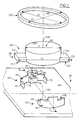
- the system according to the present invention comprises a support plate 100, at least one accessory 200 and a retaining ring 300.
- the support plate 100 is provided with at least two hook structures 110, 130. These are formed projecting from a common face 101 of the support plate and substantially diametrically opposite to an axis 102 of the system which extends perpendicular to the support plate 100.
- the hook structures 110, 130 are formed by walls 111, 131 which extend perpendicular to the support plate 100. According to the illustration given in the figure, the walls 111, 131, are formed by cylinder sectors centered on the 'axis 102 above.
- the low walls 111, 131 are provided near their free edges distant from the surface 101 of the support plate 100 and on their surfaces 112, 132, respectively opposite and directed towards the axis 102, of teeth 113, 133.
- each teeth 113, 133 which are directed towards the surface 101 of the support plate, extend substantially parallel to this surface 101.
- the lower surfaces 114 and 134 of the teeth 113 and 133 are generally coplanar.
- the upper surfaces 115 and 135 of the teeth 113, 133 which are directed opposite the surface 101 of the support plate, are not parallel to this surface 101 but converge towards this surface 101.
- the surfaces upper 115, 135, teeth 113, 133 moreover extend the upper surface of the walls 111, 131, to define engagement edges facilitating the insertion of the ring 300 under the teeth 113, 133, as will be indicated below.
- One of the hook structures 110 is provided with an opening 116, making it possible to exert a radial force on the ring 300 when the latter is engaged under the teeth 113, 133. More precisely, the opening 116 is formed in the wall 111. It is oriented radially with respect to the axis 102 and extends in the wall 111 between the surface 101 of the support plate 100 and the lower surface 114 of the toothing 113.
- the walls 111, 131 are provided with fabrics 117, 118, 119, 137, 138, 139. These fabrics are directed substantially towards the axis 102. They naturally have a height, relative to the surface 101 of the support plate 100, less than the distance separating the surface 101 of the support plate, from the lower surface 114, 134 of the teeth 113, 133.
- a fabric 117, 118 and 137, 138 is thus provided at each of the lateral ends of the walls 111, 131, on the one hand, and a canvas 119, 139, substantially mid-length of the walls 111, 131, on the other hand.
- the central fabrics 119, 139 preferably have a cross section generally in a "U" shape and surround openings 120, 130, formed in the support plate 100 opposite the lower surfaces 114, 134, teeth 113, 133. These openings 120 , 130, are intended to allow the passage of movable inserts allowing the production of the entire support plate by plastic molding.
- the accessory 200 illustrated in FIG. 1 comprises a body 201 having an axis 202 and two protrusions 210, 220, projecting from the outer periphery of the body 201 and substantially diametrically opposite with respect to the axis 202.
- the protrusions 210, 220 are delimited by lower surfaces 211, 221, and upper 212, 222, which extend perpendicular to the axis 202 and are respectively coplanar two by two.
- the body 201 has a generally cylindrical envelope of revolution around the axis 202.
- this geometry is not limiting. It is simply necessary for the cross section of the body 201 to be less than the free space between the hook structures 110, 130, in order to place the accessory 200 between these structures, in contact with the surface 101 of the support plate 100.
- the ring 300 illustrated in the appended figures is centered on an axis 302.
- the retaining ring 300 can be made of metal or plastic.
- the internal diameter D1 of the ring 300 must be greater than the largest dimension L1 of the body 201 transverse to the axis 202 to allow engagement of the ring 300 on the periphery of the body 201.
- the internal diameter D1 of the ring 300 must be less than the external dimensions L2 of the protrusions 210, 220, considered transversely to the axis 202.
- the ring 300 rests on the upper surface 212, 222 protrusions 210 and 220 when it is engaged on the periphery of the body 201.
- the outside radius of the retaining ring 300 which corresponds to half of the outside diameter D2, can be substantially equal, while remaining slightly smaller, to the radius of the walls 111, 131.
- the ring 300 can be resiliently engaged under the teeth 113, 133.
- the support plate 100 may be provided with a through opening 150 centered on the axis 102, to allow the passage of electrical connections 203 ensuring the supply of the accessory 200 or an output axis of the 'accessory.
- a stop 400 can be interposed between the accessory 300 and the surface 101 of the support plate 100.
- the stop 400 can be formed of a washer having substantially the same section as the body 201.
- the stop 400 interposed between the accessory 200 and the surface 101 can be replaced or associated with a light guide 401 making it possible to illuminate an element of the accessory 200, for example a needle, using a light source 402 distant from the accessory and placed opposite guide 401.
- the use of such an optical guide 401 to illuminate an accessory 200 is known per se and will therefore not be described in more detail below.
- this stop 400 and / or this optical guide 401 can be provided ) a bore 403 aligned with the bore 150 to allow the passage of electrical connections 203 or an outlet axis of the accessory.
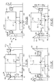
- FIGS. 3A, 3B, 3C and 3D The assembly of the accessory 200 using the system according to the invention is illustrated in FIGS. 3A, 3B, 3C and 3D.
- the accessory 200 is placed between the hook structures 110, 130, if necessary, after having inserted a stop 400 or an optical guide 401.
- the ring 300 is engaged on the body 201. Initially, it comes to rest against the converging engagement surfaces 115, 135. in this position the axes 102, 202 and 302 mentioned above are generally coaxial.
- the ring 300 thus comes to bear against the upper surfaces 212 and 202 of the protrusions 210, 220.
- the immobilization of the accessory 200 is carried out when the ring 300 reaches the lower surfaces 114, 134, of the teeth 113, 133.
- the ring 300 then resumes a generally circular shape to come to engage under the teeth bearing against the lower surfaces 114, 134 thereof.
- Such an assembly can easily be provided automatically. It will however be noted that, in the context of the present invention, to guarantee perfect attachment of the accessory 200, free of vibration, the engagement of the ring 300 under the teeth 113, 133, as illustrated in FIG. 3D, is produced only after coming into abutment against the upper surfaces 212, 222 of the protrusions 210, 220, and therefore only after deformation of the ring 300 perpendicular to its mean plane transverse to the axis 202.
- the retaining ring 300 may be integral with auxiliary elements.
- the ring 300 can be made integral, by means of flexible tabs 304, with a plate 306 made of electrically insulating material.
- Such a plate 306 can be intended to rest against the rear face 203 of the body 201 to provide electrical insulation between the housing or body 201 and electrical contacts supplying the accessory 200.
- the plate 306 can be provided with bores 308 to this effect to allow passage of the aforementioned electrical contacts.
- the ring 300, the plate and the tabs 304 can be made of plastic in one piece.
- the ring 300 associated with the plate 306, can be prepositioned on the body 201 of the accessory. This arrangement facilitates the mounting of the system.
Landscapes
- Engineering & Computer Science (AREA)
- Chemical & Material Sciences (AREA)
- Combustion & Propulsion (AREA)
- Transportation (AREA)
- Mechanical Engineering (AREA)
- Connection Of Plates (AREA)
Applications Claiming Priority (2)
| Application Number | Priority Date | Filing Date | Title |
|---|---|---|---|
| FR8803380A FR2628798B1 (fr) | 1988-03-16 | 1988-03-16 | Tableau de bord de vehicule automobile |
| FR8803380 | 1988-03-16 |
Publications (2)
| Publication Number | Publication Date |
|---|---|
| EP0333579A1 true EP0333579A1 (de) | 1989-09-20 |
| EP0333579B1 EP0333579B1 (de) | 1993-01-27 |
Family
ID=9364304
Family Applications (1)
| Application Number | Title | Priority Date | Filing Date |
|---|---|---|---|
| EP89400700A Expired - Lifetime EP0333579B1 (de) | 1988-03-16 | 1989-03-14 | Befestigungssystem für Fahrzeugarmaturenbrett |
Country Status (3)
| Country | Link |
|---|---|
| EP (1) | EP0333579B1 (de) |
| DE (1) | DE68904579T2 (de) |
| FR (1) | FR2628798B1 (de) |
Cited By (2)
| Publication number | Priority date | Publication date | Assignee | Title |
|---|---|---|---|---|
| FR2675746A1 (fr) * | 1991-04-25 | 1992-10-30 | Sagem | Face avant de montage d'instruments de bord, notamment pour vehicule automobile. |
| WO2003005781A3 (de) * | 2001-06-30 | 2003-04-10 | Siemens Ag | Mittel zum verbinden einer frontblende eines quaderförmigen einbaugerätes mit dessen einbaugehäuseteil |
Citations (5)
| Publication number | Priority date | Publication date | Assignee | Title |
|---|---|---|---|---|
| FR535518A (fr) * | 1920-05-20 | 1922-04-15 | Dispositif d'assemblage à baïonnette pour fixer dans une cage formant support, un instrument comportant une lunette vissée sur la carrure de la boîte, tel qu'une pièce d'horlogerie | |
| GB492686A (en) * | 1937-03-25 | 1938-09-26 | Oliver Edwin Simmonds | An improved fastening device incorporating a nut |
| FR1396724A (fr) * | 1964-05-13 | 1965-04-23 | Mécanisme de montage | |
| US3537499A (en) * | 1967-08-16 | 1970-11-03 | Standard Pressed Steel Co | Floating fastener unit |
| GB1386408A (en) * | 1971-03-20 | 1975-03-05 | Lucas Industries Ltd | Lighting arrangements for panels |
-
1988
- 1988-03-16 FR FR8803380A patent/FR2628798B1/fr not_active Expired - Lifetime
-
1989
- 1989-03-14 DE DE8989400700T patent/DE68904579T2/de not_active Expired - Fee Related
- 1989-03-14 EP EP89400700A patent/EP0333579B1/de not_active Expired - Lifetime
Patent Citations (5)
| Publication number | Priority date | Publication date | Assignee | Title |
|---|---|---|---|---|
| FR535518A (fr) * | 1920-05-20 | 1922-04-15 | Dispositif d'assemblage à baïonnette pour fixer dans une cage formant support, un instrument comportant une lunette vissée sur la carrure de la boîte, tel qu'une pièce d'horlogerie | |
| GB492686A (en) * | 1937-03-25 | 1938-09-26 | Oliver Edwin Simmonds | An improved fastening device incorporating a nut |
| FR1396724A (fr) * | 1964-05-13 | 1965-04-23 | Mécanisme de montage | |
| US3537499A (en) * | 1967-08-16 | 1970-11-03 | Standard Pressed Steel Co | Floating fastener unit |
| GB1386408A (en) * | 1971-03-20 | 1975-03-05 | Lucas Industries Ltd | Lighting arrangements for panels |
Cited By (3)
| Publication number | Priority date | Publication date | Assignee | Title |
|---|---|---|---|---|
| FR2675746A1 (fr) * | 1991-04-25 | 1992-10-30 | Sagem | Face avant de montage d'instruments de bord, notamment pour vehicule automobile. |
| WO2003005781A3 (de) * | 2001-06-30 | 2003-04-10 | Siemens Ag | Mittel zum verbinden einer frontblende eines quaderförmigen einbaugerätes mit dessen einbaugehäuseteil |
| US7575204B2 (en) | 2001-06-30 | 2009-08-18 | Siemens Aktiengesellschaft | Arrangement for connecting a device's front panel |
Also Published As
| Publication number | Publication date |
|---|---|
| FR2628798B1 (fr) | 1990-08-24 |
| DE68904579D1 (de) | 1993-03-11 |
| DE68904579T2 (de) | 1993-08-12 |
| FR2628798A1 (fr) | 1989-09-22 |
| EP0333579B1 (de) | 1993-01-27 |
Similar Documents
| Publication | Publication Date | Title |
|---|---|---|
| FR2781259A1 (fr) | Cylindre hydraulique | |
| FR2808483A1 (fr) | Dispositif de reglage motorise pour siege de vehicule | |
| EP1703188A1 (de) | Halteschelle | |
| FR2956255A1 (fr) | Dispositif anti-deverrouillage pour connecteur | |
| EP0511105A1 (de) | Walzenlager mit Geschwindigkeitsmessaufnehmer | |
| EP0333579B1 (de) | Befestigungssystem für Fahrzeugarmaturenbrett | |
| FR2605742A1 (fr) | Generatrice tachymetrique | |
| EP1336763B1 (de) | Befestigungsmittel mit Klammer | |
| WO2004083657A1 (fr) | Dispositif de fixation a pince | |
| FR2547452A1 (fr) | Garniture de traversee de paroi pour cable electrique | |
| EP3668286A1 (de) | Abdichtsystem für elektrisches gerät | |
| EP0744088A1 (de) | Elektrische stecker in englischer ausführung | |
| FR2766299A3 (fr) | Element de connexion electrique, en particulier pour les cablages des detecteurs d'usure des plaquettes de frein | |
| EP0634586A1 (de) | Endstück für einen Reibbelagverschleisssensor, insbesondere für Bremsbeläge | |
| FR2968369A1 (fr) | Dispositif de cage pour un ecrou susceptible d'etre visse sur une vis | |
| EP0706915B1 (de) | Montage-Einrichtung für ein Bündel elektrischer Leiter | |
| FR2707002A1 (en) | Improved screened electrical sensor | |
| EP0703371B1 (de) | Vorrichtung zur Befestigung einer Anordnung an einer Säule, insbesondere für die Befestigung einer elektrischen Schaltvorrichtung an einer Kraftfahrzeuglenksäule | |
| BE1000787A6 (fr) | Groupe de branchement d'une lampe de signalisation. | |
| FR2851215A1 (fr) | Dispositif d'alimentation pour systeme de freinage, notamment pour vehicule automobile et procede de montage d'un tel systeme | |
| FR3000307A1 (fr) | Embout d'entree de conducteurs electriques dans une boite electrique | |
| FR2623857A1 (fr) | Dispositif de fixation pour tubulure ou analogue | |
| FR2708056A1 (fr) | Dispositif d'encliquetage, et ensemble ainsi équipé, notamment dans une unité de ventilation, chauffage et/ou climatisation pour automobile. | |
| EP0172779A1 (de) | Mehrpoliger elektrischer Verbinder | |
| FR2640049A1 (fr) | Capteur electromagnetique a reluctance variable et procede d'assemblage d'un tel capteur |
Legal Events
| Date | Code | Title | Description |
|---|---|---|---|
| PUAI | Public reference made under article 153(3) epc to a published international application that has entered the european phase |
Free format text: ORIGINAL CODE: 0009012 |
|
| AK | Designated contracting states |
Kind code of ref document: A1 Designated state(s): DE ES GB IT |
|
| 17P | Request for examination filed |
Effective date: 19891023 |
|
| 17Q | First examination report despatched |
Effective date: 19910715 |
|
| RTI1 | Title (correction) | ||
| RTI1 | Title (correction) | ||
| GRAA | (expected) grant |
Free format text: ORIGINAL CODE: 0009210 |
|
| AK | Designated contracting states |
Kind code of ref document: B1 Designated state(s): DE ES GB IT |
|
| PG25 | Lapsed in a contracting state [announced via postgrant information from national office to epo] |
Ref country code: IT Free format text: LAPSE BECAUSE OF FAILURE TO SUBMIT A TRANSLATION OF THE DESCRIPTION OR TO PAY THE FEE WITHIN THE PRESCRIBED TIME-LIMIT;WARNING: LAPSES OF ITALIAN PATENTS WITH EFFECTIVE DATE BEFORE 2007 MAY HAVE OCCURRED AT ANY TIME BEFORE 2007. THE CORRECT EFFECTIVE DATE MAY BE DIFFERENT FROM THE ONE RECORDED. Effective date: 19930127 Ref country code: ES Free format text: THE PATENT HAS BEEN ANNULLED BY A DECISION OF A NATIONAL AUTHORITY Effective date: 19930127 Ref country code: GB Effective date: 19930127 |
|
| REF | Corresponds to: |
Ref document number: 68904579 Country of ref document: DE Date of ref document: 19930311 |
|
| GBV | Gb: ep patent (uk) treated as always having been void in accordance with gb section 77(7)/1977 [no translation filed] |
Effective date: 19930127 |
|
| PLBE | No opposition filed within time limit |
Free format text: ORIGINAL CODE: 0009261 |
|
| STAA | Information on the status of an ep patent application or granted ep patent |
Free format text: STATUS: NO OPPOSITION FILED WITHIN TIME LIMIT |
|
| 26N | No opposition filed | ||
| PGFP | Annual fee paid to national office [announced via postgrant information from national office to epo] |
Ref country code: DE Payment date: 19990317 Year of fee payment: 11 |
|
| PG25 | Lapsed in a contracting state [announced via postgrant information from national office to epo] |
Ref country code: DE Free format text: LAPSE BECAUSE OF NON-PAYMENT OF DUE FEES Effective date: 20010103 |