EP0511105A1 - Walzenlager mit Geschwindigkeitsmessaufnehmer - Google Patents
Walzenlager mit Geschwindigkeitsmessaufnehmer Download PDFInfo
- Publication number
- EP0511105A1 EP0511105A1 EP92401161A EP92401161A EP0511105A1 EP 0511105 A1 EP0511105 A1 EP 0511105A1 EP 92401161 A EP92401161 A EP 92401161A EP 92401161 A EP92401161 A EP 92401161A EP 0511105 A1 EP0511105 A1 EP 0511105A1
- Authority
- EP
- European Patent Office
- Prior art keywords
- cage
- support
- bearing according
- groove
- bearing
- Prior art date
- Legal status (The legal status is an assumption and is not a legal conclusion. Google has not performed a legal analysis and makes no representation as to the accuracy of the status listed.)
- Granted
Links
Images


Classifications
-
- F—MECHANICAL ENGINEERING; LIGHTING; HEATING; WEAPONS; BLASTING
- F16—ENGINEERING ELEMENTS AND UNITS; GENERAL MEASURES FOR PRODUCING AND MAINTAINING EFFECTIVE FUNCTIONING OF MACHINES OR INSTALLATIONS; THERMAL INSULATION IN GENERAL
- F16C—SHAFTS; FLEXIBLE SHAFTS; ELEMENTS OR CRANKSHAFT MECHANISMS; ROTARY BODIES OTHER THAN GEARING ELEMENTS; BEARINGS
- F16C33/00—Parts of bearings; Special methods for making bearings or parts thereof
- F16C33/72—Sealings
- F16C33/76—Sealings of ball or roller bearings
- F16C33/78—Sealings of ball or roller bearings with a diaphragm, disc, or ring, with or without resilient members
-
- F—MECHANICAL ENGINEERING; LIGHTING; HEATING; WEAPONS; BLASTING
- F16—ENGINEERING ELEMENTS AND UNITS; GENERAL MEASURES FOR PRODUCING AND MAINTAINING EFFECTIVE FUNCTIONING OF MACHINES OR INSTALLATIONS; THERMAL INSULATION IN GENERAL
- F16C—SHAFTS; FLEXIBLE SHAFTS; ELEMENTS OR CRANKSHAFT MECHANISMS; ROTARY BODIES OTHER THAN GEARING ELEMENTS; BEARINGS
- F16C41/00—Other accessories, e.g. devices integrated in the bearing not relating to the bearing function as such
- F16C41/007—Encoders, e.g. parts with a plurality of alternating magnetic poles
-
- G—PHYSICS
- G01—MEASURING; TESTING
- G01P—MEASURING LINEAR OR ANGULAR SPEED, ACCELERATION, DECELERATION, OR SHOCK; INDICATING PRESENCE, ABSENCE, OR DIRECTION, OF MOVEMENT
- G01P3/00—Measuring linear or angular speed; Measuring differences of linear or angular speeds
- G01P3/42—Devices characterised by the use of electric or magnetic means
- G01P3/44—Devices characterised by the use of electric or magnetic means for measuring angular speed
- G01P3/443—Devices characterised by the use of electric or magnetic means for measuring angular speed mounted in bearings
-
- B—PERFORMING OPERATIONS; TRANSPORTING
- B60—VEHICLES IN GENERAL
- B60G—VEHICLE SUSPENSION ARRANGEMENTS
- B60G2204/00—Indexing codes related to suspensions per se or to auxiliary parts
- B60G2204/10—Mounting of suspension elements
- B60G2204/11—Mounting of sensors thereon
-
- B—PERFORMING OPERATIONS; TRANSPORTING
- B60—VEHICLES IN GENERAL
- B60G—VEHICLE SUSPENSION ARRANGEMENTS
- B60G2204/00—Indexing codes related to suspensions per se or to auxiliary parts
- B60G2204/10—Mounting of suspension elements
- B60G2204/11—Mounting of sensors thereon
- B60G2204/115—Wheel hub bearing sensors
-
- B—PERFORMING OPERATIONS; TRANSPORTING
- B60—VEHICLES IN GENERAL
- B60G—VEHICLE SUSPENSION ARRANGEMENTS
- B60G2204/00—Indexing codes related to suspensions per se or to auxiliary parts
- B60G2204/40—Auxiliary suspension parts; Adjustment of suspensions
- B60G2204/418—Bearings, e.g. ball or roller bearings
-
- B—PERFORMING OPERATIONS; TRANSPORTING
- B60—VEHICLES IN GENERAL
- B60G—VEHICLE SUSPENSION ARRANGEMENTS
- B60G2400/00—Indexing codes relating to detected, measured or calculated conditions or factors
- B60G2400/20—Speed
- B60G2400/208—Speed of wheel rotation
-
- F—MECHANICAL ENGINEERING; LIGHTING; HEATING; WEAPONS; BLASTING
- F16—ENGINEERING ELEMENTS AND UNITS; GENERAL MEASURES FOR PRODUCING AND MAINTAINING EFFECTIVE FUNCTIONING OF MACHINES OR INSTALLATIONS; THERMAL INSULATION IN GENERAL
- F16C—SHAFTS; FLEXIBLE SHAFTS; ELEMENTS OR CRANKSHAFT MECHANISMS; ROTARY BODIES OTHER THAN GEARING ELEMENTS; BEARINGS
- F16C19/00—Bearings with rolling contact, for exclusively rotary movement
- F16C19/02—Bearings with rolling contact, for exclusively rotary movement with bearing balls essentially of the same size in one or more circular rows
- F16C19/04—Bearings with rolling contact, for exclusively rotary movement with bearing balls essentially of the same size in one or more circular rows for radial load mainly
- F16C19/06—Bearings with rolling contact, for exclusively rotary movement with bearing balls essentially of the same size in one or more circular rows for radial load mainly with a single row or balls
Definitions
- the present invention relates to the field of bearings incorporating speed sensors.
- Such devices combining rolling and tachometric sensor can be used in any system comprising two parts in relative rotation, to control the relative movement of these.
- the present invention relates particularly to the field of motor vehicles.
- the present invention is not however limited to this particular use and can find application in the control of any system comprising two parts susceptible of relative rotation.
- the present invention aims to improve existing devices.
- a main object of the present invention is to provide means for simple mounting of the tachometer sensor on the bearing.
- An auxiliary object of the present invention is to propose means authorizing the phenomenon known as crawling. This will be explained later.
- Another auxiliary object of the present invention is to propose means allowing a simple angular adjustment of the sensor.
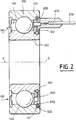
- a bearing comprising in a manner known per se an external cage, an internal cage and rolling bodies distributed between the external cage and the internal cage, characterized in that one of the cages comprises an annular groove, and that the bearing further comprises an annular support carrying a sensor and provided with a peripheral annular groove, and a segment capable of interfering with the annular groove and the annular groove to immobilize the translational sensor support on the bearing cage, while allowing relative rotation between them.
- the rolling bodies 150 are balls.
- the invention is however not limited to this particular embodiment.
- the rolling bodies can be formed from any structure known to those skilled in the art. They may, for example, be cylindrical bodies of constant section or frustoconical bodies arranged in one or more rows.
- the axis of rotation of the bearing is referenced O-O.
- a lubrication fluid most often grease
- This space 140 must therefore be closed and sealed. by seal structures placed between the outer cage 100 and the inner cage 120, on either side of the rolling bodies 150.
- one of the cages more specifically the external cage 100 according to the representation given in the appended figures, comprises a groove 110 capable of receiving the segment 300.
- the groove 110 is provided on the inner periphery 102 of the outer cage 100 and directed towards the axis of rotation OO.
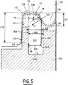
- the groove 110 is a groove with divergent walls. More specifically, according to the representation given in the appended figures, the groove 110 is delimited by an axially internal side wall 112, by an axially external side wall 114 and by a bottom wall 116.
- the first wall 112, axially internal, is generally planar and essentially perpendicular to the axis O-O of rotation of the bearing. If necessary, this first side wall 112, axially internal, delimiting the groove 110, can be slightly inclined on the axis of rotation O-O, in the direction of the center of the bearing in the direction of approximation of the axis O-O.
- the second wall 114 is on the contrary strongly inclined on the axis O-O. It diverges with respect to the first wall 112 above mentioned in approaching the axis O-O. In other words, the second wall 114, axially external, is inclined in the direction of the outside of the bearing in the direction of approximation of the axis O-O.
- the second wall 114 axially external, can be flat or generally rounded without discontinuity.
- the second side wall 114 typically has an average inclination of the order of 60 ° relative to the axis O-O.
- the bottom 116 of the groove 110 is generally plane and parallel to the axis O-O. It is connected respectively to the first axially internal lateral wall 112 and to the second axially external lateral wall 114 by concave rounded zones referenced 113 and 115 respectively in FIG. 5.
- the radial extension L112 of the above-mentioned first side wall 112 is much greater than the radial extension L114 of the above-mentioned second side wall 114.
- the second wall 114 delimiting the groove 110 is formed by a lip 118 projecting from the internal periphery of the cage 100, in the direction of the axis OO and which has a radial extension L114 less than the extension radial L112 of the first side wall 112.
- the outer surface 119 of this lip 108 is rounded convex, to facilitate the penetration of the segment 300 into the groove 110.
- the axial component F1 of this force F2 makes it possible to press an annular bearing surface 210 formed on the support 200 against the first side wall 112, to guarantee the sealing of the bearing and to avoid any vibration of the support 200.
- the support 200 is essentially formed of an annular structure centered on the axis O-O of rotation of the bearing. Its radial dimensions are adapted to the space 140 formed between the cage 100 and the internal cage 120, so that the support 200 can be placed between them.
- the peripheral radially external surface of the support 200 being preferably stepped, this radially external peripheral surface of the support 200 is generally complementary to the radially internal peripheral surface of the external cage 100.
- the radially peripheral surface the internal of the support 200 must be adapted to the radially external peripheral surface of the internal cage 120.
- the support 200 can be produced using any suitable known material.
- the support 200 is produced by molding of thermoplastic material, very preferably by overmolding on the sensor 250.
- the support 200 is provided on its peripheral surface with an annular groove 220. More precisely still, according to the appended figures, the support 200 being designed to be fixed using the segment 300 on the external cage 100, the annular groove 220 is formed on the radially external peripheral surface of the annular support 200.
- the segment 300 has a circular cross section. In other words, the segment 300 is then a toric segment.
- the segment 300 according to the present invention has a generally rectangular cross section, elongated in the radial direction and with a rounded angle.
- the segment 300 is delimited by two main surfaces 302, 304 parallel to each other and oriented radially with respect to the axis OO, that is to say orthogonal to this axis, as well as by two peripheral surfaces 306, 308 respectively radially internal and radially external.
- the peripheral surfaces 306 and 308 generally extend parallel to the axis O-O.
- the main surfaces 302, 304 and the secondary surfaces 306, 308 are generally flat.
- FIG. 5 shows that the fixing system in accordance with the present invention allows very loose tolerances.
- the thickness L300 of the segment 300 is much less than the width of the groove 110. It is also less than the width L220 of the groove 220.
- a seal 160 is provided between the movable inner cage 120 and the support 200.
- this support 200 is provided with a bearing 230 complementary to part of the external envelope of the seal 160 and which rests on it. So, the tightness of the space 140 is defined on one side by the bearing surface 210 resting on the side wall 112 of the groove 110, on the other by the seal 160 on which the bearing 230 formed on the support rests 200.
- the seal 160 is housed in a corresponding groove formed on the radially external periphery of the internal cage 120.
- the sensor 250 can be formed from any structure known to those skilled in the art.
- the sensor 250 carried by the support 200 can be formed for example of a Hall effect probe placed opposite a polar ring linked to the internal cage 120.
- a Hall effect probe placed opposite a polar ring linked to the internal cage 120.
- Such a ring is shown schematically under the reference 122 in the appended figures .
- This ring 122 can be the subject of numerous variants. Its geometry will therefore not be described in detail below.
- the present invention is not limited to the use of a Hall effect probe.
- the device comprises a transducer 250 carried by the support 200 and designed to detect successive passages of an element provided on the movable cage 120.
- the support 200 can be formed from a single piece of thermoplastic material.
- It may, for example, be a polyetherimide, loaded with glass fibers, such as the product sold by the company GENERAL ELECTRIC under the name ULTEM.
- the support 200 can more precisely be molded onto the transducer 250.
- the annular support 200 comprises at least one axial extension 230, for example at the level of the transducer 250.
- This axial extension 230 can be used during the angular orientation of the support 200 and the associated transducer 250 around the axis OO .
- the axial extension 230 can also serve as a stop to immobilize the support 200 for rotation about the axis OO.
- FIG. 3 shows, for example, a support 200 formed by combination of a radially external rigid element 202, in which the groove 220 is formed, and a radially internal element 204, of more flexible material, and in the form lip, which rests on the O-ring 160.
- FIG. 4 also shows a support 200 formed by the combination of two rigid elements 205, 206, respectively radially external and radially internal, and an intermediate element 207 of more flexible material, placed between the two aforementioned elements 205 and 206
- the annular groove 220 is formed in the radially external element 205, while the radially internal element 206 rests on the seal 160.
- the element 204 is made of a more flexible material than the element 202 and likewise the intermediate element 207 of a more flexible material than the elements 205, 206 which surround it.
- the elements 202, 205 and 206 can be formed from polyamide, while the elements 204 and 207 can be made using nitrile rubber.
- the segment 300 can also be the subject of different embodiments.
- the segment 300 is preferably a radially split metal segment.
- the segment 300 can be contracted in the groove 220 of the support, then released to expand in the groove 110.
- the segment 300 is then preferably formed from silicon spring steel.
- the segment 300 is not limited to this particular embodiment.
- segment 300 could be formed from shape memory material.
- the structure according to the present invention allows simple and irreversible mounting. It allows angular orientation of the electrical outlet appendix 230, around the axis OO after assembly on the bearing: in fact the segment 300 leaves the support 200 free to rotate relative to the cage 100 above the holding torque exerted by the expansion force of the segment 300 on the fixed cage 100.
- the segment 300 eliminates all vibration of the support 200. Thanks to the force F, it guarantees a perfect seal for the bearing against dust.
- the structure according to the present invention also allows the phenomenon known as "crawling".
- the support 200 and the transducer 250 can be immobilized in rotation relative to the fixed frame thanks in particular to the axial extension 230, while the fixed ring 100 can, if necessary, move slightly rotating around the axis OO relative to the fixed frame.
- the structure according to the present invention allows, if necessary, the dismantling of the support 200 and of the transducer 250.
- This injection of polymer can be made for example using a hole formed in the bearing cover flange.
Landscapes
- Engineering & Computer Science (AREA)
- General Engineering & Computer Science (AREA)
- Mechanical Engineering (AREA)
- Physics & Mathematics (AREA)
- General Physics & Mathematics (AREA)
- Rolling Contact Bearings (AREA)
Applications Claiming Priority (2)
| Application Number | Priority Date | Filing Date | Title |
|---|---|---|---|
| FR9105057 | 1991-04-24 | ||
| FR9105057A FR2675860B1 (fr) | 1991-04-24 | 1991-04-24 | Roulement comprenant un capteur de vitesse. |
Publications (2)
| Publication Number | Publication Date |
|---|---|
| EP0511105A1 true EP0511105A1 (de) | 1992-10-28 |
| EP0511105B1 EP0511105B1 (de) | 1995-01-04 |
Family
ID=9412206
Family Applications (1)
| Application Number | Title | Priority Date | Filing Date |
|---|---|---|---|
| EP19920401161 Expired - Lifetime EP0511105B1 (de) | 1991-04-24 | 1992-04-23 | Walzenlager mit Geschwindigkeitsmessaufnehmer |
Country Status (3)
| Country | Link |
|---|---|
| EP (1) | EP0511105B1 (de) |
| DE (1) | DE69201089T2 (de) |
| FR (1) | FR2675860B1 (de) |
Cited By (16)
| Publication number | Priority date | Publication date | Assignee | Title |
|---|---|---|---|---|
| EP0619438A1 (de) * | 1993-04-09 | 1994-10-12 | Snr Roulements | Lager mit einer Messfühlereinrichtung |
| FR2762652A1 (fr) * | 1997-04-29 | 1998-10-30 | Skf France | Palier a roulement a capteur d'informations |
| FR2851624A1 (fr) * | 2003-02-26 | 2004-08-27 | Skf Ab | Palier a roulement instrumente |
| US7033080B2 (en) | 2001-02-02 | 2006-04-25 | Aktiebolaget Skf | Device for detecting the rotation speed of a rotating element |
| US7114853B2 (en) | 2003-09-04 | 2006-10-03 | Aktiebolaget Skf | Suspension thrust bearing device |
| US7275462B2 (en) | 2002-06-20 | 2007-10-02 | Aktiebolaget Skf | Tensioning device for prestressing a rod, and related tensioning method |
| US7290351B2 (en) | 2002-01-29 | 2007-11-06 | Aktiebolaget Skf | Mounting bracket, rolling bearing and corresponding assembly method |
| US7429133B2 (en) | 2002-07-02 | 2008-09-30 | Aktiebolaget Skf | Instrumented antifriction bearing and electrical motor equipped therewith |
| WO2009129435A1 (en) * | 2008-04-17 | 2009-10-22 | The Timken Company | High speed ball bearing for dental or medical handpieces |
| US7699732B2 (en) | 2001-11-13 | 2010-04-20 | Aktiebolaget Skf | Instrumented take-up unit and related control method |
| US7766140B2 (en) | 2003-07-28 | 2010-08-03 | Skf France | Freewheel bearing device with torque limiter |
| US7811005B2 (en) | 2001-09-12 | 2010-10-12 | Aktiebolaget Skf | Thrust bearing device for a vehicle suspension |
| US7878714B2 (en) | 2003-10-14 | 2011-02-01 | Aktiebolaget Skf | Clutch release bearing device |
| US9797452B2 (en) | 2015-04-10 | 2017-10-24 | Aktiebolaget Skf | Capped bearing with vibration sensor |
| CN113574286A (zh) * | 2019-03-11 | 2021-10-29 | 学校法人关西大学 | 滚动轴承和配备有传感器的滚动轴承 |
| US12000435B2 (en) | 2019-03-11 | 2024-06-04 | The School Corporation Kansai University | Rolling bearing and sensor-equipped rolling bearing |
Families Citing this family (3)
| Publication number | Priority date | Publication date | Assignee | Title |
|---|---|---|---|---|
| FR2902699B1 (fr) | 2006-06-26 | 2010-10-22 | Skf Ab | Dispositif de butee de suspension et jambe de force. |
| FR2906587B1 (fr) | 2006-10-03 | 2009-07-10 | Skf Ab | Dispositif de galet tendeur. |
| FR2913081B1 (fr) | 2007-02-27 | 2009-05-15 | Skf Ab | Dispositif de poulie debrayable |
Citations (3)
| Publication number | Priority date | Publication date | Assignee | Title |
|---|---|---|---|---|
| US3500091A (en) * | 1968-04-18 | 1970-03-10 | Kelsey Hayes Co | Electrical rotational speed sensing device |
| GB2207470A (en) * | 1987-07-24 | 1989-02-01 | Riv Officine Di Villar Perosa | A sealing assembly for interposition between two members in relative rotation operable to permit detection of the speed of relative rotation between them, and a bearing for supporting a vehicle wheel, provided therewith |
| EP0376771A1 (de) * | 1988-12-20 | 1990-07-04 | S.N.R. Roulements | Lager mit Messwertaufnehmer |
-
1991
- 1991-04-24 FR FR9105057A patent/FR2675860B1/fr not_active Expired - Fee Related
-
1992
- 1992-04-23 DE DE1992601089 patent/DE69201089T2/de not_active Expired - Fee Related
- 1992-04-23 EP EP19920401161 patent/EP0511105B1/de not_active Expired - Lifetime
Patent Citations (3)
| Publication number | Priority date | Publication date | Assignee | Title |
|---|---|---|---|---|
| US3500091A (en) * | 1968-04-18 | 1970-03-10 | Kelsey Hayes Co | Electrical rotational speed sensing device |
| GB2207470A (en) * | 1987-07-24 | 1989-02-01 | Riv Officine Di Villar Perosa | A sealing assembly for interposition between two members in relative rotation operable to permit detection of the speed of relative rotation between them, and a bearing for supporting a vehicle wheel, provided therewith |
| EP0376771A1 (de) * | 1988-12-20 | 1990-07-04 | S.N.R. Roulements | Lager mit Messwertaufnehmer |
Cited By (25)
| Publication number | Priority date | Publication date | Assignee | Title |
|---|---|---|---|---|
| EP0619438A1 (de) * | 1993-04-09 | 1994-10-12 | Snr Roulements | Lager mit einer Messfühlereinrichtung |
| FR2703740A1 (fr) * | 1993-04-09 | 1994-10-14 | Roulements Soc Nouvelle | Roulement équipé d'un dispositif capteur d'informations. |
| US5451869A (en) * | 1993-04-09 | 1995-09-19 | The Torrington Company | Sensor bearing with clip-on sensor |
| FR2762652A1 (fr) * | 1997-04-29 | 1998-10-30 | Skf France | Palier a roulement a capteur d'informations |
| EP0875683A1 (de) * | 1997-04-29 | 1998-11-04 | Skf France | Wälzlager mit Messwertgeber |
| US6227710B1 (en) | 1997-04-29 | 2001-05-08 | Skf France | Rolling bearing with information sensor |
| US7033080B2 (en) | 2001-02-02 | 2006-04-25 | Aktiebolaget Skf | Device for detecting the rotation speed of a rotating element |
| US7811005B2 (en) | 2001-09-12 | 2010-10-12 | Aktiebolaget Skf | Thrust bearing device for a vehicle suspension |
| US7699732B2 (en) | 2001-11-13 | 2010-04-20 | Aktiebolaget Skf | Instrumented take-up unit and related control method |
| US7290351B2 (en) | 2002-01-29 | 2007-11-06 | Aktiebolaget Skf | Mounting bracket, rolling bearing and corresponding assembly method |
| US7275462B2 (en) | 2002-06-20 | 2007-10-02 | Aktiebolaget Skf | Tensioning device for prestressing a rod, and related tensioning method |
| US7429133B2 (en) | 2002-07-02 | 2008-09-30 | Aktiebolaget Skf | Instrumented antifriction bearing and electrical motor equipped therewith |
| US7367714B2 (en) | 2003-02-26 | 2008-05-06 | Aktiebolaget Skf | Instrumented rolling bearing |
| EP1452753A1 (de) * | 2003-02-26 | 2004-09-01 | Aktiebolaget SKF | Mit sensor ausgestattetes wälzlager |
| FR2851624A1 (fr) * | 2003-02-26 | 2004-08-27 | Skf Ab | Palier a roulement instrumente |
| US7766140B2 (en) | 2003-07-28 | 2010-08-03 | Skf France | Freewheel bearing device with torque limiter |
| US8123013B2 (en) | 2003-07-28 | 2012-02-28 | Skf France | Freewheel bearing device with torque limiter |
| US7114853B2 (en) | 2003-09-04 | 2006-10-03 | Aktiebolaget Skf | Suspension thrust bearing device |
| US7878714B2 (en) | 2003-10-14 | 2011-02-01 | Aktiebolaget Skf | Clutch release bearing device |
| WO2009129435A1 (en) * | 2008-04-17 | 2009-10-22 | The Timken Company | High speed ball bearing for dental or medical handpieces |
| US8931960B2 (en) | 2008-04-17 | 2015-01-13 | The Timken Company | High speed ball bearing for dental or medical handpieces |
| US20150086146A1 (en) * | 2008-04-17 | 2015-03-26 | The Timken Company | High speed ball bearing for dental or medical handpieces |
| US9797452B2 (en) | 2015-04-10 | 2017-10-24 | Aktiebolaget Skf | Capped bearing with vibration sensor |
| CN113574286A (zh) * | 2019-03-11 | 2021-10-29 | 学校法人关西大学 | 滚动轴承和配备有传感器的滚动轴承 |
| US12000435B2 (en) | 2019-03-11 | 2024-06-04 | The School Corporation Kansai University | Rolling bearing and sensor-equipped rolling bearing |
Also Published As
| Publication number | Publication date |
|---|---|
| FR2675860B1 (fr) | 1993-08-20 |
| EP0511105B1 (de) | 1995-01-04 |
| FR2675860A1 (fr) | 1992-10-30 |
| DE69201089D1 (de) | 1995-02-16 |
| DE69201089T2 (de) | 1995-08-10 |
Similar Documents
| Publication | Publication Date | Title |
|---|---|---|
| EP0511105B1 (de) | Walzenlager mit Geschwindigkeitsmessaufnehmer | |
| EP0521789B1 (de) | Dichte Messfühlereinheit zum Einbau in ein Lager und Lager mit einer derart ausgestatteten Einheit | |
| EP0890107B1 (de) | Vorrichtung zur befestigung eines messaufnehmers an einem wälzlager | |
| EP0371836B1 (de) | Kugellager mit Messaufnehmer für Informationen | |
| EP0725281A1 (de) | Mit einem Messaufnehmer ausgerüstete Lagerdichtung mit integriertem Kodierer | |
| EP0631072A1 (de) | Dichtung für Drehwelle | |
| EP1397690B1 (de) | Wälzlager mit drehgeschwindigkeitsaufnehmer | |
| FR2504231A3 (fr) | Joint d'etancheite comprenant deux levres dont l'une est axiale et l'autre radiale, ainsi qu'un labyrinthe | |
| EP1070258B1 (de) | Vorrichtung zur befestigung eines messwertaufnehmers an einem wälzlager | |
| FR2804479A1 (fr) | Dispositif de palier a roulement instrumente avec pre-indexation angulaire temporaire du codeur par rapport au capteur | |
| FR2495237A3 (fr) | Ensemble de pompage monobloc pour pompes centrifuges | |
| EP0511106B1 (de) | Verbessertes Walzenlager mit integriertem Geschwindigkeitsmessaufnehmer | |
| EP0906558B1 (de) | Drehende welle mit anordnung zur messung des drehmoments | |
| FR2904671A1 (fr) | Systeme d'articulation instrumente. | |
| FR2556427A1 (fr) | Dispositif de liaison a bague de tolerance | |
| FR3090060A1 (fr) | Dispositif de poulie | |
| EP0511107B1 (de) | Wälzlager mit Geschwindigkeitsmessaufnehmer | |
| WO1998009089A1 (fr) | Joint de transmission tripode et procedes de montage d'un tel joint de transmission | |
| EP1251354A1 (de) | Dichtungsanordnung für ein mit Drehgeschwindigkeitsmessaufnehmern ausgestattetes Wälzlager | |
| EP1348611B1 (de) | Halterung für schwenkbare Kraftfahrzeug-Radaufhängung | |
| FR2576985A1 (fr) | Palier a interposer radialement entre deux pieces rotative s, notamment aux embrayages pour vehicules automobiles et procede de montage d'un tel palier | |
| FR3082572A1 (fr) | Dispositif d'arret axial entre deux pieces | |
| EP0504004A1 (de) | In Axialsinn fixiertes Antriebsgelenk | |
| EP1245959A1 (de) | Wälzlageranordnung mit Messaufnehmer | |
| FR3039602A1 (fr) | Assemblage de roulement |
Legal Events
| Date | Code | Title | Description |
|---|---|---|---|
| PUAI | Public reference made under article 153(3) epc to a published international application that has entered the european phase |
Free format text: ORIGINAL CODE: 0009012 |
|
| AK | Designated contracting states |
Kind code of ref document: A1 Designated state(s): DE ES GB IT SE |
|
| 17P | Request for examination filed |
Effective date: 19921130 |
|
| 17Q | First examination report despatched |
Effective date: 19940309 |
|
| GRAA | (expected) grant |
Free format text: ORIGINAL CODE: 0009210 |
|
| AK | Designated contracting states |
Kind code of ref document: B1 Designated state(s): DE ES GB IT SE |
|
| PG25 | Lapsed in a contracting state [announced via postgrant information from national office to epo] |
Ref country code: IT Free format text: LAPSE BECAUSE OF FAILURE TO SUBMIT A TRANSLATION OF THE DESCRIPTION OR TO PAY THE FEE WITHIN THE PRE;WARNING: LAPSES OF ITALIAN PATENTS WITH EFFECTIVE DATE BEFORE 2007 MAY HAVE OCCURRED AT ANY TIME BEFORE 2007. THE CORRECT EFFECTIVE DATE MAY BE DIFFERENT FROM THE ONE RECORDED.SCRIBED TIME-LIMIT Effective date: 19950104 Ref country code: GB Effective date: 19950104 Ref country code: ES Free format text: THE PATENT HAS BEEN ANNULLED BY A DECISION OF A NATIONAL AUTHORITY Effective date: 19950104 |
|
| REF | Corresponds to: |
Ref document number: 69201089 Country of ref document: DE Date of ref document: 19950216 |
|
| PG25 | Lapsed in a contracting state [announced via postgrant information from national office to epo] |
Ref country code: SE Effective date: 19950404 |
|
| GBV | Gb: ep patent (uk) treated as always having been void in accordance with gb section 77(7)/1977 [no translation filed] |
Effective date: 19950104 |
|
| PLBE | No opposition filed within time limit |
Free format text: ORIGINAL CODE: 0009261 |
|
| STAA | Information on the status of an ep patent application or granted ep patent |
Free format text: STATUS: NO OPPOSITION FILED WITHIN TIME LIMIT |
|
| 26N | No opposition filed | ||
| PGFP | Annual fee paid to national office [announced via postgrant information from national office to epo] |
Ref country code: DE Payment date: 19980519 Year of fee payment: 7 |
|
| PG25 | Lapsed in a contracting state [announced via postgrant information from national office to epo] |
Ref country code: DE Free format text: LAPSE BECAUSE OF NON-PAYMENT OF DUE FEES Effective date: 20000201 |