EP0333213A2 - Microcomputer producing pulses at outout ports in sequence in response to request signal - Google Patents
Microcomputer producing pulses at outout ports in sequence in response to request signal Download PDFInfo
- Publication number
- EP0333213A2 EP0333213A2 EP89104804A EP89104804A EP0333213A2 EP 0333213 A2 EP0333213 A2 EP 0333213A2 EP 89104804 A EP89104804 A EP 89104804A EP 89104804 A EP89104804 A EP 89104804A EP 0333213 A2 EP0333213 A2 EP 0333213A2
- Authority
- EP
- European Patent Office
- Prior art keywords
- register
- data
- program
- reset
- signal
- Prior art date
- Legal status (The legal status is an assumption and is not a legal conclusion. Google has not performed a legal analysis and makes no representation as to the accuracy of the status listed.)
- Granted
Links
Images


Classifications
-
- G—PHYSICS
- G06—COMPUTING; CALCULATING OR COUNTING
- G06F—ELECTRIC DIGITAL DATA PROCESSING
- G06F9/00—Arrangements for program control, e.g. control units
- G06F9/06—Arrangements for program control, e.g. control units using stored programs, i.e. using an internal store of processing equipment to receive or retain programs
- G06F9/46—Multiprogramming arrangements
- G06F9/48—Program initiating; Program switching, e.g. by interrupt
- G06F9/4806—Task transfer initiation or dispatching
- G06F9/4812—Task transfer initiation or dispatching by interrupt, e.g. masked
-
- G—PHYSICS
- G06—COMPUTING; CALCULATING OR COUNTING
- G06F—ELECTRIC DIGITAL DATA PROCESSING
- G06F9/00—Arrangements for program control, e.g. control units
- G06F9/06—Arrangements for program control, e.g. control units using stored programs, i.e. using an internal store of processing equipment to receive or retain programs
- G06F9/46—Multiprogramming arrangements
- G06F9/461—Saving or restoring of program or task context
Abstract
Description
- The present invention relates to an information processing apparatus and, more particularly, to a microcomputer having a sequential pulse producing function.
- A microcomputer has been widely used as a central processor in various systems, and is constructed so as to perform functions for various controls. One of such functions is a sequential pulse producing function which produces pulses at a plurality of output ports in sequence in response to a pulse request signal. The pulses thus produced sequentially are supplied to the equipment to be directly controlled to perform a desirable operating condition. For producing such pulses, a pulse request signal is generated by a peripheral unit such as a timer circuit, a serial interface circuit or the like provided internally in the microcomputer, or by the equipment to be controlled, in asynchronism with the data processing operation of the microcomputer. Accordingly, the microcomputer deals with the pulse request signal as an interrupt request signal and performs the sequential pulse producing function by executing an interruption program.
- More specifically, when the pulse request signal is generated, the microcomputer suspends the execution of a main program, saves the current contents of a program counter and a program status word register into a data memory, and thereafter loads the leading address of the interruption program to the program counter to execute the same. In executing the interruption program, the microcomputer detects the output port or ports which are currently producing a pulse to determine an output port at which a pulse is to be next produced, sets that output port at which a pulse is determined to be produced, and changes with a new data which is used for detecting the output port or ports producing the pulse. After the execution of the interrupt program, the microcomputer restores the saved contents into the program counter and the program status word register and resumes the suspended main program.
- Thus, the microcomputer according to prior art performs the sequential pulse producing function by executing the interruption program, and for this reason there occurs a time-delay from the generation of the pulse request signal to the actual production of the pulse at the selected output port. That is, this microcomputer does not carry out a real-time control operation. Moreover, in a case where the pulse request signal is frequently generated, a time for saving and restoring the contents of the program counter and the program status word register responsive to the start and termination of the interruption program is increased, so that the execution efficiency of the main program is reduced.
- Therefore, an object of the present invention is to provide a microcomputer performing a sequential pulse producing function in a real-time.
- Another object of the present invention is to provide a microcomputer for producing pulses at a plurality of output ports in sequence in response to a request signal generated asynchronously without reducing program execution efficiency.
- Still another object of the present invention is to provide a microcomputer in which an output port producing a pulse can be selected without an interruption program (i.e., user's program).
- A microcomputer according to the present invention comprizes a central processor including a program memory storing a program to be executed, a program counter designating an address of the program memory in which an instruction to be executed is stored, an execution unit executing an instruction read from the program memory, and a program status word register storing an execution condition of the execution unit; and a pulse producing unit including a plurality of output ports, an output port control register temporarily storing data for designating at least one of the output ports at which a pulse is to be produced, a timing generator generating a pulse request signal, and means responsive to the pulse request signal for producing a pulse at the output port which is designated by the data stored in the output port control register. The central processor further includes means responsive to the pulse request signal for suspending the execution of the program and executing a macro service without saving the contents of the program counter and program status word register and with maintaining them as they are, this means containing means for accessing the output port control register to read data therefrom, means for changing the read-out data to designate another of the output ports, and means for accessing the output port control register to write the changed data thereinto.
- Thus, the pulse is produced at the selected output port in response immediately to the pulse request signal, so that a substantial time-delay does not occur. Moreover, the change of the data for designating the output port is performed as the macro service without saving the contents of the program counter and program status word register, so that the program execution efficiency is improved even when the pulse request signal is frequently generated.
- The above and other objects, advantages and features of the present invention will be more apparent from the following description taken in conjunction with the accompanying drawings, in which:
- Fig. 1 is a block diagram representating a microcomputer according to an embodiment of the present invention;
- Fig. 2 is a timing chart of pulses produced by the microcomputer shown in Fig. 1;
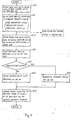
- Fig. 3 is a flow-chart representating a macro service executed by the microcomputer shown in Fig. 1;
- Fig. 4 is a block diagram representating a part of a microcomputer according to another embodiment of the present invention; and
- Fig. 5 is a flow chart representating a macro service executed by the microcomputer shown in Fig. 4.
- Referring to Fig. 1, a
microcomputer 100 according to an embodiment of the present invention includes a central processing unit (CPU) 101 and apulse producing unit 102 as a peripheral unit. This CPU 101 is constructed to perform a first interrupt processing service in which a processing responsive to an interrupt request is performed by executing a user's interrupt program after saving the contents a program counter (PC) 111 and a program status word register (PSW) 112 and a second interrupt processing service or a macro service in which a processing responsive to an interrupt request is performed without utilizing a user's program and without saving the contents of PC 111 andPSW 112. Thepulse producing unit 102 is constructed to control set and reset states of each output port in response immediately to set and reset timing signals. - More specifically, the CPU 101 includes an interrupt
request control unit 103, and execution unit 104 and adata memory 105. The interruptrequest control unit 103 receives set and resettiming signals pulse producing unit 102 and further receives auxiliary interrupt request signals AINT1 to AINTN from auxiliary interrupt request sources (not shown). A plurality of interrupt request detection flags (PSF, RSF, AF1 to AFN) 1031 to 1034 are provided for the respective interrupt request sources including thepulse producing unit 102. Each of theflags 1031 to 1034 is set when the corresponding interrupt request source generates an interrupt request. For example, the generation of the set and resettiming signal 132 sets the flags (PSF and RSF) 1031 and 1032, respectively. Thecontrol unit 103 also includes a plurality of interrupt mode designation flags (IMDF) for designating which service of the first and second interrupt processing services is to be executed with respect to the respective interrupt request sources. In Fig. 1, only IMDF 155 for thepulse producing unit 102 is shown. In this embodiment, the reset state of theflat 155 designates the first interrupt processing service, whereas the set state thereof designates the second interrupt processing service (macro service). Thecontrol unit 103 further includes an address pointer (SFRP) 123 and aregister 1035 required for the macro service for thepulse producing unit 102 which will be described later in detail. When either one of theflags 1031 to 1034 is set in response to the generation of the corresponding interrupt request, thecontrol unit 103 changes asignal line 106 to an active level to request an interrupt processing of the execution unit 104. Simultaneously, theunit 103 controls the logic level of aline 107 in response to the set or reset state of theflag 155 to designate the first or second interrupt processing service. In this embodiment, thesignal line 107 is controlled to a high level when theflag 155 is set. On the other hand, theline 107 takes a low level when theflag 155 is reset. Thecontrol unit 103 further transfers onto a signal line 1130 information representative of the interrupt request source generating an interrupt request. - The execution unit 104 includes a
program memory 110 storing a program made up by a user and containing a main routine and a plurality of interrupt routines, PC 111 designating an address of thememory 110 in which an instruction to be executed is stored,PSW 112 storing an execution condition of the unit 104, a general purpose register set 117, aninstruction register 115 temporarily storing an instruction which is currently being executed, anexecution control unit 116 generatingvarious control signals 1164 for executing the instruction stored in theregister 115, an arithmetic/logic unit (ALU) 114 performing an arithmetic and logic operation, and an interrupt request receiving unit 113 controlling theexecution control unit 116 in response to the interrupt information from the interrupt request control unit. The content of the PC 111 is updated every time the execution of the current instruction is terminated. Theexecution control unit 116 includes a microprogram memory 1162 and a microprogram counter (MPC) 1161 for addressing the memory 1161. The microprogram stored in the memory 1162 contains a microprogram for the macro services for a plurality of interrupt request sources including thepulse producing unit 102. The receiving unit 113 includes a register 1131 for storing vector address information IVAC for the first interrupt processing service and aregister 1132 for storing a macro service code MSC for the macro service. - The
data memory 105 stores data to be processed of operation result data and includes a macro servicecontrol data area 119 for storing information representative of a required macro service operation mode and a stack area 126 to which the contents of the PC 111 andPSW 112 are saved. - The
pulse producing unit 102 includes aset signal generator 127 generating aset signal 132 at set timings, areset signal generator 128 generates areset signal 133 at reset timings, an 8-bitparallel output port 131, an output portset control register 129 temporarily storing set data for designating a bit of theport 131 to be set and supplying it to theoutput port 131, and an output portreset control register 130 temporarily storing reset data for designating a bit of theport 131 to be reset and supplying it to theoutput port 131. The set andreset signals output port 131 and further to the interruptrequest control unit 103. Both of the set andreset signal generators reset signals parallel output port 131 consists of eightouput unit ports 134 to 141, each of which has a set ANDgate 142, a reset ANDgate 143, an R-S flip-flop 144, a driver 145 and an ouput terminal P. TheAND gage 142 sets the flip-flop 144 when both of theset signal 132 and the corresponding bit of the set data stored in theregister 129 take the high level, and theAND gage 143 resets the flip-flop 144 when both of thereset signal 133 and the corresponding bit of the reset data stored in theregister 130 take the high level. - Next, description will be made on the start of each of the first interrupt processing service and the macro service (second interrupt processing service).
- When the
pulse producing unit 102 or another interrupt request source generates an interrupt request, the interruptrequest control unit 103 changes thesignal line 106 to the active level to inform the execution unit 104 of the generation of the interrupt request. Simultaneously, theunit 103 produces the low level at theline 107 when the corresponding interrupt mode designation flag (IMDF 155, etc.) is reset or the high level at theline 107 when that flag is set, in order to designate the interrupt processing mode. The interrupt request receiving unit 113 in the execution unit 104 responds to the active level on theline 106 and producing an active level on asignal line 1133 to request theexecution control unit 116 to suspend the program execution. After execution of the current instruction, theexecution control unit 116 changes asignal line 1134 to the active level to inform the receiving unit 113 that the interrupt processing is allowed to be executed. In response to the active level of the line 113, the receiving unit 113 produces the active level on asignal line 1135 to reset the interruptrequest detection flag line 107. When theline 107 is at the low level, the unit 113 responds to the active level of theline 1134 and loads the vector address information IVAC stored in the register 1131 to theinstruction register 115 via aninternal bus 109. In response to theregister 115 being loaded with the information IVAC, theexecution control unit 116 saves the current contents of thePC 111 andPSW 112 to the stack area 126 of thedata memory 105 and transfers the leading address of a requested interrupt program routine to thePC 111. The interrupt program routine is thus started and executed. When the execution of the interrupt program is terminated, theexecution control unit 116 returns the saved contents to thePC 111 andPSW 112, respectively, so that the suspended main program is resumed. On the other hand, in case of the high level of theline 107, the unit 113 loads the macro service code MSC to theinstruction register 115. By this macro service code MSC, the macro service processing routine in the microprogram memory 1162 is started and executed by the execution unit 104 without saving the contents of thePC 111 andPSW 112 and without using any instructions in theprogram memory 110. During execution of the macro service, thePC 111 andPSW 112 are controlled to hold the contents thereof as they area. After the execution of the macro service, thePC 111 andPSW 112 are allowed to be changed to resume the suspended program. - Next, the macro service responsive to the set and reset
signals pulse producing unit 102 will be described in detail with reference also to Fig. 2 showing a timing chart of a pulse pattern which is used for controlling an electronic fuel injection apparatus of a vehicle engine. Since the interrupt request from thepulse producing unit 102 is processed by the macro service, theflag 155 in thecontrol unit 103 is set in an initial state, and theregister 1035 is stored with address SOPRA and ROPRA of the output port set and resetregisters area 119 of thedata memory 105 is stored with data MMR1 for designating the pulse producing macro service. In case where other macro services are also required, the designation data MMRM for those are stored in thearea 119. Moreover, both of theregisters program memory 110. - When the
set signal 132 is generated at a timing T₁₀, each of the set ANDgates 142 in theparallel output port 131 ANDs theset signal 132 and the corresponding bit of the initial value "00000001" of theregister 129, so that the flip-flop 144 of only theoutput port 134 is set. The output terminal PO is thereby changed to the high level and the remaining output terminals P1 to P7 are held at the low level. - The
set signal 132 is also supplied to the interruptrequest control unit 103, so that thecorresponding flag PSF 1031 is set. Theunit 103 changes theline 106 to the active level in response to the set state of theflag 1031; and further changes theline 107 to the high level in response to the set state of theflag 155. In addition, the information representing that the interrupt request source is thepulse producing unit 102 is outputted on to the line 1130. Moreover, thecontrol unit 103 loads to theaddress pointer SFRP 123 the address data SOPRA representative of the output port setcontrol register 129. After the execution of the current instruction by the execution unit 104, the interrupt request unit 113 transfers the macro service code MSC to theinstruction register 115 together with the information on the line 1130. As a result of theexecution control unit 116 decoding the macro service code MSC, the MPC 1161 is set with the leading address of the macro service processing loutine. The macro service thereby starts to be executed. - Turning to Fig. 3, there is shown a flow chart representative of the macro service according to the microprogram. At first, the
execution control unit 116 outputs an active level onto asignal line 1163 to hold the current contents of thePC 111 andPSW 112 as they are (Step 301). Based on the information representative of the interrupt request source which has been supplied along with the macro service code MSC, theunit 116 makes access to an address of the area 19 corresponding to that interrupt request source to read the macro service designation information therefrom. In the present description, since the designation information MMR1 is read out, the macro service for thepulse producing unit 102 is activated (Step 302). If other designation information (MMRM, for example) is read out, another macro service is activated as shown by a dotted line. In case where themicrocomputer 100 performs only the macro service for thepulse producing unit 102, thestep 302 is not required and thearea 119 can be omitted. - In the macro service for the
pulse producing unit 102, theexecution control unit 116 produces an active level on asignal line 124 and makes access to theregister unit 102 by make use of the content of theaddress pointer SFRP 123 in the interrupt request control unit 103 (Step 303). Since the content ofSFRP 123 is address data "SOPRA", the output port setcontrol register 129 is made access. Thereafter, theexecution control unit 116 commands theALU 114 to shift leftward the data of theregister 129 by one bit (Step 304). Thecontrol unit 116 detects whether or not a shift-out occurs in the shifted result data (Step 305), and writes the shifted result data into theregister 129 by make use of the address data in theSFRP 123 when the shift-out does not occur. As a result, the data in theregister 129 is changed to "0000 0010" from "0000 0001". Finally, theexecution control unit 116 makes theline 1163 be at an inactive level to allow thePC 111 andPSW 112 to change the contents thereof (Step 307), so that the macro service is terminated. The suspended program execution is thereby resumed, and the execution unit 104 starts to execute the instruction read from the address of theprogram memory 110 designated byPC 111. - The operation responsive to each of the set signals 132 occuring at timings T₁₁, T₁₂, T₁₃, T₁₄, T₁₅, T₁₆, T₁₈ and T₁₉ is similar to that at the timing T₁₀, so that the output terminal P to be changed to the high level is changed sequentially and the data of the
register 129 is shifted leftward one bit by one via. On the other hand, when theset signal 132 is generated at a timing T₁₇, each of the set ANDgates 142 ANDs theset signal 132 and the corresponding bit of the set data "1000 0000", so that the flip-flop 144 of theoutput port 141 is set to produce a pulse at the output terminal P7. In the macro service responsive to the set signal at this time, the shift-out occurs at thestep 305. Therefore, theexecution control unit 116 changes asignal line 108 to an active level to setPSF 1031 orPRF 1032 in the interruptrequest control unit 103 and resetIMDF 155, followed by executing thestep 307 to terminate the macro service. SincePSF 1031 orPRF 1032 is set andIMDF 155 is reset, thecontrol unit 103 changes theline 106 to the active level and theline 107 to the low level. As a result, the interrupt vector address information IVAC is loaded to theinstruction register 115. In response thereto, theexecution control unit 116 saves the contents ofPC 111 andPSW 112 to the stack area 126 of thedata memory 105 and transfers the leading address of an interrupt program routine to thePC 111 to execute the interrupt program routine. In this routine, the register designated by the address data stored in theSFRP 123, i.e. the output port setcontrol register 129, is written with the initial value "0000 0001" and theIMDF 155 is set. After execution of the interrupt program routine, the saved contents are returned to thePC 111 andPSW 112, respectively, to resume the suspended program. - When the
reset signal 133 is generated at timing T₂₀ by thereset generator 128, each of the reset ANDgates 143 ANDs thereset signal 133 and the corresponding bit of the reset data "0000 0001", so that the flip-flop 144 of theport 134 is reset. The output terminal PO is thereby changed to the low level to stop the production of a pulse. - The
reset signal 133 sets thePRF 1032. Accordingly, the interruptrequest control unit 103 changes theline 106 to the active level and theline 107 to the high level and stores into theSFRP 123 the address data "ROPRA" representative of the output port resetcontrol register 130. The macro service is thereby activated to shift leftward the data of theregister 130 by one bit. The data of theregister 130 is thus changed to "0000 0010". The operation responsive to each of the reset signals 133 occurring at timings T₂₁, T₂₂, T₂₃, T₂₄, T₂₅ and T₂₆ is similar to that at the timing T₂₀. In response to the reset signal 133 at a timing T₂₇, each of the reset ANDgates 143 ANDs thereset signal 133 and the corresponding bit of the reset data "1000 0000", so that the flip-flop 144 of theport 141 is reset to change the output terminal P7 to the low level. In the macro service responsive to the reset signal 133 at this time, the shift-out occurs in the one-bit-shifted result data. Therefore, the first interrupt processing service is activated to write the initial value "0000 0001" into the register BO and set theflag 155. Moreover, the timing correction of thegenerators - Thus, the pulse pattern shown in Fig. 2 is derived from the
output port 131 of themicrocomputer 100. The leading and falling edges of each pulse are substantially coincident with the set and resetsignals registers - Turning to Fig. 2, a
pulse producing unit 102′ according to another embodiment of the present invention further including a set initial data register 151 storing set initial data "0000 0001" and a reset initial data register 152 storing reset initial data "0000 0001". The set initial data from the register 151 is written into theregister 129 by apreset signal 153 and the reset initial data from theregister 152 is written into theregister 130 by apreset signal 154. Thesepresent signals execution control unit 116 when a shift-out occurs by shifting leftward the set and reset data, respectively. Therefore, the flow chart of the macro service according to this embodiment is shown in Fig. 5. In place of thestep 308 shown in Fig. 3, ageneration step 400 of thepreset signal registers - The present invention is not limited to the above embodiments, but may be modified and changed without departing from the scope and spirit of the invention.
Claims (7)
a central processor including a program memory storing a program to be executed, a program counter designating an address of said program memory in which an instruction to be executed is stored, and an execution unit executing the instruction from said program memory;
and
a pulse producing unit including a plurality of output terminals, a register temporarily storing data for designating at least one of said output terminals at which a pulse is to be produced, means for generating a timing signal, and means responsive to said timing signal for producing a pulse at said at least one of said output terminal designated by said data;
said central processor further including means responsive to said timing signal for suspending said program being executed and means for executing a macro service without saving a content of said program counter and with holding the content of said program counter, said macro service executing means including means for accessing said register to read the data therefrom, means for changing the read-out data, means for writing the changed data into said register, and means for allowing said program counter to change the content thereof after said changed data is written into said register.
Applications Claiming Priority (2)
| Application Number | Priority Date | Filing Date | Title |
|---|---|---|---|
| JP66454/88 | 1988-03-18 | ||
| JP6645488 | 1988-03-18 |
Publications (3)
| Publication Number | Publication Date |
|---|---|
| EP0333213A2 true EP0333213A2 (en) | 1989-09-20 |
| EP0333213A3 EP0333213A3 (en) | 1992-05-20 |
| EP0333213B1 EP0333213B1 (en) | 1996-07-31 |
Family
ID=13316235
Family Applications (1)
| Application Number | Title | Priority Date | Filing Date |
|---|---|---|---|
| EP19890104804 Expired - Lifetime EP0333213B1 (en) | 1988-03-18 | 1989-03-17 | Microcomputer producing pulses at outout ports in sequence in response to request signal |
Country Status (2)
| Country | Link |
|---|---|
| EP (1) | EP0333213B1 (en) |
| DE (1) | DE68926889T2 (en) |
Citations (2)
| Publication number | Priority date | Publication date | Assignee | Title |
|---|---|---|---|---|
| JPS61134265A (en) * | 1984-12-03 | 1986-06-21 | Nec Corp | Dot pattern output apparatus |
| JPS63118949A (en) * | 1986-11-07 | 1988-05-23 | Nec Corp | Information processor |
-
1989
- 1989-03-17 DE DE1989626889 patent/DE68926889T2/en not_active Expired - Fee Related
- 1989-03-17 EP EP19890104804 patent/EP0333213B1/en not_active Expired - Lifetime
Patent Citations (2)
| Publication number | Priority date | Publication date | Assignee | Title |
|---|---|---|---|---|
| JPS61134265A (en) * | 1984-12-03 | 1986-06-21 | Nec Corp | Dot pattern output apparatus |
| JPS63118949A (en) * | 1986-11-07 | 1988-05-23 | Nec Corp | Information processor |
Non-Patent Citations (4)
| Title |
|---|
| IEEE MICRO vol. 6, no. 6, December 1986, NEW YORK US pages 29 - 48; K. L. KLOKER: 'The Motorola DSP56000 Digital Signal Processor' * |
| PATENT ABSTRACTS OF JAPAN vol. 10, no. 326 (M-532)6 November 1986 & JP-A-61 134 265 ( NEC CORP ) 21 June 1986 * |
| PATENT ABSTRACTS OF JAPAN vol. 12, no. 368 (P-766)(3215) 4 October 1988 & JP-A-63 118 949 ( NEC CORP ) 23 May 1988 * |
| WESCON/87 CONFERENCE RECORD vol. 31, no. 1/3, 1987, LOS ANGELES, CALIFORNIA, US pages 1 - 7; D. H. COBBS: 'The V35: A Microcomputer that services interrupts without software' * |
Also Published As
| Publication number | Publication date |
|---|---|
| EP0333213B1 (en) | 1996-07-31 |
| DE68926889T2 (en) | 1997-03-13 |
| DE68926889D1 (en) | 1996-09-05 |
| EP0333213A3 (en) | 1992-05-20 |
Similar Documents
| Publication | Publication Date | Title |
|---|---|---|
| EP0464615B1 (en) | Microcomputer equipped with DMA controller | |
| US4987537A (en) | Computer capable of accessing a memory by supplying an address having a length shorter than that of a required address for the memory | |
| US4961161A (en) | Arithmetic processor performing mask and trap operations for exceptions | |
| EP0313097A2 (en) | Microcomputer system including master processor and slave processor | |
| EP0369470B1 (en) | Data processing apparatus for producing in sequence pulses having variable width at output ports | |
| EP0333213A2 (en) | Microcomputer producing pulses at outout ports in sequence in response to request signal | |
| JPS61123959A (en) | Electronics equipment having attachable/detachable memory module | |
| EP0333231B1 (en) | Microcomputer system capable of accessing to memory at high speed | |
| JP2551139B2 (en) | Information processing device | |
| EP0284100A2 (en) | Information processor having instruction prefetch function | |
| JPS6230455B2 (en) | ||
| JP2903526B2 (en) | Pulse generator | |
| JP2674873B2 (en) | Step execution operation method of program development support device | |
| JP2575025B2 (en) | In-circuit emulator | |
| JPH02133833A (en) | Controller for in-circuit emulator | |
| JPS6052449B2 (en) | Interrupt processing method | |
| JPH0652013A (en) | Tracing circuit | |
| JPH02259932A (en) | Interruption processing system | |
| JPS60193046A (en) | Detecting system for instruction exception | |
| JPH0795288B2 (en) | Microcomputer | |
| JPS62169231A (en) | Processor | |
| JPS63241636A (en) | Data processor | |
| JPS61160146A (en) | Control system of address stack pointer device | |
| JPS6349943A (en) | Arithmetic processing unit | |
| JPH02136543A (en) | Fuel injection controller |
Legal Events
| Date | Code | Title | Description |
|---|---|---|---|
| PUAI | Public reference made under article 153(3) epc to a published international application that has entered the european phase |
Free format text: ORIGINAL CODE: 0009012 |
|
| 17P | Request for examination filed |
Effective date: 19890317 |
|
| AK | Designated contracting states |
Kind code of ref document: A2 Designated state(s): DE FR GB |
|
| PUAL | Search report despatched |
Free format text: ORIGINAL CODE: 0009013 |
|
| AK | Designated contracting states |
Kind code of ref document: A3 Designated state(s): DE FR GB |
|
| 17Q | First examination report despatched |
Effective date: 19940310 |
|
| GRAH | Despatch of communication of intention to grant a patent |
Free format text: ORIGINAL CODE: EPIDOS IGRA |
|
| GRAA | (expected) grant |
Free format text: ORIGINAL CODE: 0009210 |
|
| AK | Designated contracting states |
Kind code of ref document: B1 Designated state(s): DE FR GB |
|
| GRAH | Despatch of communication of intention to grant a patent |
Free format text: ORIGINAL CODE: EPIDOS IGRA |
|
| REF | Corresponds to: |
Ref document number: 68926889 Country of ref document: DE Date of ref document: 19960905 |
|
| ET | Fr: translation filed |
Free format text: CORRECTIONS |
|
| PLBE | No opposition filed within time limit |
Free format text: ORIGINAL CODE: 0009261 |
|
| STAA | Information on the status of an ep patent application or granted ep patent |
Free format text: STATUS: NO OPPOSITION FILED WITHIN TIME LIMIT |
|
| 26N | No opposition filed | ||
| REG | Reference to a national code |
Ref country code: GB Ref legal event code: IF02 |
|
| PGFP | Annual fee paid to national office [announced via postgrant information from national office to epo] |
Ref country code: FR Payment date: 20020312 Year of fee payment: 14 |
|
| PGFP | Annual fee paid to national office [announced via postgrant information from national office to epo] |
Ref country code: GB Payment date: 20020320 Year of fee payment: 14 |
|
| PGFP | Annual fee paid to national office [announced via postgrant information from national office to epo] |
Ref country code: DE Payment date: 20020327 Year of fee payment: 14 |
|
| PG25 | Lapsed in a contracting state [announced via postgrant information from national office to epo] |
Ref country code: GB Free format text: LAPSE BECAUSE OF NON-PAYMENT OF DUE FEES Effective date: 20030317 |
|
| PG25 | Lapsed in a contracting state [announced via postgrant information from national office to epo] |
Ref country code: DE Free format text: LAPSE BECAUSE OF NON-PAYMENT OF DUE FEES Effective date: 20031001 |
|
| GBPC | Gb: european patent ceased through non-payment of renewal fee |
Effective date: 20030317 |
|
| PG25 | Lapsed in a contracting state [announced via postgrant information from national office to epo] |
Ref country code: FR Free format text: LAPSE BECAUSE OF NON-PAYMENT OF DUE FEES Effective date: 20031127 |
|
| REG | Reference to a national code |
Ref country code: FR Ref legal event code: ST |