EP0333035B1 - Flexible grinding tool - Google Patents
Flexible grinding tool Download PDFInfo
- Publication number
- EP0333035B1 EP0333035B1 EP89104191A EP89104191A EP0333035B1 EP 0333035 B1 EP0333035 B1 EP 0333035B1 EP 89104191 A EP89104191 A EP 89104191A EP 89104191 A EP89104191 A EP 89104191A EP 0333035 B1 EP0333035 B1 EP 0333035B1
- Authority
- EP
- European Patent Office
- Prior art keywords
- finish
- grinding tool
- tool according
- constituent
- back side
- Prior art date
- Legal status (The legal status is an assumption and is not a legal conclusion. Google has not performed a legal analysis and makes no representation as to the accuracy of the status listed.)
- Expired - Lifetime
Links
- 239000002245 particle Substances 0.000 claims abstract description 20
- XEEYBQQBJWHFJM-UHFFFAOYSA-N Iron Chemical compound [Fe] XEEYBQQBJWHFJM-UHFFFAOYSA-N 0.000 claims abstract description 12
- 229910052742 iron Inorganic materials 0.000 claims abstract description 6
- 229910052500 inorganic mineral Inorganic materials 0.000 claims abstract description 4
- 239000011707 mineral Substances 0.000 claims abstract description 4
- 238000004519 manufacturing process Methods 0.000 claims description 3
- 239000000470 constituent Substances 0.000 claims 8
- 239000012141 concentrate Substances 0.000 claims 1
- 239000012530 fluid Substances 0.000 claims 1
- 230000005484 gravity Effects 0.000 claims 1
- 238000000034 method Methods 0.000 claims 1
- 238000009958 sewing Methods 0.000 description 13
- 239000000835 fiber Substances 0.000 description 11
- 239000004615 ingredient Substances 0.000 description 10
- 239000011230 binding agent Substances 0.000 description 7
- 230000000694 effects Effects 0.000 description 6
- 239000004753 textile Substances 0.000 description 6
- OKTJSMMVPCPJKN-UHFFFAOYSA-N Carbon Chemical compound [C] OKTJSMMVPCPJKN-UHFFFAOYSA-N 0.000 description 5
- 239000010439 graphite Substances 0.000 description 5
- 229910002804 graphite Inorganic materials 0.000 description 5
- 239000010445 mica Substances 0.000 description 5
- 229910052618 mica group Inorganic materials 0.000 description 5
- 238000005299 abrasion Methods 0.000 description 4
- 239000004744 fabric Substances 0.000 description 4
- 239000006185 dispersion Substances 0.000 description 3
- 239000000126 substance Substances 0.000 description 3
- 101000950718 Homo sapiens Inositol oxygenase Proteins 0.000 description 2
- 102100037804 Inositol oxygenase Human genes 0.000 description 2
- 230000000052 comparative effect Effects 0.000 description 2
- 230000007423 decrease Effects 0.000 description 2
- 230000002349 favourable effect Effects 0.000 description 2
- 239000002657 fibrous material Substances 0.000 description 2
- LIKBJVNGSGBSGK-UHFFFAOYSA-N iron(3+);oxygen(2-) Chemical compound [O-2].[O-2].[O-2].[Fe+3].[Fe+3] LIKBJVNGSGBSGK-UHFFFAOYSA-N 0.000 description 2
- 239000004816 latex Substances 0.000 description 2
- 229920000126 latex Polymers 0.000 description 2
- 239000000463 material Substances 0.000 description 2
- 239000000203 mixture Substances 0.000 description 2
- 239000005011 phenolic resin Substances 0.000 description 2
- KXGFMDJXCMQABM-UHFFFAOYSA-N 2-methoxy-6-methylphenol Chemical compound [CH]OC1=CC=CC([CH])=C1O KXGFMDJXCMQABM-UHFFFAOYSA-N 0.000 description 1
- 229920002126 Acrylic acid copolymer Polymers 0.000 description 1
- 229920002522 Wood fibre Polymers 0.000 description 1
- 230000002411 adverse Effects 0.000 description 1
- 238000005452 bending Methods 0.000 description 1
- 230000015572 biosynthetic process Effects 0.000 description 1
- 239000003795 chemical substances by application Substances 0.000 description 1
- 239000011093 chipboard Substances 0.000 description 1
- 239000011248 coating agent Substances 0.000 description 1
- 238000000576 coating method Methods 0.000 description 1
- 150000001875 compounds Chemical class 0.000 description 1
- 238000010276 construction Methods 0.000 description 1
- 238000010586 diagram Methods 0.000 description 1
- 238000001035 drying Methods 0.000 description 1
- 239000000428 dust Substances 0.000 description 1
- 239000000945 filler Substances 0.000 description 1
- 230000001771 impaired effect Effects 0.000 description 1
- 238000009434 installation Methods 0.000 description 1
- 239000007788 liquid Substances 0.000 description 1
- 239000000314 lubricant Substances 0.000 description 1
- 230000035515 penetration Effects 0.000 description 1
- ISWSIDIOOBJBQZ-UHFFFAOYSA-N phenol group Chemical group C1(=CC=CC=C1)O ISWSIDIOOBJBQZ-UHFFFAOYSA-N 0.000 description 1
- 229920001568 phenolic resin Polymers 0.000 description 1
- 239000004033 plastic Substances 0.000 description 1
- 230000002787 reinforcement Effects 0.000 description 1
- 230000003014 reinforcing effect Effects 0.000 description 1
- 238000004062 sedimentation Methods 0.000 description 1
- 239000007779 soft material Substances 0.000 description 1
- 239000007787 solid Substances 0.000 description 1
- 238000005728 strengthening Methods 0.000 description 1
- 239000000758 substrate Substances 0.000 description 1
- 229920003002 synthetic resin Polymers 0.000 description 1
- 239000000057 synthetic resin Substances 0.000 description 1
- 239000002025 wood fiber Substances 0.000 description 1
Images

Classifications
-
- B—PERFORMING OPERATIONS; TRANSPORTING
- B24—GRINDING; POLISHING
- B24D—TOOLS FOR GRINDING, BUFFING OR SHARPENING
- B24D11/00—Constructional features of flexible abrasive materials; Special features in the manufacture of such materials
- B24D11/02—Backings, e.g. foils, webs, mesh fabrics
-
- Y—GENERAL TAGGING OF NEW TECHNOLOGICAL DEVELOPMENTS; GENERAL TAGGING OF CROSS-SECTIONAL TECHNOLOGIES SPANNING OVER SEVERAL SECTIONS OF THE IPC; TECHNICAL SUBJECTS COVERED BY FORMER USPC CROSS-REFERENCE ART COLLECTIONS [XRACs] AND DIGESTS
- Y10—TECHNICAL SUBJECTS COVERED BY FORMER USPC
- Y10T—TECHNICAL SUBJECTS COVERED BY FORMER US CLASSIFICATION
- Y10T442/00—Fabric [woven, knitted, or nonwoven textile or cloth, etc.]
- Y10T442/20—Coated or impregnated woven, knit, or nonwoven fabric which is not [a] associated with another preformed layer or fiber layer or, [b] with respect to woven and knit, characterized, respectively, by a particular or differential weave or knit, wherein the coating or impregnation is neither a foamed material nor a free metal or alloy layer
- Y10T442/2041—Two or more non-extruded coatings or impregnations
- Y10T442/2049—Each major face of the fabric has at least one coating or impregnation
- Y10T442/2057—At least two coatings or impregnations of different chemical composition
- Y10T442/2074—At least one coating or impregnation contains particulate material
Definitions
- the solution according to the invention consists in that, in the case of a flexible grinding tool of the type mentioned at the outset, the rear side finish contains a platelet-shaped, mineral ingredient in a proportion of the hardened rear side finish of at least 2% by weight.
Abstract
Description
Die Erfindung betrifft ein flexibles Schleifwerkzeug, insbesondere Schleifband, mit einer flexiblen Unterlage, die eine Rückseitenappretur trägt.The invention relates to a flexible grinding tool, in particular grinding belt, with a flexible base which carries a rear side finish.
Bei flexiblen Schleifwerkzeugen ist häufig eine hohe Festigkeit der Unterlage gegenüber Walk- und Biegebeanspruchungen erwünscht. Es ist bekannt, daß diese Eigenschaft bei auf Fasermaterial, beispielsweise Gewebe, beruhenden Unterlagen durch Verwendung einer im flüssigen Zustand aufgetragenen, erhärtenden Rückseitenappretur verbessert werden kann, die teils in die Faser- oder Fadenzwischenräume eindringt und teils als Schicht auf der Rückseite der Unterlage verbleibt. Im Hinblick auf ihre verfestigende Funktion sowie ihre Widerstandsfähigkeitgegenüberden mechanischen Beanspruchungen einer Schleifmaschine soll sie hohe Eigenfestigkeit aufweisen. Es werden deshalb in der Regel solche Appreturen verwendet, die im ausgehärteten Zustand vergleichsweise hart sind. Im Unterschied dazu verwendet man verhältnismäßig weich bleibende Stoffe fürdie sogenannte Kernappretur, die vordem Aufbringen der Rückseiten- und Kornseitenappretur in das Fasermaterial eingebracht wird, um das Durchschlagen der Seitenappreturen zu vermeiden und die Fasern vor ggf. aggressiven und versprödenden Einflüssen der Seitenappreturen zu schützen.In the case of flexible grinding tools, it is often desirable for the backing to have a high strength against flexing and bending stresses. It is known that this property can be improved in the case of underlays based on fiber material, for example fabric, by using a hardening backside finish applied in the liquid state, which partially penetrates into the interstices of fibers or threads and partly remains as a layer on the back of the underlay. In view of its strengthening function and its resistance to the mechanical stresses of a grinding machine, it should have high inherent strength. For this reason, finishes are generally used that are comparatively hard when hardened. In contrast, relatively soft materials are used for the so-called core finish, which is introduced into the fiber material prior to the application of the rear and grain side finish in order to prevent the side finishes from breaking through and to protect the fibers from possibly aggressive and embrittling influences of the side finishes.
Weiterhin strebt man mit dem Auftrag der Rückseitenappretur das Glätten der Rückseite der Unterlage an, die entsprechend der textilen Struktur im allgemeinen uneben oder rauh ist. Jedoch ist es mit üblichen Appreturen nicht möglich, die Unebenheit der Rückfläche gänzlich zu beseitigen, da sich nach dem Aushärten der Appretur die Oberflächenstruktur der Unterlage mit mehr oder weniger großen Höhenunterschieden in der Oberfläche der von der Appretur gebildeten Schicht abzeichnet. Es gibt Arten von textilem Flächenmaterial, die eine besonders unebene Rückseite aufweisen. Dazu gehören Nähgewirke mit rückseitig aufliegenden Fasersträngen, die mittels eines Nähwirkfadens verbunden sind. Die Faserstränge treten als Erhöhungen mit dazwischenliegenden Vertiefungen in Erscheinung. Eine noch größere Höhe erreichen die über die Faserstränge hinweggehenden Nähfäden. So kann bei einem marktgängigen Produkt der Abstand zwischen der Unterseite des Kettgarns und dem höchsten Punkt des Nähwirkfadens in der Größenordnung von 0,3 bis 0,5 mm liegen bei einem Mittenabstand der Faserstränge von 1,8 mm. In der Schleifzone stützt sich das Schleifband über seine rückseitig höchsten Stellen an der Stützstruktur der Schleifmaschine ab. Wenn die Stützstruktur von stationären Stützelementen gebildet ist, über die das Schleifband hinweggleitet, kann sich die unebene Gestalt der Schleifbandrückseite stark abrasiv auswirken, insbesondere wenn die Stützelemente mit graphithaltigen Gleitbelägen versehen sind, die über Druckbalken gespannt die Reibung zwischen Schleifbandrückseite und Druckbalkenoberfläche vermindern sollen. Man hat versucht, die rückseitige Rauheit der Unterlage durch eine Vliesauflage zu vermindern (WO 86/02306) ; jedoch ist dies sehr aufwendig.Furthermore, the application of the rear side finish strives to smooth the back of the base, which is generally uneven or rough according to the textile structure. However, it is not possible with conventional finishes to completely remove the unevenness of the back surface, since after the finish has hardened, the surface structure of the base becomes apparent with more or less large differences in height in the surface of the layer formed by the finish. There are types of textile surface material that have a particularly uneven back. This includes knitted fabrics with fiber strands on the back, which are connected by means of a sewing thread. The fiber strands appear as elevations with intervening depressions. The sewing threads crossing the fiber strands reach an even greater height. For a marketable product, the distance between the underside of the warp yarn and the highest point of the sewing thread can be in the order of 0.3 to 0.5 mm with a center distance of the fiber strands of 1.8 mm. In the sanding zone, the sanding belt is supported on the rear structure of the sanding machine's support structure. If the support structure is formed by stationary support elements over which the sanding belt slides, the uneven shape of the back of the sanding belt can have a highly abrasive effect, especially if the support elements are provided with graphite-containing sliding coverings that are stretched over pressure bars to reduce the friction between the back of the sanding belt and the pressure bar surface. Attempts have been made to reduce the roughness of the backing of the base by means of a non-woven covering (WO 86/02306); however, this is very expensive.
Der Erfindung liegt die Aufgabe zugrunde, die verschleißende Wirkung der Rückseite des Schleifwerkzeugs auf die Stützstruktur der Schleifmaschine zu verringern und die mechanischen Eigenschaften des Schleifwerkzeugs zu verbessern.The invention has for its object to reduce the wear effect of the back of the grinding tool on the support structure of the grinding machine and to improve the mechanical properties of the grinding tool.
Die erfindungsgemäße Lösung besteht darin, daß bei einem flexiblen Schleifwerkzeug der eingangs genannten Art die Rückseitenappretur einen plättchenförmigen, mineralischen Inhaltsstoff in einem Anteil an der ausgehärteten Rückseitenappretur von mindestens 2 Gew.% enthält.The solution according to the invention consists in that, in the case of a flexible grinding tool of the type mentioned at the outset, the rear side finish contains a platelet-shaped, mineral ingredient in a proportion of the hardened rear side finish of at least 2% by weight.
Der Inhaltsstoff versteift die ihn einschließende Schicht und erhöht dadurch die Widerstandsfähigkeit des Werkzeugs. Während es bisher erforderlich war, diese Widerstandsfähigkeit durch geeignete Auswahl der Härte, der Schichtdicke und der Eindringtiefe der Rückseitenappretur zu beeinflussen, können diese Parameter nun freier gewählt werden.The ingredient stiffens the layer enclosing it, thereby increasing the resistance of the tool. While it was previously necessary to influence this resistance by suitable selection of the hardness, the layer thickness and the depth of penetration of the rear side finish, these parameters can now be chosen more freely.
Das gilt insbesondere für diejenigen Parameter, die die erläuterte, verschleißende Eigenschaft des Werkzeugs betreffen. Insofern beruht die Erfindung auf der Feststellung, daß zum einen die bislang üblichen, harten Einstellungen der Rückseitenappretur die verschleißenden Eigenschaften des Werkzeugs ungünstig beeinflussen, und daß zum anderen eine weiche Einstellung der Rückseitenappretur den durch die Werkzeugrückseite verursachten Verschleiß vermindert.This applies in particular to those parameters which relate to the wear property of the tool explained. In this respect, the invention is based on the finding that, on the one hand, the hitherto customary hard settings of the rear side finish adversely affect the wear properties of the tool, and on the other hand that a soft setting of the rear side finish reduces the wear caused by the back of the tool.
Unter der Weichheit der ausgehärteten Rückseitenappretur ist in erster Linie die Shore-Härte zu verstehen, die nicht höher als 90 Shore A, vorzugsweise nicht höher als 85 Shore A und weiter vorzugsweise nicht höher als 80 Shore A sein soll. Härtebereiche zwischen 60 und 80 Shore A haben sich bewährt. Es ist anzunehmen, daß für die erfindungsgemäße Wirkung nicht nur die Härte als solche, sondern auch die dadurch bedingte, höhere Verschleißbarkeit der Rückseitenappretur verantwortlich ist. Unter Weichheit im Sinne der Erfindung soll daher vorzugsweise auch eine verhältnismäßig hohe Verschleißbarkeit verstanden werden. Dadurch werden rückseitige Erhebungen, die andernfalls abrasiv wirken könnten, rascher abgetragen, und es bilden sich an diesen Stellen ebene oder sanft gerundete, tragende Flächen. Das gilt insbesondere für die Stellen, die infolge darunter liegender Nähwirkfäden angehoben sind. Es schadet nicht, wenn nach dem Verschleiß der Rückseitenappretur an diesen Stellen die Nähwirkfäden frei liegen, zumal sie nach kurzer Betriebsdauer von Gleitmittel, beispielsweise Graphitstaub, der von den Stützelementen abgerieben wird, durchsetzt werden. Eine Vielzahl gleitmitteldurchsetzter Faserbündel der Nähwirkfäden kann in ihrer Gesamtheit eine reibungsarme Gleit- und Kontaktfläche des Schleifbandes gegenüber dem Stützelement bilden.The softness of the hardened backside finish is to be understood primarily as the Shore hardness, which should not be higher than 90 Shore A, preferably not higher than 85 Shore A and further preferably not higher than 80 Shore A. Hardness ranges between 60 and 80 Shore A have proven their worth. It can be assumed that not only the hardness as such, but also the resulting higher wear resistance of the rear side finish is responsible for the effect according to the invention. Softness in the sense of the invention should therefore preferably also be understood to mean a relatively high wearability. As a result, rear elevations, which could otherwise have an abrasive effect, are removed more quickly, and flat or gently rounded, supporting surfaces are formed at these points. This applies in particular to the areas that are raised as a result of sewing threads underneath. It does no harm if after the wear of the back side finish the sewing threads are exposed at these points, especially since after a short period of operation they are penetrated by lubricant, for example graphite dust, which is rubbed off by the support elements. A variety of lubricant-penetrated fiber bundles Sewing threads in their entirety can form a low-friction sliding and contact surface of the grinding belt with respect to the support element.
Zwar ist es bekannt (US-A 3 166 388), in einer Unterlage aus Holzfaservlies polymere Verstärkungspartikel einzusetzen ; jedoch hat dieser Vorschlag keine Beziehung zu den verschleißenden Eigenschaften einer Schleifband-Rückseite und einer Rückseitenappretur.It is known (US Pat. No. 3,166,388) to use polymeric reinforcement particles in a base made of wood fiber fleece; however, this proposal has no relation to the abrasive properties of a backsheet and backsize finish.
Die Weichheit bzw. Verschleißbarkeit der Rückseitenappretur wird zweckmäßigerweise so gewählt, daß die höchsten Rückseitenstellen nach etwa einem Zehntel der vorgesehenen Lebensdauer des Schleifbands weitgehend zur Bildung gleitgünstiger Flächenanteile abgetragen sind. Dies entspricht bei marktgängigen Produkten einer Zeitdauer von etwa einer halben Stunde.The softness or wearability of the rear side finish is expediently chosen so that the highest rear side locations are largely removed after approximately one tenth of the intended service life of the abrasive belt in order to form areas with favorable sliding properties. For marketable products, this corresponds to a period of around half an hour.
Die armierende Wirkung der plättchenförmigen Partikeln ist um so besser, je mehr sie parallel zur Werkzeugerstreckung angeordnet sind. Eine vorteilhafte Ausführungsform der Erfindung zeichnet sich daher dadurch aus, daß in der Ausrichtung der Partikeln die parallel zur Werkzeugerstreckung vedaufende Richtungskomponente überwiegt. Dies kann auch günstig sein im Hinblick auf die Gleit- und Verschleißeigenschaften des Werkzeugs. Auch eine vielfache gegenseitige Überlappung benachbarter Partikeln trägt zur Aussteifung bei. Das gilt insbesondere dann, wenn die Teilchen dicht der rückseitigen Oberfläche der Unterlage angelagert sind und auch geringen gegenseitigen Abstand voneinander haben. Ein solcher Zustand kann erfindungsgemäß dadurch erreicht werden, daß man dafür sorgt, daß die Appreturwenigstens in einer Herstellungsphase, in welcher das Band horizontal oder schwach geneigt verläuft, so niedrigviskos ist, daß sich die Teilchen in der Nähe der rückseitigen Oberfläche der Unterlage anreichern. In einem vorteilhaften Extremfall bilden die Teilchen eine auf der Unterlagenrückseite sedimentierte Schicht, während derjenige Teil der rückseitigen Appretur, der ihrer freien Oberfläche näher liegt, weitgehend frei oder deutlich ärmer an Teilchen ist. Die Vorteile dieses Aufbaus liegen zum einen in der verbesserten Aussteifungswirkung derTeilchen und zum anderen darin, daß sie in der äußersten Appreturzone, die für die Gleiteigenschaften maßgebend ist, fehlen und daher ohne Rücksicht auf ihre Gleiteigenschaften gewählt werden können. Für die Absenkung der Teilchen auf die rückseitige Oberfläche der Unterlage ist ein hohes spezifisches Gewicht derselben vorteilhaft, beispielsweise in der Größenordnung von 5 g/cm3.The reinforcing effect of the platelet-shaped particles is better the more they are arranged parallel to the tool extension. An advantageous embodiment of the invention is therefore characterized in that the directional component, which runs parallel to the tool extension, predominates in the alignment of the particles. This can also be favorable with regard to the sliding and wear properties of the tool. A multiple mutual overlap of neighboring particles also contributes to the stiffening. This is particularly true when the particles are tightly attached to the back surface of the base and are also close to one another. Such a condition can be achieved according to the invention by ensuring that the finish is so low-viscosity, at least in a manufacturing phase in which the tape is horizontal or slightly inclined, that the particles accumulate near the back surface of the base. In an advantageous extreme case, the particles form a layer sedimented on the back of the underlay, while that part of the finish on the back that is closer to their free surface is largely free or significantly poorer in particles. The advantages of this construction lie on the one hand in the improved stiffening effect of the particles and on the other hand in the fact that they are absent in the outermost finishing zone, which is decisive for the sliding properties, and can therefore be chosen without regard to their sliding properties. A high specific weight of the substrate is advantageous for lowering the particles onto the back surface of the base, for example in the order of 5 g / cm 3.
Wenn in den Ansprüchen und der Beschreibung von einem Inhaltsstoff die Rede ist, so soll dies keine Beschränkung auf nur eine Sorte von Partikeln bedeuten. Vielmehr können verschiedene Stoffe gemeinsam den Inhaltsstoff bilden.When an ingredient is mentioned in the claims and the description, this should not mean a restriction to only one type of particle. Rather, different substances can together form the ingredient.
Die auf der Rückseite der Unterlage ausgebrachte Menge des Inhaltsstoffs soll mindestens 3 g/m2, vorzugsweise mehr als 8 g/m2 betragen. Dabei soll der Inhaltsstoffanteil in der ausgehärteten Rückseitenappretur, vorzugsweise mehr als 8 Gew.-%, beispielsweise um 15 Gew.-% betragen.The amount of the ingredient applied on the back of the base should be at least 3 g / m 2 , preferably more than 8 g / m 2 . The proportion of ingredients in the cured backside finish should preferably be more than 8% by weight, for example around 15% by weight.
Vorteilhafterweise enthält der Inhaltsstoff schichtkristalline Partikel, die ebenfalls eine Vorzugsausrichtung in Gleitrichtung haben sollten.The ingredient advantageously contains layer-crystalline particles, which should also have a preferred orientation in the sliding direction.
Hervorragend hat sich Eisenglimmer bewährt. Desgleichen können andere Glimmerarten verwendetwerden, und zwar zweckmäßigerweise im Zusammenhang mit einem vergleichsweise weichen Bindemittel.Iron mica has proven to be excellent. Likewise, other types of mica can be used, conveniently in conjunction with a comparatively soft binder.
Während erfindungsgemäß die Gleiteigenschaften verbessert werden, wird die Energieübertragung von der Antriebsscheibe oder -rolle auf das Schleifband nicht beeinträchtigt.While the sliding properties are improved according to the invention, the energy transfer from the drive pulley or roller to the grinding belt is not impaired.
Verwendbar sind alle zur Schichtbildung geeigneten Bindemittel, insbesondere Kunstharze und Kunststoff-Dispersionen bzw. Mischungen solcher Stoffe. Bewährt haben sich Rückseitenappreturen aus Phenolharz-Latexmischungen. Die vergleichsweise weiche, erfindungsgemäße Rückseitenappretur enthält vorzugsweise als Bindemittelkomponente in noch nicht ausgehärtetem Zustand Phenolharz und eine Acrylsäureester-Copolymerisat-Dispersion in einem Gewichtsverhältnis von 1 : 2. Als Inhaltsstoff kommen vor allem schwere undloder gleitgünstige und/oder flächenstabile Partikeln in Frage, die sich gut mit dem umgebenden Bindemittel verbinden. Auch in dieser Hinsicht erwies sich Eisenglimmer, ggf. in Kombination mit weiteren Inhalts- bzw. Füllstoffen, als vorteilhaft, zumal bei der Verwendung einer Graphit-Preßschuhoberfläche als Stützele- , ment.All binders suitable for layer formation can be used, in particular synthetic resins and plastic dispersions or mixtures of such substances. Rear side finishes made from phenolic resin-latex mixtures have proven their worth. The comparatively soft backsize finish according to the invention preferably contains phenol resin and an acrylic acid copolymer dispersion in a weight ratio of 1: 2 as the binder component in the not yet hardened state. The ingredients in particular are heavy and / or low-friction and / or surface-stable particles which are suitable connect with the surrounding binder. In this regard, too, iron mica, possibly in combination with other ingredients or fillers, has proven to be advantageous, especially when using a graphite press shoe surface as a supporting element.
Die Erfindung wird im folgenden näher unter Bezugnahme auf die Zeichnung erläutert. Darin zeigen :
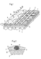
- Fig. 1 eine perspektivische, teilweise geschnittene Ansicht eines Ausschnitts aus dem erfindungsgemäßen Schleifwerkzeug im vergrößerten Maßstab,
- Fig. 2 einen Teilschnitt AB in weiter vergrößertem Maßstab und
- Fig. 3 bis 5 Diagramme zum Vergleich der Wirkungsweise des erfindungsgemäßen Schleifwerkzeugs mit dem Stand der Technik.
- 1 is a perspective, partially sectioned view of a section of the grinding tool according to the invention on an enlarged scale,
- Fig. 2 is a partial section AB in a further enlarged scale and
- 3 to 5 diagrams for comparing the operation of the grinding tool according to the invention with the prior art.
Das Schleifwerkzeug gemäß Fig. 1 umfaßt eine textile Unterlage, die aus einem Querfadengelege 1 und einem Längsfadengelege 2 besteht, die mittels Nähwirkfäden 3 als Nähgewirk zusammengesetzt sind. Die Textilschicht ist durch eine in der Zeichnung nicht in Erscheinung tretende Kernappretur in sich verfestigt, trägt auf der Vorderseite einer Kornschicht 4, die mittels einer Grundbindemittelschicht 5 und einer Deckbindemittelschicht 6 gebunden ist und ist auf der Rückseite mit einer Rückseitenappretur versehen, die lediglich in der linken Hälfte von Fig. 1 dargestellt ist. Zwischen der Berührungsebene der Faserstränge 1 und 2 und den höchsten Punkten der Nähwirkfäden 3 bilden sich Vertiefungen 8, die mit der Rückseitenappretur-Masse 7 ausgefüllt werden. Vorteilhafterweise ist die Rückseitenappretur derart ausgeführt, daß sie in den Zwischenräumen 8 eine wesentlich größere Dicke 9 aufweist als auf den überhöhten Stellen der Faserstränge 2 und der Nähfäden 3. Der Überschuß wird beim Aufbringen mittels eines Rakelmessers abgestrichen, so daß die höchsten Punkte der Fäden 3 nicht oder nur wenig von der Rückseitenappretur 7 bedeckt sind. Infolge Sedimentation reichern sich die Teilchen nahe der Unterlage im Bereich 12 ein wenig an, während der oberflächennahe Bereich 13 ärmer an Inhaltsstoff wird. Es findet anschließend teils beim Trocknen, teils durch Einziehen von Bindemittel in die Textilschicht ein gewisser Substanzvedust in der von der Rückseitenappretur gebildeten Schicht 7 statt, so daß diese in den Vertiefungen 8 ein wenig einfällt und die Wellenstruktur der Unterlage hervortritt. Dennoch sind die Zwischenräume stärker gefüllt als dies im Stand der Technik üblich ist Auch dies wirkt sich vorteilhaft auf die Steifigkeit des Produkts aus. Die höchsten Punkte der Fäden 3 treten entweder schon nach der Herstellung beschichtungsfrei hervor oder verlieren spätestens nach kurzer Betriebszeit infolge Verschleißes gemäß Linie 11 die auf ihnen befindliche, dünne Beschichtung und bilden dann Tragflächenelemente 10 für die Anlage derjenigen Schleifmaschinenstrukturen, die von der Rückseite her eine Pressung auf das Schieifband ausüben. In einem erfolgreich erprobten Beispiel wurde als Textilmaterial der Unterlage ein Nähwirkstoff verwendet, dessen Nähfäden in der Rückseite in regelmäßigen Abständen derart erscheinen, daß je ein solches Flächenelement 10 auf ein Raster von 1,7 x 1,1 mm kommt.1 comprises a textile underlay, which consists of a
Als Eisenglimmer hatsich im Zusammenhang mit der Erfindung das unter dem Warenzeichen MIOX der Firma Kärntner Montanindustrie GmbH, Klagenfurt, vertriebene Erzeugnis bewährt, dessen Partikel Durchmesser von durchschnittlich 40 um und Dicken von 2-4 µm aufweisen.In connection with the invention, the product sold under the trademark MIOX by Kärntner Montanindustrie GmbH, Klagenfurt, has proven to be iron mica, the particles of which have an average diameter of 40 .mu.m and thicknesses of 2-4 .mu.m.
Vergleichsversuche wurden durchgeführt mit zwei Schleifbändern, die übereinstimmten in der von einem Nähgewirk gebildeten Unterlage, Appretur und Komauftrag und sich lediglich dadurch unterschieden, daß das eine rückseitig in herkömmlicher Weise appretiert war, während das andere mit einer erfindungsgemäßen Rückseitenappretur versehen war. Diese bestand aus 50 Gewichtsteilen Phenolharz und 100 Gewichtsteilen Latex-Dispersion mit einem Festkörpergehalt von 25 Teilen sowie 20 Teilen Eisenglimmer MIOX der oben angegebenen Klassierung. Die Auftragsmenge betrug 25 g/m2 (trokken). Mit blo- ßem Auge war erkennbar, daß die Faserstrangzwischenräume der Schleifbandrückseite bei dem erfindungsgemäß appretierten Schleifband stärker gefüllt waren, wobei die Schichtdicke auf den Fasersträngen bzw. Nähfäden äußerst dünn war. Beide Bänder wurden unter praxisüblichen Bedingungen zum Schleifen von Holzspanplatten eingesetzt, wobei zur Erzeugung des Schleifdrucks in bekannter Weise ein Druckschuh eingesetzt wurde, der bandseits eine Filzschicht und darauf eine Graphitschicht trug, die die Gleitfläche für die Bandrückseite bildete. Wesentliche Ergebnisse dieser Vergleichsversuche sind in den Fig. 3 bis 5 dargestellt.Comparative tests were carried out with two abrasive belts, which corresponded in terms of the underlay, finish and grain application formed by a sewing fabric and differed only in that one was finished on the back in a conventional manner, while the other was provided with a backside finish according to the invention. This consisted of 50 parts by weight of phenolic resin and 100 parts by weight of latex dispersion with a solids content of 25 parts and 20 parts of MIOX iron mica of the classification given above. The amount applied was 25 g / m 2 (dry). It could be seen with the naked eye that the fiber strand interstices on the back of the abrasive belt were filled to a greater extent with the abrasive belt finished according to the invention, the layer thickness on the fiber strands or sewing threads being extremely thin. Both belts were used under normal conditions for sanding chipboard, whereby a pressure shoe was used in a known manner to generate the sanding pressure, which had a felt layer on the belt side and a graphite layer thereon, which formed the sliding surface for the belt back. The main results of these comparative tests are shown in FIGS. 3 to 5.
In Fig. 3 ist derAbrieb des Graphit in Gramm über der Schleifdauer in Stunden aufgetragen, und zwar für das herkömmliche Band in durchgezogener und für das erfindungsgemäße Band in gestrichelter Linie. Es zeigt sich, daß derAbrieb bei dem herkömmlichen Band wesentlich höher ist und auch nach der ersten halben Betriebsstunde noch beträchtlich ansteigt, während bei dem erfindungsgemäßen Band der Abrieb auf weniger als zwei Drittel reduziert ist und nach der ersten halben Betriebsstunde praktisch kein weiterer Abrieb mehr stattfindet.In Fig. 3, the abrasion of the graphite is plotted in grams over the grinding time in hours, for the conventional belt in a solid line and for the belt according to the invention in a broken line. It can be seen that the abrasion in the conventional belt is considerably higher and increases considerably even after the first half hour of operation, while the abrasion in the belt according to the invention is reduced to less than two thirds and practically no further abrasion takes place after the first half hour of operation .
Noch auffälliger ist die erfindungsgemäß erzielte Verringerung des Filzabriebs gemäß Fig. 4, in der die Massenabnahme des Filzes in Gramm über der Betriebsdauer in Stunden aufgetragen ist. Sie wird nämlich auf weniger als die Hälfte des herkömmlichen Filzverlustes reduziert.Even more striking is the reduction in felt wear according to FIG. 4, according to the invention, in which the decrease in mass of the felt in grams is plotted over the operating time in hours. It is reduced to less than half the conventional felt loss.
Dem entspricht die in Fig. 5 dargestellte Verringerung des Reibbeiwertes über der Betriebszeit. Während diese bei dem herkömmlichen Band nach einem Minimum, das nach etwa einer Stunde Betriebsdauer erreicht ist, wieder ansteigt, vermindert er sich bei dem erfindungsgemäßen Band zunehmend.This corresponds to the reduction in the coefficient of friction shown in FIG. 5 over the operating time. While this increases again in the conventional belt after a minimum which is reached after about an hour of operation, it decreases increasingly in the belt according to the invention.
Es wurde gemessen, daß dementsprechend auch die Temperatur an der Gleitfläche reduziert werden konnte. Während sie bei dem herkömmlichen Band auf etwa 240°C anstieg, erreichte sie bei dem erfindungsgemäßen Band nicht einmal 200°C.It was measured that the temperature on the sliding surface could accordingly be reduced. While it rose to around 240 ° C. in the conventional belt, it did not even reach 200 ° C. in the belt according to the invention.
Die Steifigkeit des erfindungsgemäßen Bands war beträchtlich größer als die des herkömmlichen.The stiffness of the tape according to the invention was considerably greater than that of the conventional one.
Claims (10)
Priority Applications (2)
| Application Number | Priority Date | Filing Date | Title |
|---|---|---|---|
| AT89104191T ATE63076T1 (en) | 1988-03-14 | 1989-03-09 | FLEXIBLE GRINDING TOOL. |
| DE8916124U DE8916124U1 (en) | 1988-03-14 | 1989-03-09 | Flexible grinding tool |
Applications Claiming Priority (2)
| Application Number | Priority Date | Filing Date | Title |
|---|---|---|---|
| DE3808426A DE3808426C2 (en) | 1988-03-14 | 1988-03-14 | Flexible grinding tool and process for its manufacture |
| DE3808426 | 1988-03-14 |
Publications (3)
| Publication Number | Publication Date |
|---|---|
| EP0333035A1 EP0333035A1 (en) | 1989-09-20 |
| EP0333035B1 true EP0333035B1 (en) | 1991-05-02 |
| EP0333035B2 EP0333035B2 (en) | 1999-06-23 |
Family
ID=6349670
Family Applications (1)
| Application Number | Title | Priority Date | Filing Date |
|---|---|---|---|
| EP89104191A Expired - Lifetime EP0333035B2 (en) | 1988-03-14 | 1989-03-09 | Flexible grinding tool |
Country Status (7)
| Country | Link |
|---|---|
| US (1) | US4960442A (en) |
| EP (1) | EP0333035B2 (en) |
| AT (1) | ATE63076T1 (en) |
| AU (1) | AU607058B2 (en) |
| CA (1) | CA1314710C (en) |
| DE (2) | DE3808426C2 (en) |
| ES (1) | ES2022732T5 (en) |
Families Citing this family (11)
| Publication number | Priority date | Publication date | Assignee | Title |
|---|---|---|---|---|
| US4925457B1 (en) * | 1989-01-30 | 1995-09-26 | Ultimate Abrasive Syst Inc | Method for making an abrasive tool |
| US6406577B1 (en) | 1991-12-20 | 2002-06-18 | 3M Innovative Properties Company | Method of making abrasive belt with an endless, seamless backing |
| US6406576B1 (en) | 1991-12-20 | 2002-06-18 | 3M Innovative Properties Company | Method of making coated abrasive belt with an endless, seamless backing |
| RU2116186C1 (en) * | 1991-12-20 | 1998-07-27 | Миннесота Майнинг Энд Мэнюфекчуринг Компани | Band with abrasive coating |
| US5681612A (en) * | 1993-06-17 | 1997-10-28 | Minnesota Mining And Manufacturing Company | Coated abrasives and methods of preparation |
| AU1735295A (en) * | 1994-02-22 | 1995-09-04 | Minnesota Mining And Manufacturing Company | Method for making an endless coated abrasive article and the product thereof |
| US5578096A (en) * | 1995-08-10 | 1996-11-26 | Minnesota Mining And Manufacturing Company | Method for making a spliceless coated abrasive belt and the product thereof |
| US20020146963A1 (en) * | 2001-02-08 | 2002-10-10 | 3M Innovative Properties Company | Composition containing graphite |
| US20030186630A1 (en) * | 2002-03-29 | 2003-10-02 | Lam Research Corporation | Reinforced chemical mechanical planarization belt |
| US7497768B2 (en) * | 2005-08-11 | 2009-03-03 | 3M Innovative Properties Company | Flexible abrasive article and method of making |
| US11890723B2 (en) * | 2015-05-08 | 2024-02-06 | Mirka Ltd | Abrasive belt grinding product |
Family Cites Families (16)
| Publication number | Priority date | Publication date | Assignee | Title |
|---|---|---|---|---|
| GB900867A (en) * | 1959-07-27 | 1962-07-11 | George Conrad Riegger | Sandpaper |
| US3163968A (en) * | 1962-12-31 | 1965-01-05 | Roscoe E Nafus | Graphite coated abrasive belts |
| US3942959A (en) * | 1967-12-22 | 1976-03-09 | Fabriksaktiebolaget Eka | Multilayered flexible abrasive containing a layer of electroconductive material |
| US4038047A (en) * | 1969-04-14 | 1977-07-26 | Norton Company | Method of making a flexible resilient abrasive |
| US3906684A (en) * | 1971-05-20 | 1975-09-23 | Norton Co | Abrasive articles and their method of manufacture |
| US4163647A (en) * | 1971-06-23 | 1979-08-07 | Norton Company | Method for producing coated abrasives |
| US3992178A (en) * | 1973-04-17 | 1976-11-16 | Fabrika Ab Eka | Flexible coated abrasive with graphite outer layer |
| CA1031967A (en) * | 1973-11-07 | 1978-05-30 | Jarvis M. Mcgarvey | Endless abrasive belt, and laminated patch splice therefor |
| US4111667A (en) * | 1977-04-15 | 1978-09-05 | Norton Company | Woven polyester backed flexible coated abrasive having microballoons in backsize |
| US4225321A (en) * | 1978-01-09 | 1980-09-30 | The Carborundum Company | Heat set and destretched polyester backing material in coated abrasive manufacture |
| EP0013486B1 (en) * | 1978-12-12 | 1983-08-03 | Interface Developments Limited | Flexible abrasive member and method of making same |
| US4255164A (en) * | 1979-04-30 | 1981-03-10 | Minnesota Mining And Manufacturing Company | Fining sheet and method of making and using the same |
| DE2918103C2 (en) * | 1979-05-04 | 1985-12-05 | Sia Schweizer Schmirgel- & Schleifindustrie Ag, Frauenfeld | Method for applying a base binder and apparatus for carrying out the same |
| US4543106A (en) * | 1984-06-25 | 1985-09-24 | Carborundum Abrasives Company | Coated abrasive product containing hollow microspheres beneath the abrasive grain |
| EP0197083A1 (en) * | 1984-10-09 | 1986-10-15 | Minnesota Mining And Manufacturing Company | Coated abrasive sheet material with improved backing |
| JPS62246476A (en) * | 1986-04-18 | 1987-10-27 | Fuji Photo Film Co Ltd | Manufacture of polishing tape |
-
1988
- 1988-03-14 DE DE3808426A patent/DE3808426C2/en not_active Revoked
-
1989
- 1989-03-09 ES ES89104191T patent/ES2022732T5/en not_active Expired - Lifetime
- 1989-03-09 AT AT89104191T patent/ATE63076T1/en not_active IP Right Cessation
- 1989-03-09 EP EP89104191A patent/EP0333035B2/en not_active Expired - Lifetime
- 1989-03-09 DE DE8989104191T patent/DE58900099D1/en not_active Expired - Fee Related
- 1989-03-14 US US07/323,314 patent/US4960442A/en not_active Expired - Lifetime
- 1989-03-14 AU AU31312/89A patent/AU607058B2/en not_active Ceased
- 1989-03-14 CA CA000593635A patent/CA1314710C/en not_active Expired - Fee Related
Also Published As
| Publication number | Publication date |
|---|---|
| ES2022732B3 (en) | 1991-12-01 |
| EP0333035A1 (en) | 1989-09-20 |
| ES2022732T5 (en) | 1999-11-01 |
| DE3808426C2 (en) | 1995-01-26 |
| AU3131289A (en) | 1989-09-14 |
| AU607058B2 (en) | 1991-02-21 |
| CA1314710C (en) | 1993-03-23 |
| ATE63076T1 (en) | 1991-05-15 |
| DE58900099D1 (en) | 1991-06-06 |
| US4960442A (en) | 1990-10-02 |
| DE3808426A1 (en) | 1989-09-28 |
| EP0333035B2 (en) | 1999-06-23 |
Similar Documents
| Publication | Publication Date | Title |
|---|---|---|
| EP0111765B1 (en) | Abrasive product with an extensible and flexible backing, method for its manufacture and its use | |
| EP0804316B1 (en) | Tool for mechanically treating surfaces | |
| EP0333035B1 (en) | Flexible grinding tool | |
| DE1937653A1 (en) | Tool for processing metal surfaces | |
| DE602005001842T2 (en) | GRINDING ELEMENT | |
| DE60030152T2 (en) | SLIP SPONGE WITH CARRIER WITH HIGH TENSILE STRENGTH | |
| EP0991500B1 (en) | Flexible abrasive body | |
| DE2008862A1 (en) | Fibrous fabrics and methods of making the same | |
| DE3029288A1 (en) | ROLLS COVERED WITH AN ELASTOMERIC MATERIAL AND METHOD FOR THEIR PRODUCTION | |
| CH647447A5 (en) | GRINDING MATERIAL. | |
| WO2003041899A1 (en) | Sawing wire | |
| DE2317507A1 (en) | LOW DENSITY GRINDING MATERIAL USING ISOCYANURATE RESIN | |
| DE102004039517B4 (en) | Cleaning cloth, process for making a cleaning cloth and its use | |
| EP1827762B1 (en) | Abrasive product and method for the production thereof | |
| DE102019127341A1 (en) | Method of manufacturing an abrasive unit | |
| DE60037239T2 (en) | abrasive | |
| DE2318108C3 (en) | Guide surface for the Fourdrinier of a paper machine | |
| WO2005110681A1 (en) | Mixed fibre material backing | |
| DE1168066B (en) | Process for the production of rubber belts provided with a fiber traction surface and belts produced according to this process | |
| EP0400766B1 (en) | Method for producing fibre mats containing a binding agent | |
| DE102005056368B4 (en) | Abrasive and process for its preparation | |
| DE3218441C1 (en) | Process for producing grinding tools in sheet or belt form | |
| DE4100167C2 (en) | ||
| DE1935137A1 (en) | Process for the production of abrasive cloth and a suitable base for it | |
| DE1502655C (en) | Grinding wheel, consisting of one or more layers of synthetic resin-bonded abrasive grains with reinforcement layers |
Legal Events
| Date | Code | Title | Description |
|---|---|---|---|
| PUAI | Public reference made under article 153(3) epc to a published international application that has entered the european phase |
Free format text: ORIGINAL CODE: 0009012 |
|
| AK | Designated contracting states |
Kind code of ref document: A1 Designated state(s): AT BE CH DE ES FR GB IT LI NL SE |
|
| 17P | Request for examination filed |
Effective date: 19890728 |
|
| GBC | Gb: translation of claims filed (gb section 78(7)/1977) | ||
| 17Q | First examination report despatched |
Effective date: 19900607 |
|
| GRAA | (expected) grant |
Free format text: ORIGINAL CODE: 0009210 |
|
| AK | Designated contracting states |
Kind code of ref document: B1 Designated state(s): AT BE CH DE ES FR GB IT LI NL SE |
|
| REF | Corresponds to: |
Ref document number: 63076 Country of ref document: AT Date of ref document: 19910515 Kind code of ref document: T |
|
| REF | Corresponds to: |
Ref document number: 58900099 Country of ref document: DE Date of ref document: 19910606 |
|
| ITF | It: translation for a ep patent filed |
Owner name: UFFICIO TECNICO ING. A. MANNUCCI |
|
| ET | Fr: translation filed | ||
| GBT | Gb: translation of ep patent filed (gb section 77(6)(a)/1977) | ||
| REG | Reference to a national code |
Ref country code: CH Ref legal event code: PFA Free format text: HERMES SCHLEIFMITTEL GMBH & CO. |
|
| RAP2 | Party data changed (patent owner data changed or rights of a patent transferred) |
Owner name: HERMES SCHLEIFMITTEL GMBH & CO. |
|
| PLBI | Opposition filed |
Free format text: ORIGINAL CODE: 0009260 |
|
| ITPR | It: changes in ownership of a european patent |
Owner name: CAMBIO RAGIONE SOCIALE;HERMES SCHLEIFMITTEL GMBH & |
|
| 26 | Opposition filed |
Opponent name: GUSTAV ERNSTMEIER GMBH & CO. KG Effective date: 19920201 |
|
| NLT1 | Nl: modifications of names registered in virtue of documents presented to the patent office pursuant to art. 16 a, paragraph 1 |
Owner name: HERMES SCHLEIFMITTEL GMBH & CO. TE HAMBURG, BONDSR |
|
| REG | Reference to a national code |
Ref country code: FR Ref legal event code: CD |
|
| NLR1 | Nl: opposition has been filed with the epo |
Opponent name: GUSTAV ERNSTMEIER GMBH & CO. KG. |
|
| REG | Reference to a national code |
Ref country code: ES Ref legal event code: PC2A Owner name: HERMES-SCHLEIFMITTEL GMBH & CO. |
|
| EAL | Se: european patent in force in sweden |
Ref document number: 89104191.5 |
|
| APAC | Appeal dossier modified |
Free format text: ORIGINAL CODE: EPIDOS NOAPO |
|
| APAC | Appeal dossier modified |
Free format text: ORIGINAL CODE: EPIDOS NOAPO |
|
| APAC | Appeal dossier modified |
Free format text: ORIGINAL CODE: EPIDOS NOAPO |
|
| PLAW | Interlocutory decision in opposition |
Free format text: ORIGINAL CODE: EPIDOS IDOP |
|
| PUAH | Patent maintained in amended form |
Free format text: ORIGINAL CODE: 0009272 |
|
| STAA | Information on the status of an ep patent application or granted ep patent |
Free format text: STATUS: PATENT MAINTAINED AS AMENDED |
|
| 27A | Patent maintained in amended form |
Effective date: 19990623 |
|
| AK | Designated contracting states |
Kind code of ref document: B2 Designated state(s): AT BE CH DE ES FR GB IT LI NL SE |
|
| GBTA | Gb: translation of amended ep patent filed (gb section 77(6)(b)/1977) | ||
| REG | Reference to a national code |
Ref country code: CH Ref legal event code: AEN Free format text: AUFRECHTERHALTUNG DES PATENTES IN GEAENDERTER FORM |
|
| NLR2 | Nl: decision of opposition | ||
| ITF | It: translation for a ep patent filed |
Owner name: UFFICIO TECNICO ING. A. MANNUCCI |
|
| ET3 | Fr: translation filed ** decision concerning opposition | ||
| REG | Reference to a national code |
Ref country code: ES Ref legal event code: DC2A Kind code of ref document: T5 Effective date: 19990915 |
|
| PGFP | Annual fee paid to national office [announced via postgrant information from national office to epo] |
Ref country code: ES Payment date: 20010326 Year of fee payment: 13 |
|
| REG | Reference to a national code |
Ref country code: GB Ref legal event code: IF02 |
|
| PGFP | Annual fee paid to national office [announced via postgrant information from national office to epo] |
Ref country code: GB Payment date: 20020214 Year of fee payment: 14 |
|
| PGFP | Annual fee paid to national office [announced via postgrant information from national office to epo] |
Ref country code: NL Payment date: 20020318 Year of fee payment: 14 Ref country code: FR Payment date: 20020318 Year of fee payment: 14 |
|
| PGFP | Annual fee paid to national office [announced via postgrant information from national office to epo] |
Ref country code: AT Payment date: 20020322 Year of fee payment: 14 |
|
| PGFP | Annual fee paid to national office [announced via postgrant information from national office to epo] |
Ref country code: SE Payment date: 20020325 Year of fee payment: 14 Ref country code: CH Payment date: 20020325 Year of fee payment: 14 Ref country code: BE Payment date: 20020325 Year of fee payment: 14 |
|
| PG25 | Lapsed in a contracting state [announced via postgrant information from national office to epo] |
Ref country code: GB Free format text: LAPSE BECAUSE OF NON-PAYMENT OF DUE FEES Effective date: 20030309 Ref country code: AT Free format text: LAPSE BECAUSE OF NON-PAYMENT OF DUE FEES Effective date: 20030309 |
|
| PG25 | Lapsed in a contracting state [announced via postgrant information from national office to epo] |
Ref country code: SE Free format text: LAPSE BECAUSE OF NON-PAYMENT OF DUE FEES Effective date: 20030310 Ref country code: ES Free format text: LAPSE BECAUSE OF NON-PAYMENT OF DUE FEES Effective date: 20030310 |
|
| PG25 | Lapsed in a contracting state [announced via postgrant information from national office to epo] |
Ref country code: LI Free format text: LAPSE BECAUSE OF NON-PAYMENT OF DUE FEES Effective date: 20030331 Ref country code: CH Free format text: LAPSE BECAUSE OF NON-PAYMENT OF DUE FEES Effective date: 20030331 Ref country code: BE Free format text: LAPSE BECAUSE OF NON-PAYMENT OF DUE FEES Effective date: 20030331 |
|
| BERE | Be: lapsed |
Owner name: *HERMES SCHLEIFMITTEL G.M.B.H. & CO. Effective date: 20030331 |
|
| PG25 | Lapsed in a contracting state [announced via postgrant information from national office to epo] |
Ref country code: NL Free format text: LAPSE BECAUSE OF NON-PAYMENT OF DUE FEES Effective date: 20031001 |
|
| GBPC | Gb: european patent ceased through non-payment of renewal fee |
Effective date: 20030309 |
|
| EUG | Se: european patent has lapsed | ||
| REG | Reference to a national code |
Ref country code: CH Ref legal event code: PL |
|
| PG25 | Lapsed in a contracting state [announced via postgrant information from national office to epo] |
Ref country code: FR Free format text: LAPSE BECAUSE OF NON-PAYMENT OF DUE FEES Effective date: 20031127 |
|
| NLV4 | Nl: lapsed or anulled due to non-payment of the annual fee |
Effective date: 20031001 |
|
| REG | Reference to a national code |
Ref country code: FR Ref legal event code: ST |
|
| REG | Reference to a national code |
Ref country code: ES Ref legal event code: FD2A Effective date: 20030310 |
|
| PG25 | Lapsed in a contracting state [announced via postgrant information from national office to epo] |
Ref country code: IT Free format text: LAPSE BECAUSE OF NON-PAYMENT OF DUE FEES;WARNING: LAPSES OF ITALIAN PATENTS WITH EFFECTIVE DATE BEFORE 2007 MAY HAVE OCCURRED AT ANY TIME BEFORE 2007. THE CORRECT EFFECTIVE DATE MAY BE DIFFERENT FROM THE ONE RECORDED. Effective date: 20050309 |
|
| APAH | Appeal reference modified |
Free format text: ORIGINAL CODE: EPIDOSCREFNO |
|
| PGFP | Annual fee paid to national office [announced via postgrant information from national office to epo] |
Ref country code: DE Payment date: 20060522 Year of fee payment: 18 |
|
| PG25 | Lapsed in a contracting state [announced via postgrant information from national office to epo] |
Ref country code: DE Free format text: LAPSE BECAUSE OF NON-PAYMENT OF DUE FEES Effective date: 20071002 |