EP0332832B1 - Einwegkamera und elektronische Blitzlichteinheit als wiederverwendbares Zusatzgerät - Google Patents
Einwegkamera und elektronische Blitzlichteinheit als wiederverwendbares Zusatzgerät Download PDFInfo
- Publication number
- EP0332832B1 EP0332832B1 EP89101895A EP89101895A EP0332832B1 EP 0332832 B1 EP0332832 B1 EP 0332832B1 EP 89101895 A EP89101895 A EP 89101895A EP 89101895 A EP89101895 A EP 89101895A EP 0332832 B1 EP0332832 B1 EP 0332832B1
- Authority
- EP
- European Patent Office
- Prior art keywords
- shutter
- flash
- flash unit
- access ports
- sealed pack
- Prior art date
- Legal status (The legal status is an assumption and is not a legal conclusion. Google has not performed a legal analysis and makes no representation as to the accuracy of the status listed.)
- Expired - Lifetime
Links
- 239000000463 material Substances 0.000 claims description 4
- 235000010724 Wisteria floribunda Nutrition 0.000 description 2
- 238000010304 firing Methods 0.000 description 2
- 230000000881 depressing effect Effects 0.000 description 1
- 238000012986 modification Methods 0.000 description 1
- 230000004048 modification Effects 0.000 description 1
- 230000000717 retained effect Effects 0.000 description 1
Images


Classifications
-
- G—PHYSICS
- G03—PHOTOGRAPHY; CINEMATOGRAPHY; ANALOGOUS TECHNIQUES USING WAVES OTHER THAN OPTICAL WAVES; ELECTROGRAPHY; HOLOGRAPHY
- G03B—APPARATUS OR ARRANGEMENTS FOR TAKING PHOTOGRAPHS OR FOR PROJECTING OR VIEWING THEM; APPARATUS OR ARRANGEMENTS EMPLOYING ANALOGOUS TECHNIQUES USING WAVES OTHER THAN OPTICAL WAVES; ACCESSORIES THEREFOR
- G03B19/00—Cameras
- G03B19/02—Still-picture cameras
- G03B19/04—Roll-film cameras
-
- G—PHYSICS
- G03—PHOTOGRAPHY; CINEMATOGRAPHY; ANALOGOUS TECHNIQUES USING WAVES OTHER THAN OPTICAL WAVES; ELECTROGRAPHY; HOLOGRAPHY
- G03B—APPARATUS OR ARRANGEMENTS FOR TAKING PHOTOGRAPHS OR FOR PROJECTING OR VIEWING THEM; APPARATUS OR ARRANGEMENTS EMPLOYING ANALOGOUS TECHNIQUES USING WAVES OTHER THAN OPTICAL WAVES; ACCESSORIES THEREFOR
- G03B15/00—Special procedures for taking photographs; Apparatus therefor
- G03B15/02—Illuminating scene
- G03B15/03—Combinations of cameras with lighting apparatus; Flash units
- G03B15/05—Combinations of cameras with electronic flash apparatus; Electronic flash units
-
- G—PHYSICS
- G03—PHOTOGRAPHY; CINEMATOGRAPHY; ANALOGOUS TECHNIQUES USING WAVES OTHER THAN OPTICAL WAVES; ELECTROGRAPHY; HOLOGRAPHY
- G03B—APPARATUS OR ARRANGEMENTS FOR TAKING PHOTOGRAPHS OR FOR PROJECTING OR VIEWING THEM; APPARATUS OR ARRANGEMENTS EMPLOYING ANALOGOUS TECHNIQUES USING WAVES OTHER THAN OPTICAL WAVES; ACCESSORIES THEREFOR
- G03B2215/00—Special procedures for taking photographs; Apparatus therefor
- G03B2215/05—Combinations of cameras with electronic flash units
- G03B2215/0514—Separate unit
- G03B2215/056—Connection with camera, e.g. adapter
-
- G—PHYSICS
- G03—PHOTOGRAPHY; CINEMATOGRAPHY; ANALOGOUS TECHNIQUES USING WAVES OTHER THAN OPTICAL WAVES; ELECTROGRAPHY; HOLOGRAPHY
- G03B—APPARATUS OR ARRANGEMENTS FOR TAKING PHOTOGRAPHS OR FOR PROJECTING OR VIEWING THEM; APPARATUS OR ARRANGEMENTS EMPLOYING ANALOGOUS TECHNIQUES USING WAVES OTHER THAN OPTICAL WAVES; ACCESSORIES THEREFOR
- G03B2219/00—Cameras
- G03B2219/02—Still-picture cameras
- G03B2219/04—Roll-film cameras
- G03B2219/045—Roll-film cameras adapted for unloading the film in the processing laboratory, e.g. disposable, reusable or recyclable cameras
Definitions
- the invention relates generally to the field of photography, and more particularly to a disposable single-use camera and an accessory re-usable electronic flash unit intended for use with the disposable camera.
- each disposable camera is a point-and-shoot type and comprises (1) a plastic inner camera part including a taking lens, a film metering mechanism, and a shutter and (2) a cardboard outer sealed pack which contains the inner camera part and has respective openings for the taking lens and for a shutter release button, a frame counter window, a film advance thumbwheel, and a simple see-through viewfinder of the camera part.
- the inner camera part is loaded with a conventional 24-exposure 35mm film cartridge, and substantially the entire length of the unexposed filmstrip is factory prewound from the cartridge into a supply chamber of the camera part.
- the thumbwheel is manually rotated to rewind the exposed frame into the cartridge.
- the rewinding movement of the filmstrip the equivalent of one frame rotates a metering sprocket to decrement a frame counter to its next lower numbered setting.
- the single-use camera is sent to a photofinisher who first removes the inner camera part from the cardboard sealed pack and then removes the filmstrip from the camera part.
- the filmstrip is processed, and the camera part and the opened pack are thrown away.
- the above described problem associated with known disposable single-use cameras is believed solved by the invention.
- the invention provides a disposable single-use camera and an accessory re-usable electronic flash unit. Owing to the novel design of these two components, only the disposable camera need be returned to the photofinisher; the flash unit is retained by the customer for re-use with another disposable camera.
- an improved combination of a disposable single-use camera and an electronic flash unit wherein (a) an inner camera part is pre-loaded with film and includes a taking lens and a shutter and (b) an outer sealed pack contains said camera part and has an opening for said taking lens, and wherein the improvement comprises: said inner camera part has flash synchronization access ports; said outer sealed pack is constructed of a perforable material which overlies said access ports; and said flash unit includes electrically conductive flash synchronization pins shaped to perforate said outer sealed pack to enter said access ports, whereby the flash unit is removably connected to said inner camera part.
- the invention is disclosed in connection with a 35mm camera and an electronic flash unit. Because such a camera and flash unit are widely known, this description is directed in particular to photographic elements forming part of or cooperating directly with the invention. It is to be understood, however, that other elements not specifically shown or described may take various forms known to persons of ordinary still in the art.
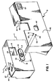
- FIG. 1 depicts a disposable single-use 35mm camera 1 and an accessory re-usable electronic flash unit 3.
- the disposable camera 1 is a point-and-shoot type and comprises (1) an inner camera part 5 including a taking lens 7, a film metering mechanism (not shown), and a single blade shutter 9 and (2) an outer sealed pack 11 which contains the inner camera part and has respective openings 13, 15, 17, 19, and 21 for the taking lens, a shutter release button 23, a frame counter window 25, a film advance thumbwheel 27, and a direct see-through viewfinder 29.
- the release button 23, the counter window 25, the thumbwheel 27, and the viewfinder 29, like the taking lens 7, are located on the inner camera part 5.
- the outer sealed pack 11 is decorative in nature and is constructed of a paper-like material, such as cardboard.
- the inner camera part 5 is constructed of plastic.
- the inner camera part 5 is loaded with a conventional 24-exposure 35mm film cartridge and substantially the entire length of the unexposed filmstrip is factory prewound from the cartridge onto a take-up spool (not shown) of the camera part.
- the thumbwheel 27 is manually rotated to rewind the exposed frame into the cartridge.
- the rewinding movement of the filmstrip the equivalent of one frame rotates a metering sprocket (not shown) to decrement a frame counter (not shown) to its next lower numbered setting.
- the single-use camera 1 is sent to a photofinisher who first removes the inner camera part 5 from the cardboard sealed pack 11 and then removes the filmstrip from the camera part. The filmstrip is processed, and the camera part and the opened pack are thrown away.
- the inner camera part 5 has a pair of flash synchronization access ports or openings 31 and 33 which extend through a front face 35 of the camera part at a location proximate the taking lens 7.
- the respective access ports 31 and 33 are aligned with corresponding recesses 37 and 39 which, as can be seen in FIG. 4, are located proximate the single blade shutter 9.
- the two access ports 31 and 33 are covered by the outer sealed pack 11. See FIG. 1.
- the re-usable flash unit 3 in addition to having a conventional flash emission device 41, includes an integral shell-like portion 43 which is dimensioned to fit over the single-use camera 1 in the manner shown in FIG. 1.
- a front wall 45 of the shell-like portion 43 has an opening 47 for the taking lens 7.
- Respective supports 49 and 51 for a pair of electrically conductive flash synchronization pins 53 and 55 are located on the inside of the front wall 45.
- the two conductive pins 53 and 55 have pointed tips to enable them to readily perforate the outer sealed pack 11.
- a flash window 57 of the flash emission device 41 is positioned in proper relation with the taking lens 7 for a flash exposure and the two conductive pins 53 and 55 are driven or forced through the outer sealed pack 11, directly into the respective access ports 31 and 33.
- the two conductive pins 53 and 55 then bottom out in the respective recesses 37 and 39. See FIG. 4.
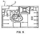
- the shutter blade 9 is electrically conductive and is mounted for pivotable movement about a fixed pin 59, against the surging of an electrically conductive return spring 61, from a closed position shown in FIG. 4 to a fully opened position shown in FIG. 5.
- the access port 33 and its corresponding recess 39 are arranged to position the conductive pin 55 in continuous contact with one leg 63 of the return spring 61.
- Another leg 65 of the return spring 61 is connected to the shutter blade 9.
- the access port 31 and its corresponding recess 37 are arranged to position the conductive pin 53 in contact with the shutter blade 9 only when the shutter blade is fully opened.
- a pivotally mounted locking/switching member 67 which, when swung from its illustrated position to an intermediate broken line position 67a, partially covers the rear of the single-use camera 1 to secure the shell-like portion 43 to the single-use camera, and which, when swung from the intermediate broken line position to a final broken line position 67b, closes a conventional normally opened flash energizing switch 69 to ready the flash emission device 41 for firing when the shutter blade 9 is fully opened.
- the locking/switching member 67 includes a cam element 71 for closing the flash energizing switch 69 and has three v-shaped cut-outs 73, 75, and 77 respectively engageable with a spring urged arresting element 81 to releasably secure the locking/switching member 67 in its three positions.
- the flash window 57 is positioned in proper relation with the taking lens 7 for a flash exposure and the two conductive pins 53 and 55 are driven through the outer sealed pack 11, directly into the respective access ports 31 and 33.
- the two conductive pins 53 and 55 then bottom out in the respective recesses 37 and 39. See FIG. 4.
- the locking/switching member 67 is swung from its illustrated position in FIG. 2 to the intermediate broken line position 67a in that FIG.
- the locking/switching member 67 is swung from its intermediate broken line position 67a in FIG. 2 to the final broken line position 67b in that FIG. to close the flash energizing switch 69.
- the flash emission device 41 is automatically fired. Since the flash output reaches its peak almost immediately, i.e. there is no firing delay, the maximum brilliance of the flash light coincides with full opening of the shutter blade 9.
- the locking/switching member 67 is left in its intermediate broken line position 67a. Then, when the shutter blade 9 is fully opened, the flash emission device 41 is not fired.
Landscapes
- Physics & Mathematics (AREA)
- General Physics & Mathematics (AREA)
- Stroboscope Apparatuses (AREA)
- Structure And Mechanism Of Cameras (AREA)
- Blocking Light For Cameras (AREA)
Claims (10)
- Aus einer Einwegkamera (1) und einer elektronischen Blitzeinheit (3) bestehende Kombination mit einem inneren vorab mit Film geladenen Kamerateil (5), einem Aufnahmeobjektiv (7) und einem Verschluß (9) sowie mit einer äußeren versiegelten Umhüllung (11), die das Kamerateil enthält und eine Öffnung (13) für das Aufnahmeobjektiv aufweist, dadurch gekennzeichnet, daß
das innere Kamerateil (5) Anschlußbuchsen (31, 33) für die Blitzsynchronisation ausweist,
die äußere versiegelte Umhüllung aus einem durchstechbaren Material (35) besteht, das die Anschlußbuchsen (31, 33) überdeckt, und
die Blitzeinheit (3) elektrisch leitfähige Kontaktstifte (53, 55) für die Blitzsynchronisation aufweist, die so ausgebildet sind, daß sie die äußere versiegelte Umhüllung (11) durchstoßen und zur lösbaren Verbindung der Blitzeinheit mit dem inneren Kamerateil (5) in die Anschlußbuchsen (31, 33) eingesteckt werden können. - Kombination nach Anspruch 1, dadurch gekennzeichnet, daß mit der Blitzeinheit (3) einstückig eine Einrichtung (43) ausgebildet ist, die mit der äußeren versiegelten Umhüllung (11) kooperiert und so angeordnet ist, daß sie sich in einer für eine Blitzaufnahme erforderlichen Zuordnung zu dem Aufnahmeobjektiv (7) befindet, und daß die leitfähigen Kontaktstifte (53, 55) die versiegelte Umhüllung durchstoßen und in die Anschlußbuchsen (31, 33) eingreifen.
- Kombination nach Anspruch 1, dadurch gekennzeichnet, daß die einstückig ausgebildete Einrichtung (43) aus einem schalenförmigen Element (43) besteht, das so geformt ist, daß es auf und teilweise über die äußere versiegelte Umhüllung (11) paßt, und das eine Öffnung (47) für das Aufnahmeobjektiv (7) und entsprechende Anschlüse (49, 51) für die leitfähigen Kontaktstifte besitzt.
- Kombination nach Anspruch 2 oder 3, dadurch gekennzeichnet, daß der Verschluß (9) elektrisch leitfähig und so gelagert ist, daß er vollständig in eine Offenstellung bewegbar ist, daß eine elektrisch leitfähige Rückstellfeder (61) mit dem Verschluß verbunden ist, daß eine (33) der Anschlußbuchsen so angeordnet ist, daß einer der leitfähigen Kontaktstifte (55) in ihr in ständigem Kontakt mit der Rückstellfeder steht und daß die andere Anschlußbuchse (31) derart angeordnet ist, daß sie einen in ihr befindlichen leitfähigen Kontaktstift (53) nur mit dem vollständig geöffneten Verschluß in Berührung hält.
- Eine als Zubehörteil vorgesehene, wiederholt verwendbare elektronische Blitzeinheit (3) für eine Einwegkamera (1), die ein inneres vorab mit Film geladenes Kamerateil (5), ein Aufnahmeobjektiv (7), einen Verschluß und Anschlußbuchsen (31, 33) für die Blitzsynchronisation sowie eine die Anschlußbuchsen abdeckende äußere versiegelte und durchstechbare Umhüllung (11) aufweist, die das innere Kamerateil enthält und eine Öffnung (13) für das Aufnahmeobjektiv besitzt, dadurch gekennzeichnet, daß
elektrisch leitfähige Kontaktstifte (53, 55) für die Blitzsynchronisation so ausgebildet sind, daß sie beim Einstecken in die Anschlußbuchsen (31, 33) zur lösbaren Verbindung der Blitzeinheit (3) mit dem inneren Kamerateil (5) die äußere versiegelte Umhüllung (11) durchstechen. - Elektronische Blitzeinheit (3) nach Anspruch 5, dadurch gekennzeichnet, daß einstückig mit der Blitzeinheit eine Einrichtung (43) ausgebildet ist, die die Blitzeinheit gegenüber der äußeren versiegelten Umhüllung (11) derart ausrichtet, daß sie sich in einer derartigen für eine Blitzaufnahme geeigneten Zuordnung zum Aufnahmeobjektiv (7) befindet, daß die leitfähigen Kontaktstifte (53, 55) durch die versiegelte Umhüllung hindurch in die Anschlußbuchsen (31, 33) eingreifen.
- Elektronische Blitzeinheit nach Anspruch 6, dadurch gekennzeichnet, daß die einstückig ausgebildete Einrichtung (43) ein schalenartiges Element (43) ist, das auf und teilweise über die äußere versiegelte Umhüllung (11) paßt und eine Öffnung (47) für das Aufnahmeobjektiv (7) und entsprechende Anschlüsse (49, 51) für die leitfähigen Kontaktstifte besitzt.
- Einwegkamera (1) zur Verwendung mit einer elektronischen Blitzeinheit (3) mit elektrisch leitfähigen Kontaktstiften (53, 55) für die Blitzsynchronisation, wobei die Kamera ein vorab mit Film geladenes inneres Kamerateil (5) umfaßt und ein Aufnahmeobjektiv (7) und einen Verschluß (9) besitzt sowie eine äußere versiegelte Umhüllung (11) aufweist, die das Kamerateil enthält und mit einer Öffnung (13) für das Aufnahmeobjektiv versehen ist, dadurch gekennzeichnet, daß
die äußere versiegelte Umhüllung (11) aus einem von den leitfähigen Kontaktstiften (53, 55) durchstechbaren Material (35) besteht und
daß das innere Kamerateil (5) Anschlußbuchsen (31, 33) für die Blitzsynchronisation aufweist, die unmittelbar hinter der äußeren versiegelten Umhüllung (11) so angeordnet sind, daß die leitfähigen Kontaktstifte (53, 55) nach dem Durchstechen der versiegelten Umhüllung in sie eingreifen. - Kamera (1) nach Anspruch 8, dadurch gekennzeichnet, daß der Verschluß (9) elektrisch leitfähig und so gelagert ist, daß er vollständig in eine Offenstellung bewegbar ist, daß eine elektrisch leitfähige Rückstellfeder (61) mit dem Verschluß verbunden ist, eine (33) der Anschlußbuchsen so angeordnet ist, daß ein in der Buchse befindlicher leitfähiger Kontaktstift (55) in ständigem Kontakt mit der Rückstellfeder gehalten ist, und die andere Anschlußbuchse (31) so angeordnet ist, daß ein in ihr befindlicher leitfähiger Kontaktstift (53) nur mit dem vollständig geöffneten Verschluß in Berührung steht.
- Vorrichtung nach den Ansprüchen 1 oder 5, dadurch gekennzeichnet, daß die Blitzeinheit (3) ein hinteres Rast-/Schaltelement (67) aufweist, das in eine Raststellung bewegbar ist, in der es die Rückseite der Kamera (1) teilweise abdeckt und so die Blitzeinheit an der Kamera befestigt, sowie in eine weitere Schaltstellung, in der es einen normalerweise geöffneten Blitzschalter (69) der Blitzeinheit zur Blitzauslösung schließt.
Applications Claiming Priority (2)
| Application Number | Priority Date | Filing Date | Title |
|---|---|---|---|
| US07/157,239 US4801957A (en) | 1988-02-18 | 1988-02-18 | Disposable single-use camera and accessory re-usable electronic flash unit |
| US157239 | 1988-02-18 |
Publications (3)
| Publication Number | Publication Date |
|---|---|
| EP0332832A2 EP0332832A2 (de) | 1989-09-20 |
| EP0332832A3 EP0332832A3 (en) | 1989-10-18 |
| EP0332832B1 true EP0332832B1 (de) | 1993-05-05 |
Family
ID=22562904
Family Applications (1)
| Application Number | Title | Priority Date | Filing Date |
|---|---|---|---|
| EP89101895A Expired - Lifetime EP0332832B1 (de) | 1988-02-18 | 1989-02-03 | Einwegkamera und elektronische Blitzlichteinheit als wiederverwendbares Zusatzgerät |
Country Status (5)
| Country | Link |
|---|---|
| US (1) | US4801957A (de) |
| EP (1) | EP0332832B1 (de) |
| JP (1) | JP2783828B2 (de) |
| DE (1) | DE68906296T2 (de) |
| ES (1) | ES2040906T3 (de) |
Families Citing this family (80)
| Publication number | Priority date | Publication date | Assignee | Title |
|---|---|---|---|---|
| FR2616232B1 (fr) * | 1987-06-05 | 1991-05-24 | Fuji Photo Film Co Ltd | Flash electronique et ensemble photographique jetable le comportant |
| DE3905310C2 (de) * | 1988-02-22 | 2003-02-27 | Fuji Photo Film Co Ltd | Einwegkamera |
| USD321705S (en) | 1988-08-31 | 1991-11-19 | Fuji Photo Film Co., Ltd. | Disposable camera |
| US4882600A (en) * | 1989-04-07 | 1989-11-21 | Eastman Kodak Company | Underwater disposable single-use camera |
| US4901097A (en) * | 1989-04-07 | 1990-02-13 | Eastman Kodak Company | Disposable single-use camera with lens shade |
| US5045871A (en) * | 1989-06-30 | 1991-09-03 | Reinholdson Mark R | Disposable camera |
| US4973998A (en) * | 1990-01-16 | 1990-11-27 | Eastman Kodak Company | Disposable single-use camera and accessory re-usable electronic flash unit |
| US5021811A (en) * | 1990-06-21 | 1991-06-04 | Eastman Kodak Company | Recycleable element recycle counter and method |
| EP0465897B1 (de) * | 1990-07-09 | 1997-09-10 | Fuji Photo Film Co., Ltd. | Mit einem Objektiv bestückter Hauptkörper einer Kamera |
| USD332109S (en) | 1990-08-01 | 1992-12-29 | Fuji Photo Film Co., Ltd. | Disposable camera |
| USD330563S (en) | 1990-08-02 | 1992-10-27 | Fuji Photo Film Co., Ltd. | Disposable camera |
| USD330564S (en) | 1990-08-02 | 1992-10-27 | Fuji Photo Film Co., Ltd. | Disposable camera |
| USD328911S (en) | 1990-08-07 | 1992-08-25 | Fuji Photo Film Co., Ltd. | Disposable camera |
| US5146256A (en) * | 1991-02-19 | 1992-09-08 | Eastman Kodak Company | Close-up attachment for single-use camera |
| JP2914587B2 (ja) * | 1991-04-19 | 1999-07-05 | 富士写真フイルム株式会社 | レンズ付きフイルムユニット及びその製造方法 |
| US5189453A (en) * | 1991-04-19 | 1993-02-23 | Eastman Kodak Company | Method and system for pre-exposing information on a filmstrip |
| USD328912S (en) | 1991-08-13 | 1992-08-25 | Fuji Photo Film Co., Ltd. | Disposable camera |
| JP3289109B2 (ja) * | 1991-10-18 | 2002-06-04 | コニカ株式会社 | 撮影ユニット |
| US5187512A (en) * | 1991-10-21 | 1993-02-16 | Polaroid Corporation | Film cassette containing pre-exposed film |
| US5335033A (en) * | 1992-07-23 | 1994-08-02 | Eastman Kodak Company | Lensless camera viewfinder |
| USD338220S (en) | 1992-10-15 | 1993-08-10 | Fuji Photo Film Co., Ltd. | Camera |
| JP2865504B2 (ja) * | 1992-11-16 | 1999-03-08 | 富士写真フイルム株式会社 | 包装体の分離方法 |
| USD352303S (en) | 1993-05-14 | 1994-11-08 | Eastman Kodak Company | Single-use camera with built-in flash |
| USD353607S (en) | 1993-07-01 | 1994-12-20 | Fuji Photo Film Co., Ltd. | Single use camera |
| US5384613A (en) * | 1994-01-14 | 1995-01-24 | Eastman Kodak Company | Single-use camera with weakened area to access film cassette |
| USD363078S (en) | 1994-03-31 | 1995-10-10 | Fuji Photo Film Co., Ltd. | Single use camera |
| USD359745S (en) | 1994-04-06 | 1995-06-27 | Fuji Photo Film Co., Ltd. | Single-use camera |
| US5765062A (en) * | 1994-04-19 | 1998-06-09 | Keepsake, Inc. | Reusable fun photography double exposure camera |
| US5546146A (en) * | 1994-04-19 | 1996-08-13 | Keepsake, Inc. | Single use camera film pre-exposure method |
| US5875362A (en) * | 1995-12-28 | 1999-02-23 | Eastman Kodak Company | Single-use flash camera with emergency strobe or continuous illumination enhancements |
| US5615396A (en) * | 1996-06-25 | 1997-03-25 | Photo Dimensions | Producing smoothly blended double exposure composite images |
| US5835795A (en) * | 1996-06-25 | 1998-11-10 | Photo Dimensions | Blended photographic composite images |
| US5748987A (en) * | 1996-06-25 | 1998-05-05 | Photo Dimensions | Producing smoothly blended double exposure composite images |
| USD410481S (en) * | 1997-05-13 | 1999-06-01 | Ronald G. Roncal | Photography booth |
| US6304730B1 (en) | 1999-04-29 | 2001-10-16 | Eastman Kodak Company | Film cassette having an indication of underexposure |
| US6485461B1 (en) | 2000-04-04 | 2002-11-26 | Insulet, Inc. | Disposable infusion device |
| US6669669B2 (en) | 2001-10-12 | 2003-12-30 | Insulet Corporation | Laminated patient infusion device |
| DE60128826T2 (de) * | 2000-09-08 | 2008-02-07 | Insulet Corp., Beverly | Infusionsvorrichtung und System |
| DE60135042D1 (de) | 2000-11-09 | 2008-09-04 | Insulet Corp | Gerät zur transkutanen Abgabe von Medikamenten |
| US6768425B2 (en) | 2000-12-21 | 2004-07-27 | Insulet Corporation | Medical apparatus remote control and method |
| CN1556716A (zh) | 2001-02-22 | 2004-12-22 | ���Ͽع�����˾ | 模块化的输注装置和方法 |
| US20040078028A1 (en) * | 2001-11-09 | 2004-04-22 | Flaherty J. Christopher | Plunger assembly for patient infusion device |
| US6692457B2 (en) | 2002-03-01 | 2004-02-17 | Insulet Corporation | Flow condition sensor assembly for patient infusion device |
| US6830558B2 (en) | 2002-03-01 | 2004-12-14 | Insulet Corporation | Flow condition sensor assembly for patient infusion device |
| US6839510B2 (en) * | 2002-03-28 | 2005-01-04 | Fuji Photo Film Co., Ltd. | Lens-fitted photo film unit, flash device, and lens-fitted photo film system |
| US20040153032A1 (en) * | 2002-04-23 | 2004-08-05 | Garribotto John T. | Dispenser for patient infusion device |
| US6656158B2 (en) | 2002-04-23 | 2003-12-02 | Insulet Corporation | Dispenser for patient infusion device |
| US20050238507A1 (en) * | 2002-04-23 | 2005-10-27 | Insulet Corporation | Fluid delivery device |
| US6656159B2 (en) | 2002-04-23 | 2003-12-02 | Insulet Corporation | Dispenser for patient infusion device |
| US6960192B1 (en) | 2002-04-23 | 2005-11-01 | Insulet Corporation | Transcutaneous fluid delivery system |
| JP3854190B2 (ja) * | 2002-04-26 | 2006-12-06 | 株式会社ジェイテクト | モータ制御装置 |
| US6723072B2 (en) | 2002-06-06 | 2004-04-20 | Insulet Corporation | Plunger assembly for patient infusion device |
| US7018360B2 (en) * | 2002-07-16 | 2006-03-28 | Insulet Corporation | Flow restriction system and method for patient infusion device |
| US7144384B2 (en) * | 2002-09-30 | 2006-12-05 | Insulet Corporation | Dispenser components and methods for patient infusion device |
| US7128727B2 (en) * | 2002-09-30 | 2006-10-31 | Flaherty J Christopher | Components and methods for patient infusion device |
| US20040116866A1 (en) * | 2002-12-17 | 2004-06-17 | William Gorman | Skin attachment apparatus and method for patient infusion device |
| US20050182366A1 (en) * | 2003-04-18 | 2005-08-18 | Insulet Corporation | Method For Visual Output Verification |
| US20050065760A1 (en) * | 2003-09-23 | 2005-03-24 | Robert Murtfeldt | Method for advising patients concerning doses of insulin |
| US20050070847A1 (en) * | 2003-09-29 | 2005-03-31 | Van Erp Wilhelmus Petrus Martinus Maria | Rapid-exchange balloon catheter with hypotube shaft |
| US20060178633A1 (en) * | 2005-02-03 | 2006-08-10 | Insulet Corporation | Chassis for fluid delivery device |
| US7552240B2 (en) * | 2005-05-23 | 2009-06-23 | International Business Machines Corporation | Method for user space operations for direct I/O between an application instance and an I/O adapter |
| ES2988610T3 (es) | 2012-03-30 | 2024-11-21 | Insulet Corp | Dispositivo de administración de fluido con herramienta de acceso transcutáneo, mecanismo de inserción y monitorización de glucemia para su uso con el mismo |
| USD709875S1 (en) * | 2013-03-15 | 2014-07-29 | Samsung Electronics Co., Ltd. | Electronic device |
| US10441717B2 (en) | 2014-04-15 | 2019-10-15 | Insulet Corporation | Monitoring a physiological parameter associated with tissue of a host to confirm delivery of medication |
| US10716896B2 (en) | 2015-11-24 | 2020-07-21 | Insulet Corporation | Wearable automated medication delivery system |
| WO2017091584A1 (en) | 2015-11-25 | 2017-06-01 | Insulet Corporation | Wearable medication delivery device |
| US10245377B2 (en) | 2016-11-11 | 2019-04-02 | Insulet Corporation | Drug delivery systems with sealed and sterile fluid paths and methods of providing the same |
| US11045603B2 (en) | 2017-02-22 | 2021-06-29 | Insulet Corporation | Needle insertion mechanisms for drug containers |
| US10722640B2 (en) | 2017-08-03 | 2020-07-28 | Insulet Corporation | Devices, systems, and methods of packaging for a pre-filled drug delivery device |
| US10973939B2 (en) | 2017-08-03 | 2021-04-13 | Insulet Corporation | System and method for aseptic packaging of a drug delivery device components |
| EP4306146A3 (de) | 2017-09-25 | 2024-01-24 | Insulet Corporation | Medikamentenabgabevorrichtung basierend auf vorgefüllter kartusche |
| EP3687600B1 (de) | 2017-09-26 | 2022-04-27 | Insulet Corporation | Nadelmechanismusmodul für wirkstofffreisetzungsvorrichtung |
| US11147931B2 (en) | 2017-11-17 | 2021-10-19 | Insulet Corporation | Drug delivery device with air and backflow elimination |
| US11241532B2 (en) | 2018-08-29 | 2022-02-08 | Insulet Corporation | Drug delivery system with sensor having optimized communication and infusion site |
| US12458751B2 (en) | 2020-10-02 | 2025-11-04 | Insulet Corporation | Fluid delivery device having multiple penetrating elements |
| WO2022133218A1 (en) | 2020-12-18 | 2022-06-23 | Insulet Corporation | Adhesive pad with a metallic coil for securing an on-body medical device |
| US12496398B2 (en) | 2021-05-28 | 2025-12-16 | Insulet Corporation | Threshold based automatic glucose control response |
| EP4346945A1 (de) | 2021-05-28 | 2024-04-10 | Insulet Corporation | Federbasierte statussensoren |
| US12406760B2 (en) | 2021-06-07 | 2025-09-02 | Insulet Corporation | Exercise safety prediction based on physiological conditions |
| US12478738B2 (en) | 2021-11-04 | 2025-11-25 | Insulet Corporation | Methods and systems for sterilizing sealed components of a drug delivery device |
Family Cites Families (8)
| Publication number | Priority date | Publication date | Assignee | Title |
|---|---|---|---|---|
| DE1685596B2 (de) * | 1966-12-24 | 1978-06-29 | Schubert & Salzer Maschinenfabrik Ag, 8070 Ingolstadt | Arbeitsverfahren und Vorrichtung zum Zusammenstellen von Fasermischungen |
| DE2708895A1 (de) * | 1976-03-08 | 1977-09-15 | Itt Ind Gmbh Deutsche | Elektronenblitzzusatz |
| US4226517A (en) * | 1979-04-30 | 1980-10-07 | A 1000 Words Incorporated | Camera device |
| DE8330038U1 (de) * | 1983-03-21 | 1984-08-30 | W. Haking Enterprises, Ltd., Hongkong | Stehbildkamera mit einem kameragehaeuse |
| US4666274A (en) * | 1984-10-05 | 1987-05-19 | Canon Kabushiki Kaisha | Waterproof camera |
| DE3716812C2 (de) * | 1986-05-19 | 1997-02-06 | Fuji Photo Film Co Ltd | Kamera |
| GB2192069B (en) * | 1986-06-30 | 1990-09-05 | Fuji Photo Film Co Ltd | Photographic film package |
| JPH0538353Y2 (de) * | 1986-08-19 | 1993-09-28 |
-
1988
- 1988-02-18 US US07/157,239 patent/US4801957A/en not_active Expired - Fee Related
-
1989
- 1989-02-03 ES ES198989101895T patent/ES2040906T3/es not_active Expired - Lifetime
- 1989-02-03 DE DE89101895T patent/DE68906296T2/de not_active Expired - Fee Related
- 1989-02-03 EP EP89101895A patent/EP0332832B1/de not_active Expired - Lifetime
- 1989-02-13 JP JP1033501A patent/JP2783828B2/ja not_active Expired - Lifetime
Also Published As
| Publication number | Publication date |
|---|---|
| DE68906296D1 (de) | 1993-06-09 |
| DE68906296T2 (de) | 1993-12-02 |
| JPH01303420A (ja) | 1989-12-07 |
| EP0332832A2 (de) | 1989-09-20 |
| US4801957A (en) | 1989-01-31 |
| JP2783828B2 (ja) | 1998-08-06 |
| EP0332832A3 (en) | 1989-10-18 |
| ES2040906T3 (es) | 1993-11-01 |
Similar Documents
| Publication | Publication Date | Title |
|---|---|---|
| EP0332832B1 (de) | Einwegkamera und elektronische Blitzlichteinheit als wiederverwendbares Zusatzgerät | |
| US4973998A (en) | Disposable single-use camera and accessory re-usable electronic flash unit | |
| US4882600A (en) | Underwater disposable single-use camera | |
| US5729768A (en) | One-time use camera provided with frangible flash support destroyed by opening lighttight enclosure to remove exposed film | |
| US4903058A (en) | Re-usable electronic flash unit for disposable single-use camera | |
| US5797044A (en) | One-time-use camera with throw-away foldable carrier for flat battery | |
| US6134388A (en) | Camera housing and accessory belt clip/carry strap retainer which secures housing parts together | |
| KR19990003274A (ko) | 재활용 가능한 일회용 카메라 | |
| US5913083A (en) | Camara-to-flash unit attachment assembly | |
| US5146256A (en) | Close-up attachment for single-use camera | |
| EP0607852A1 (de) | Filmpackung mit Antireflektionsbeschichtung für den Sucher | |
| US4901097A (en) | Disposable single-use camera with lens shade | |
| US5530507A (en) | Method of assembling one-time-use camera | |
| US5313240A (en) | Single-use camera with removable end portion for cartridge access | |
| US5412446A (en) | Film assembly apparatus and method for single-use camera employing film securement web | |
| US5752087A (en) | One-time-use camera with front and rear cover parts that can be bent apart to permit battery to drop out of chamber | |
| US5471270A (en) | Spool drive for film cartridge in single-use camera | |
| US6035128A (en) | One-time-use camera with hinge-connected front and rear cover parts | |
| US6064823A (en) | Camera housing with integral carry strap retainer | |
| JPH068587Y2 (ja) | レンズ付きフイルムユニット | |
| US5555062A (en) | Recyclable single-use camera with replaceable front lens element | |
| US5930534A (en) | Flip-up flash which integrates with film roll chamber when folded to make one-time-use camera compact | |
| JP2000066285A (ja) | レンズ付きフイルムユニット | |
| US6078749A (en) | One-time-use camera with outer cover connected to inner film door to open inner film door when outer cover disengaged from camera | |
| US5864718A (en) | One-time use camera with multi-lamp flash |
Legal Events
| Date | Code | Title | Description |
|---|---|---|---|
| PUAI | Public reference made under article 153(3) epc to a published international application that has entered the european phase |
Free format text: ORIGINAL CODE: 0009012 |
|
| PUAL | Search report despatched |
Free format text: ORIGINAL CODE: 0009013 |
|
| AK | Designated contracting states |
Kind code of ref document: A2 Designated state(s): DE ES FR GB IT NL |
|
| AK | Designated contracting states |
Kind code of ref document: A3 Designated state(s): DE ES FR GB IT NL |
|
| 17P | Request for examination filed |
Effective date: 19900330 |
|
| 17Q | First examination report despatched |
Effective date: 19920529 |
|
| GRAA | (expected) grant |
Free format text: ORIGINAL CODE: 0009210 |
|
| AK | Designated contracting states |
Kind code of ref document: B1 Designated state(s): DE ES FR GB IT NL |
|
| REF | Corresponds to: |
Ref document number: 68906296 Country of ref document: DE Date of ref document: 19930609 |
|
| ITF | It: translation for a ep patent filed | ||
| ET | Fr: translation filed | ||
| REG | Reference to a national code |
Ref country code: ES Ref legal event code: FG2A Ref document number: 2040906 Country of ref document: ES Kind code of ref document: T3 |
|
| PLBE | No opposition filed within time limit |
Free format text: ORIGINAL CODE: 0009261 |
|
| STAA | Information on the status of an ep patent application or granted ep patent |
Free format text: STATUS: NO OPPOSITION FILED WITHIN TIME LIMIT |
|
| 26N | No opposition filed | ||
| PGFP | Annual fee paid to national office [announced via postgrant information from national office to epo] |
Ref country code: GB Payment date: 19950119 Year of fee payment: 7 |
|
| PGFP | Annual fee paid to national office [announced via postgrant information from national office to epo] |
Ref country code: FR Payment date: 19950207 Year of fee payment: 7 Ref country code: ES Payment date: 19950207 Year of fee payment: 7 |
|
| PGFP | Annual fee paid to national office [announced via postgrant information from national office to epo] |
Ref country code: NL Payment date: 19950228 Year of fee payment: 7 |
|
| PGFP | Annual fee paid to national office [announced via postgrant information from national office to epo] |
Ref country code: DE Payment date: 19950303 Year of fee payment: 7 |
|
| PG25 | Lapsed in a contracting state [announced via postgrant information from national office to epo] |
Ref country code: GB Effective date: 19960203 |
|
| PG25 | Lapsed in a contracting state [announced via postgrant information from national office to epo] |
Ref country code: ES Free format text: LAPSE BECAUSE OF NON-PAYMENT OF DUE FEES Effective date: 19960205 |
|
| PG25 | Lapsed in a contracting state [announced via postgrant information from national office to epo] |
Ref country code: NL Effective date: 19960901 |
|
| GBPC | Gb: european patent ceased through non-payment of renewal fee |
Effective date: 19960203 |
|
| PG25 | Lapsed in a contracting state [announced via postgrant information from national office to epo] |
Ref country code: FR Effective date: 19961031 |
|
| NLV4 | Nl: lapsed or anulled due to non-payment of the annual fee |
Effective date: 19960901 |
|
| PG25 | Lapsed in a contracting state [announced via postgrant information from national office to epo] |
Ref country code: DE Effective date: 19961101 |
|
| REG | Reference to a national code |
Ref country code: FR Ref legal event code: ST |
|
| REG | Reference to a national code |
Ref country code: ES Ref legal event code: FD2A Effective date: 19990301 |
|
| PG25 | Lapsed in a contracting state [announced via postgrant information from national office to epo] |
Ref country code: IT Free format text: LAPSE BECAUSE OF NON-PAYMENT OF DUE FEES Effective date: 20050203 |