EP0331985A2 - Méthode et dispositifs de codage et de décodage de signaux de télévision couleur - Google Patents
Méthode et dispositifs de codage et de décodage de signaux de télévision couleur Download PDFInfo
- Publication number
- EP0331985A2 EP0331985A2 EP89103210A EP89103210A EP0331985A2 EP 0331985 A2 EP0331985 A2 EP 0331985A2 EP 89103210 A EP89103210 A EP 89103210A EP 89103210 A EP89103210 A EP 89103210A EP 0331985 A2 EP0331985 A2 EP 0331985A2
- Authority
- EP
- European Patent Office
- Prior art keywords
- filter
- vertical
- color difference
- signal
- signals
- Prior art date
- Legal status (The legal status is an assumption and is not a legal conclusion. Google has not performed a legal analysis and makes no representation as to the accuracy of the status listed.)
- Withdrawn
Links
Images


Classifications
-
- H—ELECTRICITY
- H04—ELECTRIC COMMUNICATION TECHNIQUE
- H04N—PICTORIAL COMMUNICATION, e.g. TELEVISION
- H04N9/00—Details of colour television systems
- H04N9/64—Circuits for processing colour signals
- H04N9/646—Circuits for processing colour signals for image enhancement, e.g. vertical detail restoration, cross-colour elimination, contour correction, chrominance trapping filters
Definitions
- the invention relates to a device for coding color television signals with the features specified in the preamble of claim 1.
- the invention further relates to a device for decoding color television signals with the features specified in the preamble of claim 5 and to methods for transmitting color television signals using a device for coding color television signals and a device for decoding color television signals.
- a device for coding color television signals according to the PAL standard is known from the magazine "radio mentor", issue 12, 1969, pp. 847-851.
- a color carrier trap (notch filter) is provided in the path of the luminance signal. The purpose of this color carrier trap is to ensure that luminance components are not incorrectly evaluated as chrominance signals on the receiving side when the color carrier is demodulated, ie converted to a lower frequency and thereby generate low-frequency colored noise.
- a digital PAL codec (PAL coder and PAL decoder) with improved luminance-chrominance separation is known from the magazine "Fernseh- und Kino-Technik", 39 vol., Issue 3, 1985, pp. 123-135 .
- This digital PAL codec By means of this digital PAL codec, disturbing crosstalk effects (cross-color and cross-luminance), such as occur in the PAL codecs known as known there, are to be reduced or avoided.
- it is essentially proposed there to carry out a combined vertical-temporal pre-and post-filtering in addition to the band limitation at approximately 5.5 MHz, which is already provided in the f x direction.
- a device for coding color television signals in an NTSC color television transmission system in which a three-dimensional filter circuit is arranged, inter alia, in the luminance channel and in the chrominance channels.
- the three-dimensional filter circuit in the chrominance channels has three-dimensional sub-filters, which consist of a series connection of a low-pass filter and a combined vertical-time filter.
- the invention has for its object to develop devices of the type specified in the preambles of claims 1 and 5 and methods for transmitting color television signals such that the physiological conditions of the eye are better taken into account.
- claims 10-12 are methods in which devices according to one or more of claims 1-9 are used.
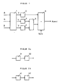
- FIG. 1 shows a basic circuit diagram of a device for coding color television signals according to the invention.
- RGB signals generated in a color television camera are present at the entrance of the device. From these, a luminance signal Y, a first color difference signal U and a second color difference signal V are generated in a matrix circuit 1.
- the luminance signal Y is fed to a three-dimensional filter circuit 2 arranged in the luminance channel, the functioning of which is explained in more detail in connection with FIG. 3.
- the three-dimensionally filtered luminance signal is fed to an input of an addition circuit 6.
- the first color difference signal U is fed to a three-dimensional filter circuit 3, the functioning of which is explained in more detail in connection with FIGS. 2a, c and d.
- the three-dimensionally filtered color difference signal U is fed to a PAL modulator 5.
- the second color difference signal V is fed to a three-dimensional filter circuit 4, the functioning of which is explained in more detail in connection with FIGS. 2b, c and d.
- the three-dimensionally filtered color difference signal V is also fed to the PAL modulator 5.
- the three-dimensionally filtered color difference signals U and V are converted into a modulated chrominance signal in a basically known manner. This is fed to a further input of the adder circuit 6, at the output of which a standardized PAL-coded color television signal is consequently available.
- FIG. 2a shows a more detailed representation of the three-dimensional sub-filter 3 from FIG. 1.
- the sub-filter 3 consists of a series connection of a horizontal low-pass filter 31 and a combined vertical-time filter 32.
- the color difference signal U is band-limited in the horizontal direction at 1.3 MHz .
- the vertically-temporal filter 32 the horizontally band-limited color difference signal is band-limited in the f y , f t plane.
- This band limitation can be achieved either by means of a planar (genuinely two-dimensional) filtering or by cascading two one-dimensional filters operating diagonally in the f y , f t plane.
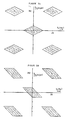
- An example of the effect of such filters is shown in FIG. 2c.
- the hatched areas correspond to the passbands.
- the band limitation mentioned can also be achieved by cascading a filter acting in a purely vertical direction with a vertical-time filter acting in the diagonal direction.
- An example of the effect of such filters is shown in FIG. 2d.
- the hatched areas also correspond to the passbands here.
- FIG. 2b shows a more detailed representation of the three-dimensional sub-filter 4 from FIG. 1.
- the sub-filter 4 consists of a series connection of a horizontal low-pass filter 41 and a combined vertical-time filter 42.
- the color difference signal V is band-limited in the horizontal direction at 1.3 MHz .
- the vertical-time filter 42 the horizontally band-limited color difference signal is in the f y , f t plane band limited.
- This band limitation can be achieved by means of filters, the basic mode of operation of which corresponds to the mode of operation of the filters shown in FIGS. 2c and 2d.
- a feature of the invention is now to select the passband of the vertical-time filter 32 for the horizontal band-limited color difference signal U smaller than the passband of the vertical-time filter 42 for the horizontal band-limited color difference signal V.
- the reason for this measure is that the human eye is much less sensitive to motion blurring with respect to the color difference signal U than for motion blurring with respect to the color difference signal V. In other words, this means that the color difference signal V is transmitted with greater resolution (or higher band width) in the time direction than the color difference signal U.
- the three-dimensional frequency space, which must be created for the color difference signal U by means of three-dimensional filtering, is thus smaller than the frequency space created for the color difference signal V. Considered clearly, this means that the hatched areas in FIGS. 2c and 2d for the U component of the color information are smaller than those for the V component.
- the luminance signal Y generated in the matrix 1 (see FIG. 1) is fed to the input of the filter shown in FIG. 3. This is initially band-limited in the horizontal direction at 6 MHz.
- the band-limited signal at 6 MHz is split into a component whose frequencies range from 0-3.6 MHz (low-pass filter 22) and a component whose frequencies range from 3.6-6.0 MHz (high-pass filter 12).
- the latter, higher-frequency components of the luminance signal are subjected to a vertical-temporal filtering, which proceeds as follows:
- the higher-frequency luminance signal components are first fed to first switching means 13, 14, 15, 16, in which they are subjected to vertical-time filtering that is inverse to the vertical-time filtering of the first color difference signal U.
- first switching means 13, 14, 15, 16 in which they are subjected to vertical-time filtering that is inverse to the vertical-time filtering of the first color difference signal U.
- any luminance components in the three-dimensional frequency space are removed from the locations which were assigned to the first color difference signal U by the three-dimensional filtering in the filter 3 (see FIG. 1).
- the higher-frequency luminance signal components are modulated in a modulator circuit 13 as well as the color difference signal U in the PAL coder 5.
- a modified carrier frequency is used for this U-modulation of the higher-frequency luminance signal components, which has the following properties: - it causes the same shifts in the f y , f t plane as the color subcarrier used in the conventional PAL coder; - It has a frequency in the f x direction which is greater than the highest horizontal frequency of the luminance component. In this way it is achieved that no alias interference occurs for horizontal frequencies.
- the higher-frequency luminance components are shifted by the modulation with the carrier frequency in such a way that the "later spectral gaps" in the luminance signal are centered around the origin.
- a filtering inverse to the three-dimensional filtering of the color difference signal U is carried out by subjecting the output signal of the modulator 13 in the vertical-time filter 14 to the same vertical-time filtering as the color difference signal U in the vertical-time filter 32 and then in an adder 15 from the output signal of Modulator 13 is subtracted.
- the output signal of the adder 15 is processed in a demodulator 16 subjected to the inverse of that of the modulator 13, and thereby brought back into the higher-frequency luminance signal range.
- the output signal of the demodulator 16 is now band-limited in the three-dimensional frequency space exactly to the spaces that are not occupied by the color difference signal U.
- the output signal of the demodulator 16 must now be subjected to a further vertical-temporal filtering in order to clear the spaces that were assigned to the second color difference signal V by its three-dimensional filtering in the filter 4.
- the output signal of the demodulator 16 is fed to second switching means 17, 18, 19, 20, in which it is subjected to vertical-time filtering which is inverse to the vertical-time filtering of the second color difference signal V.
- the output signal of the demodulator 16 is modulated in the same way as the color difference signal V in the PAL coder 5.
- the modified carrier frequency used in this modulation has the same properties as the modified carrier frequency described above.
- the output signal of the demodulator 16 is viewed in this way by modulation with the modified carrier frequency shifted that the "later spectral gaps" in the luminance signal are folded back close to the origin.
- this goal could also have been achieved if the sequence of the first (13, 14, 15, 16) and second (17, 18, 19, 20) switching means had been exchanged, ie if the clearances were the first in the luminance signal would have been created for the V component and only then the free spaces for the U component of the color information.
- the output signal of the demodulator 20 is added in an adder 21 to the delayed (delay element 23) low-frequency luminance signal component.
- the three-dimensionally filtered luminance signal is available at the output of the adder stage 21. This is fed to the adder 6 (see FIG. 1) and added there with the chrominance signal to form a standard PAL signal, which is then transmitted via the transmission channel.
- FIG. 4 shows a basic circuit diagram of a device for decoding PAL color television signals according to the invention.
- the PAL color television signal transmitted via the transmission channel is present at the input. This is fed on the one hand to a three-dimensional filter circuit 50, the functioning of which is explained in more detail in connection with FIG. 6, and on the other hand to a conventional PAL demodulator 51.
- a first output signal of the PAL demodulator 51 is fed to a three-dimensional filter circuit 52, the functioning of which is explained in more detail in connection with FIG. 5a.
- a second output signal of the PAL demodulator 51 is fed to a three-dimensional filter circuit 51, the functioning of which is explained in more detail in connection with FIG. 5b.
- FIG. 5a shows a more detailed illustration of the three-dimensional sub-filter 52 from FIG. 4.
- the sub-filter 52 consists of a series connection of a combined vertical-time filter 521 and a horizontal low-pass filter 522.
- the combined vertical-time filter 521 is constructed and dimensioned in the same way as the combined one vertical-time filter 32 on the transmission side.
- the output signal of the vertical-time filter 521 is band-limited at 0.7 MHz.
- FIG. 5b shows a more detailed illustration of the three-dimensional sub-filter 53 from FIG. 4.
- the sub-filter 53 consists of a series connection of a combined vertical-time filter 531 and a horizontal low-pass filter 532.
- the combined vertical-time filter 531 is constructed and dimensioned in the same way as the combined one vertical-time filter 42 on the transmission side.
- the output signal of the vertical-time filter 531 is band-limited at 0.7 MHz.
- the band limitation of the color difference signals in the horizontal direction described above can therefore take place at 0.7 MHz (or 700 KHz) because the resolution achieved in the horizontal direction is sufficient for the color difference signals obtained at the output of the horizontal low-pass filter 522 or 532 for the human eye.
- This band limitation at 0.7 MHz is also the prerequisite for the fact that the spectral free spaces in the luminance signal on the transmitter and receiver side need only be created for luminance signal frequencies which are above 3.6 MHz.
- FIG. 6 shows a more detailed illustration of the three-dimensional filter circuit 50 of FIG. 4.
- the input of this filter circuit is supplied with the PAL color television signal transmitted via the channel, which is band-limited at 5 MHz due to the limited bandwidth of the transmission channel in the horizontal direction.
- This signal is split into a portion whose frequencies range from 0-3.4 MHz (low-pass filter 70) and a portion whose frequencies range from 3.4-5 MHz (high-pass filter 60).
- the first or second switching means are constructed in the same way as that First or second switching means 13, 14, 15, 16 or 17, 18, 19, 20 used on the transmitter side.
- the dimensioning of the vertical-time filter on the receiving side can be varied in comparison to the vertical-time filter on the transmitter side. A loss in motion resolution caused by the transmitter filtering can thereby be compensated for again.
- the vertically-temporally filtered output signal of demodulator 68 is added in an adder 69 to the delayed (delay element 71) low-frequency luminance signal component.
- the three-dimensionally filtered luminance signal is available at the output of the adder stage 69.
- a coder is used on the transmission side, as described in one or more of claims 1-6. If a PAL color television receiver which has a conventional PAL decoder is now used at the receiving end, there is an overall reduction in cross-color and cross-luminance in comparison with transmission methods with conventional PAL coders and decoders.
- a conventional coder is used on the transmitter side and a PAL color television receiver with a decoder on the receiving side, as described in one or more or claims 7-11. Even with such a transmission method, there is an overall reduction in cross-color and cross-luminance in comparison to transmission methods with conventional PAL coders and decoders.
- a coder as described in one or more of claims 1-6 is used on the transmitter side and a decoder as described in one or more of claims 7-11 is used on the receiving side.
- this method neither cross-color nor cross-luminance interference occurs in the receiver.
- the horizontal resolution for the luminance signal is 5 MHz and is not - as in conventional systems - limited to 3.9 MHz, for example.
- FIG. 7 An example of an implementation of a combined vertical-time filter can be seen in FIG. 7. It consists essentially of 4 memory units in which the input signal is delayed by 312 lines, 5 multipliers in which the undelayed input signal with a coefficient C2, the signal delayed by 312 lines with a coefficient C1, the signal delayed by 624 lines with a coefficient C0, the signal delayed by 936 lines by a coefficient C1, and the signal delayed by 1248 lines is multiplied by a coefficient C2, and an adder in which the output signals of the 5 multipliers are added.
Landscapes
- Engineering & Computer Science (AREA)
- Multimedia (AREA)
- Signal Processing (AREA)
- Color Television Systems (AREA)
- Processing Of Color Television Signals (AREA)
Applications Claiming Priority (2)
| Application Number | Priority Date | Filing Date | Title |
|---|---|---|---|
| DE3807248 | 1988-03-05 | ||
| DE3807248A DE3807248A1 (de) | 1988-03-05 | 1988-03-05 | Einrichtung zur codierung und decodierung von farbfernsehsignalen nach dem pal-standard |
Publications (2)
| Publication Number | Publication Date |
|---|---|
| EP0331985A2 true EP0331985A2 (fr) | 1989-09-13 |
| EP0331985A3 EP0331985A3 (fr) | 1991-09-18 |
Family
ID=6348949
Family Applications (1)
| Application Number | Title | Priority Date | Filing Date |
|---|---|---|---|
| EP19890103210 Withdrawn EP0331985A3 (fr) | 1988-03-05 | 1989-02-23 | Méthode et dispositifs de codage et de décodage de signaux de télévision couleur |
Country Status (6)
| Country | Link |
|---|---|
| US (1) | US4947243A (fr) |
| EP (1) | EP0331985A3 (fr) |
| JP (1) | JPH0263297A (fr) |
| CN (1) | CN1015504B (fr) |
| AU (1) | AU628271B2 (fr) |
| DE (1) | DE3807248A1 (fr) |
Cited By (1)
| Publication number | Priority date | Publication date | Assignee | Title |
|---|---|---|---|---|
| EP0425799A3 (en) * | 1989-11-02 | 1992-11-25 | Grundig E.M.V. Elektro-Mechanische Versuchsanstalt Max Grundig Hollaend. Stiftung & Co. Kg. | Device for coding colour television signals |
Families Citing this family (7)
| Publication number | Priority date | Publication date | Assignee | Title |
|---|---|---|---|---|
| DE3912323A1 (de) * | 1989-04-14 | 1990-10-18 | Grundig Emv | Farbfernsehsystem mit einrichtung zur codierung und decodierung von farbfernsehsignalen |
| US5086340A (en) * | 1990-10-19 | 1992-02-04 | Zenith Electronics Corporation | Co-channel interference reduction system for digital high definition television |
| NL9101080A (nl) * | 1991-06-24 | 1993-01-18 | Koninkl Philips Electronics Nv | Inrichting voor het splitsen van een digitaal geinterlinieerd televisie signaal in componenten. |
| GB9214214D0 (en) * | 1992-07-03 | 1992-08-12 | Snell & Wilcox Ltd | Video signal processing |
| KR100309358B1 (ko) * | 1992-07-30 | 2001-12-28 | 요트.게.아. 롤페즈 | 역방향재생모드에서텔레비젼프레임을디스플레이하는디바이스 |
| CN100592806C (zh) * | 2006-08-15 | 2010-02-24 | 联咏科技股份有限公司 | 自适性影像处理装置与方法 |
| JP6456084B2 (ja) * | 2014-09-24 | 2019-01-23 | キヤノン株式会社 | 画像処理装置、画像処理方法及びプログラム |
Family Cites Families (4)
| Publication number | Priority date | Publication date | Assignee | Title |
|---|---|---|---|---|
| JPS6074893A (ja) * | 1983-09-30 | 1985-04-27 | Sony Corp | デイジタルカラ−デコ−ダ |
| US4683490A (en) * | 1985-06-05 | 1987-07-28 | Rca Corporation | Video signal processing apparatus |
| GB2188810B (en) * | 1986-04-02 | 1990-01-04 | Sony Corp | Encoding and decoding component digital video signals |
| GB8608811D0 (en) * | 1986-04-11 | 1986-05-14 | Avesco Plc | Video comb filter digital decoder |
-
1988
- 1988-03-05 DE DE3807248A patent/DE3807248A1/de not_active Withdrawn
-
1989
- 1989-02-23 EP EP19890103210 patent/EP0331985A3/fr not_active Withdrawn
- 1989-03-03 US US07/319,009 patent/US4947243A/en not_active Expired - Fee Related
- 1989-03-06 AU AU31023/89A patent/AU628271B2/en not_active Ceased
- 1989-03-06 JP JP1053608A patent/JPH0263297A/ja active Pending
- 1989-03-06 CN CN89102508.1A patent/CN1015504B/zh not_active Expired
Cited By (1)
| Publication number | Priority date | Publication date | Assignee | Title |
|---|---|---|---|---|
| EP0425799A3 (en) * | 1989-11-02 | 1992-11-25 | Grundig E.M.V. Elektro-Mechanische Versuchsanstalt Max Grundig Hollaend. Stiftung & Co. Kg. | Device for coding colour television signals |
Also Published As
| Publication number | Publication date |
|---|---|
| AU628271B2 (en) | 1992-09-10 |
| AU3102389A (en) | 1989-09-07 |
| EP0331985A3 (fr) | 1991-09-18 |
| JPH0263297A (ja) | 1990-03-02 |
| DE3807248A1 (de) | 1989-09-14 |
| US4947243A (en) | 1990-08-07 |
| CN1015504B (zh) | 1992-02-12 |
| CN1036871A (zh) | 1989-11-01 |
Similar Documents
| Publication | Publication Date | Title |
|---|---|---|
| DE2810697C2 (de) | Verfahren zur Trennung des Farbartsignals vom Leuchtdichtesignal bei Farbfernsehsignalen mit quadraturmodulierten Farbhilfsträgern | |
| DE3435264C2 (fr) | ||
| EP0346766A1 (fr) | Procédé pour la réduction d'artefacts d'enconbrement dans le codage de scène de vidéo par transformation en cosinus discrète avec débit de données réduit | |
| DD295480A5 (de) | Einrichtung zum ergaenzen eines fernsehsignals | |
| EP0090236A2 (fr) | Système pour la transmission numérique de signaux d'images de télévision à redondance réduite | |
| WO1990013210A1 (fr) | Systeme de television couleur comportant des dispositifs pour le codage et le decodage de signaux de television couleur | |
| EP0146694B1 (fr) | Méthode d'augmentation compatible de la définition pour un système de transmission en télévision | |
| DE3786581T2 (de) | Kodierung und dekodierung von digitalen videokomponentensignalen. | |
| DE68925642T2 (de) | System zur zusammensetzung und trennung von komponenten eines videosignals | |
| DE3234938A1 (de) | Trennfilter | |
| DE2837120A1 (de) | Verfahren und anordnung zur verarbeitung von pal-farbfernsehsignalen in digitaler form | |
| DE3203852C2 (de) | Anordnung zur digitalen Filterung von digitalisierten Chrominanzsignalen in einem Digitalkomponenten-Fernsehsystem | |
| EP0331985A2 (fr) | Méthode et dispositifs de codage et de décodage de signaux de télévision couleur | |
| DE3249132T1 (de) | Farbtraegersignal-trennschaltung | |
| DE69019696T2 (de) | Verfahren und Apparat zur Verminderung von Rauschimpulsen in digitalen Fernsehempfängern. | |
| DE69025280T2 (de) | Verfahren und Vorrichtung zur digitalen Videosignalverarbeitung | |
| DE4134536C2 (de) | Verfahren und Vorrichtung zum Aufzeichnen von Videosignalen | |
| EP0425799B1 (fr) | Dispositif de codage de signaux de télévision couleur | |
| DE69030889T2 (de) | Abtastfrequenzabwärtswandler | |
| DE3633716C2 (fr) | ||
| DE1813954B1 (de) | System zur Trennung eines PAL-Farbbildsignals in Leuchtdichte- und Farbartsignal | |
| DE3901117C1 (en) | Compatible frequency-division multiplex television system | |
| DE3825936C2 (de) | Einrichtung und Verfahren zur Codierung eines komponentenunterteilten digitalen Videosignals | |
| DE69028400T2 (de) | Ausgedehntes zusammengesetztes Fernsehsystem | |
| DE3107736C2 (fr) |
Legal Events
| Date | Code | Title | Description |
|---|---|---|---|
| PUAI | Public reference made under article 153(3) epc to a published international application that has entered the european phase |
Free format text: ORIGINAL CODE: 0009012 |
|
| AK | Designated contracting states |
Kind code of ref document: A2 Designated state(s): AT DE FR GB IT |
|
| PUAL | Search report despatched |
Free format text: ORIGINAL CODE: 0009013 |
|
| AK | Designated contracting states |
Kind code of ref document: A3 Designated state(s): AT DE FR GB IT |
|
| STAA | Information on the status of an ep patent application or granted ep patent |
Free format text: STATUS: THE APPLICATION IS DEEMED TO BE WITHDRAWN |
|
| 18D | Application deemed to be withdrawn |
Effective date: 19920319 |