EP0331962A1 - Anlage zum Ausrichten eines Leistungsstrahls - Google Patents
Anlage zum Ausrichten eines Leistungsstrahls Download PDFInfo
- Publication number
- EP0331962A1 EP0331962A1 EP89102934A EP89102934A EP0331962A1 EP 0331962 A1 EP0331962 A1 EP 0331962A1 EP 89102934 A EP89102934 A EP 89102934A EP 89102934 A EP89102934 A EP 89102934A EP 0331962 A1 EP0331962 A1 EP 0331962A1
- Authority
- EP
- European Patent Office
- Prior art keywords
- receiver
- transmitter
- auxiliary
- main
- axis
- Prior art date
- Legal status (The legal status is an assumption and is not a legal conclusion. Google has not performed a legal analysis and makes no representation as to the accuracy of the status listed.)
- Ceased
Links
Images
Classifications
-
- G—PHYSICS
- G02—OPTICS
- G02B—OPTICAL ELEMENTS, SYSTEMS OR APPARATUS
- G02B6/00—Light guides; Structural details of arrangements comprising light guides and other optical elements, e.g. couplings
-
- B—PERFORMING OPERATIONS; TRANSPORTING
- B23—MACHINE TOOLS; METAL-WORKING NOT OTHERWISE PROVIDED FOR
- B23K—SOLDERING OR UNSOLDERING; WELDING; CLADDING OR PLATING BY SOLDERING OR WELDING; CUTTING BY APPLYING HEAT LOCALLY, e.g. FLAME CUTTING; WORKING BY LASER BEAM
- B23K26/00—Working by laser beam, e.g. welding, cutting or boring
- B23K26/02—Positioning or observing the workpiece, e.g. with respect to the point of impact; Aligning, aiming or focusing the laser beam
- B23K26/04—Automatically aligning, aiming or focusing the laser beam, e.g. using the back-scattered light
- B23K26/042—Automatically aligning the laser beam
- B23K26/043—Automatically aligning the laser beam along the beam path, i.e. alignment of laser beam axis relative to laser beam apparatus
Definitions
- the present invention relates to the alignment of an optical beam, for example of a power infrared laser beam used for a welding operation.
- Such alignment consists, from an input beam which is supplied by a power source with an imposed position and direction, to obtain an output beam whose position and direction can be adjusted to allow its use effective.
- the journey to be made is divided into three sections so as to obtain two intermediate points in view of one another, located inside the water box.
- devices which will be called hereafter respectively transmitter and receiver.
- the source-emitter and receiver-welding head paths are traversed according to known arrangements, this latter path being along the axis of the tube to be repaired and can be defined relative to the receiver by pressing the latter on a surface integral with this tube.
- the system includes - a transmitter for receiving main power radiation and for transmitting it in the form of a main connecting beam, the latter being controllable in direction so that it can be directed towards a mobile receiver, said receiver, this receiver being capable, when it usefully receives this main connection beam, of transmitting it in the form of a main output beam by showing a controllable angular deviation between these two beams, a mobile carrier carrying this receiver and controllable in position to control the position of this main output beam, positioning means controlling the position of this carrier to bring said receiver to an axis of use on which the power of said main output beam is to be used, - And optical orientation means comprising: an auxiliary source for generating auxiliary radiation transmitted by said emitter in the form of an auxiliary link beam in the same direction as said main link beam, -
- the object of the present invention is in particular to produce a simple and precise system which can be used continuously during successive welding or other processing operations using a power beam. It also aims to achieve such a system with a minimum number of fragile devices associated with the receiver which moves, according to the example given, in the water box.
- Systems according to the present invention include - a transmitter for receiving at least one input beam and for transmitting it in the form of a link beam, - a mobile receiver remote from said transmitter, - And control means so that this receiver receives this link beam and transforms it into an output beam aligned on an axis of use.
- a system comprises: said transmitter for receiving a main input beam consisting of a main radiation to be used and for transmitting it in the form of a main link beam controllable in direction, said receiver for receiving this main connection beam, and for applying to it a controllable angular deflection capable of transforming it into a main output beam aligned on an axis of use linked to a structure external to said alignment system, - And optical orientation means comprising: - an auxiliary source for generating auxiliary radiation in the form of an auxiliary input beam aligned on the path of said main input beam so that this auxiliary input beam is transformed by said emitter into an auxiliary connecting beam aligned with the path of said main connecting beam, and this auxiliary linking beam is transformed by said receiver into an auxiliary output beam aligned with the path of said main output beam, transmitter control means sensitive to a fraction of the radiation of said auxiliary link beam received by said receiver in order to control said transmitter so that said auxiliary and main link beams are directed towards this
- said transmitter and receiver control means include: means for returning the light from said auxiliary connection beam to said transmitter, - And an annular separator which surrounds said main input beam, and which directs the light returned by said return means towards detection and analysis means.
- a system comprises - said transmitter for receiving at least one input beam and for transmitting it in the form of a link beam controllable in direction, - said receiver, - and transmitter control means sensitive to the irradiation of said receiver by said link beam to enable said transmitter to be controlled so that it directs this beam to this receiver, - Said alignment system being characterized in that said transmitter control means comprise an assembly retroreflector linked to said receiver and consisting of several retroreflectors each returning a corresponding part of said connecting beam in the same direction of this linking beam to constitute a retroreflected beam, - And a retroreflective beam detector linked to said transmitter and forming an image of said retroreflective assembly on an image analysis system making it possible to detect the position of said receiver with respect to said connecting beam.
- This image analysis system thus constitutes a position detector.
- said image analysis system makes it possible to compare the light fluxes received in various image elements which are formed respectively by the various so-called retroreflectors and which form part of said image of said retroreflector assembly.
- said retroreflectors are at least three in number and are angularly distributed around the periphery of said connecting bundle (PL).
- said retroreflectors leave angular intervals between them for a light usable by other said control means.
- a system comprises: - said transmitter, said receiver receiving this link beam and applying to it a controllable angular deviation to transform it into said output beam, - And receiver control means to allow to control said controllable deflection so as to align said connecting beam on an axis of use linked to a structure external to said alignment system, these receiver control means themselves comprising : a receiver mirror linked to said receiver for returning part of the light from said link beam to said transmitter in the form of a return beam, the direction of which is affected by said controllable deflection, - and a deviation detector linked to said transmitter and sensitive to deviations of this return beam, - Said alignment system being characterized in that said receiver mirror is placed in the path of said output beam so that said return beam is formed from this output beam and passes through said receiver in return, this mirror having an axis perpendicular to its surface and being mounted to orient itself with respect to said external structure so as to align its axis with said axis of use.
- said receiver mirror is carried at a distance from said receiver by an outlet part linked to the latter, this outlet part being provided with orientation means which are supported on said external structure to orient said receiver mirror with respect to said axis of use.
- This mirror is an annular sticker mirror.
- the system according to the invention comprises a common computer supplied by the two so-called position and deviation detectors.
- a grouping of electronic elements constituted by this computer and these two detectors reduces the size and fragility of the system.
- the present invention also relates to a method of radiation treatment, in particular welding, inside parts of difficult access, in particular tubes in a nuclear power station, this method comprising the following operations, - a treatment head is introduced into a room to be treated, - a radiation treatment is generated at a distance from this part, - and a beam of this radiation is aligned along an axis of use linked to this part to supply this treatment head, -
- This method being characterized by the fact that this beam is aligned using an alignment system as described above according to at least one aspect of the invention.
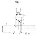
- a carbon dioxide power laser 1 emits an infrared power beam 2 constituting a main radiation.
- an annular mirror 3 On the axis of this beam is arranged an annular mirror 3, whose plane makes an angle of 45 ° and whose center coincides with the axis of the beam.
- a He Ne 4 laser emits a beam of visible auxiliary radiation 5.
- This beam is enlarged at 5A and then sent to a separator 5B which is opaque in its central part.
- a visible tubular beam 6 is thus obtained, the internal diameter of which corresponds substantially to the external diameter of the power beam.
- This beam is sent to the annular mirror 3 and thus becomes said auxiliary input beam AE which is coaxial with said main input beam PE constituted by the beam 2.
- a fine mechanical adjustment of the position of the mirror 3 allows perfect alignment the two beams using an auxiliary target when installing the lasers near the workplace.
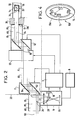
- FIG. 2 represents the means used for transporting the main beam to said processing head 30.
- the latter is a welding head. It comprises an envelope 32, a focusing lens 34 and a 45-degree mirror 36. It has been introduced into a tube to be treated 14 in which a cuff must be welded and whose axis 24 constitutes said axis of use.
- This tube is located inside the water box 20 of a steam generator (not shown) comprising, as known, many other tubes in which it may be necessary to also carry out welding treatments.
- the beam transport means consist of two optical beam deflection assemblies. These two assemblies constitute said transmitter 11 and said receiver 12. They are motorized so as to each provide a deviation which is shown as zero in Figure 2, but which is controlled according to two angular coordinates.
- the receiver 12 is mounted on a carrier 22 which is also motorized so that its position is controlled according to one, two or three position coordinates, that is to say that the position of the receiver 12 is also controlled. It is so as to center an output window of this receiver on the axis of use.
- the direction of the beams entering the transmitter 11 is imposed (that of the axis of the laser 1, with respect to which the transmitter 11 is adjusted when the system is mounted), as is that of the beams leaving the receiver 12 (it is that of the axis of the tube to be treated 14, the receiver being guided relative to this tube by means of a tube 13 secured to this receiver and coming to bear against a not shown tubular plate secured to this tube).
- the control of the angular deviations of the transmitter and the receiver therefore makes it possible to direct the output beams from the transmitter to the receiver and to ensure that the input beams capable of being usefully received by the receiver come from the direction of the transmitter, so as to ensure an optical link between the transmitter and the receiver.
- This link is produced by said main PL and auxiliary link beams AL resulting from the deflection of the input beams PE and AE by the transmitter 11.
- the components of the alignment system are grouped into two sets:
- a fixed assembly is located near the manhole giving access to the water box 20. It includes on the outside of this box: - the power laser 1, - the auxiliary laser 4, the device 5A, 5B, 3 used for the mutual alignment of the beams of these two lasers, - a computer 7, - a video control unit 8, - a tube 10 entering the water box 20.
- the fixed assembly comprises, at the end of the tube 10, the motorized optical assembly constituting the emitter 11.
- the alignment system further comprises an assembly on board a carrier 22 installed in the water box 20.
- This assembly is mobile while being hung under the tubular plate. He understands : a motorized optical assembly constituting the receiver 12, - said connecting tube 13 - a sleeving tool 38 comprising the welding head 30.
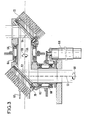
- the auxiliary connection beam AL is partially retroreflected to the transmitter 11 by four retroreflectors 15 fixed on a support 15A (see fig.4), itself fixed on the receiver opposite the transmitter.
- These retro-reflectors have the well-known shape of cube corners and have the property of returning the light in the direction from which it comes regardless of their orientation. They constitute a retroreflective assembly 15B.
- the beam retroreflected by the assembly 15B is sent through the emitter 11 to an annular separator 26 which reflects it, through a lens 27, onto another separator 28 constituted by a semi-transparent mirror.
- the light which has passed through the separator 28 forms light spots which constitute an image of the retroreflective assembly 15 in a camera 16.
- This image comprises four spots which respectively receive the light fluxes from the four elementary beams returned by the four retroreflectors, and which each constitute an image element corresponding to one of these retroreflectors.
- the camera 16 makes it possible in particular to compare the light fluxes in these four image elements. With the help of this lens, this camera constitutes said position detector. It has complex image analysis functions and constitutes a position analysis system. From the results of this analysis, by action on the emitter's motors, we perfectly adjust management to ensure its impact on the receiver. In addition, by enslaving the control of the transmitter motors on the analysis of the image received back on the camera 16, the receiver can be continuously followed by the incident beam.
- the non-reflected part of the auxiliary radiation passes through the receiver 12 to form an auxiliary output beam AS around the main output beam PS.
- This auxiliary beam arrives on a self-annealing annular receiver mirror 17 carried by the tube 13 and situated at the inlet of the tube to be treated 14.
- the tube 13 constitutes said outlet part of the receiver. It comprises an annular shoulder 13A which is supported by means of the tool 38, on the not shown tubular plate to which the tube 14 is linked. This thus ensures the coincidence of the axis of the receiver mirror 17 with the axis of the tube to be treated 14.
- the radiation returned by this receiver mirror constitutes said return beam. It crosses the receiver 12 and the transmitter 11, is reflected on the separator 26 and, through the lens 27, on the separator 28 to arrive at a camera 18 which constitutes said deviation detector and which is located, like camera 16, in the housing 9.
- the image formed by this radiation on this camera 18 is analyzed by the latter which provides signals representative of two coordinates of the angular difference of the auxiliary output beam AS, and therefore also of the main output beam PS , relative to the axis of use 24.
- the axis of the output beams is adjusted so that it is aligned with the axis 24 of the tube 14 which is the same as that of the mirror 17.
- each motorized optical assembly such that the emitter 11 or the receiver 12 receives a composite beam constituted by the main radiation surrounded by the auxiliary radiation with a common axis which is deflected at each reflection.
- This assembly for example the transmitter 11, comprises the following elements: - Two flat mirrors 52 and 54 inclined at 45 degrees on the axes 53 and 55 of the beams they receive and rotating around this axis which allows to sweep all the space around this set as represented by the arrows 58 and 59 .
- - Bearings 60, 62, 64 and 66 to allow and guide these rotations.
- - And radiators 70 and 72 to carry the mirrors 52 and 54 and to cool them when they are subjected to the main radiation.
- a welding operation using the system described above is done as follows, after an initial installation of the two so-called fixed and on-board assemblies.
- a first operation is done by calculation because we know the coordinates of the initial position of the on-board assembly.
- This assembly is placed in a suitable position, by controlling the motors of the carrier 22, with the use of said mechanical guide means (not shown) to properly orient the receiver 12 relative to the tube to be treated 14.
- the welding head 30 is also put in place in this tube by known means unrelated to the present invention.
- the transmitter-receiver link is provided by the commands described above. Initially only the auxiliary radiation is used.
- the power laser 1 is put into operation.
- An advantage of this system is that the two radiations can be used simultaneously or separately.
- the visible auxiliary radiation is only used for the initial presetting and during transfers of the receiver and the welding head from one tube to another.
- visible radiation allows permanent control of the alignment and continuity by returning the image of any obstacle occurring on the path of the beams.
- Another advantage is that the beams can be checked up to the receiver mirror 17 located downstream of the receiver and which can be placed very close to the treatment head, in the example the welding head.
Applications Claiming Priority (2)
| Application Number | Priority Date | Filing Date | Title |
|---|---|---|---|
| FR8802473A FR2627874B1 (fr) | 1988-02-29 | 1988-02-29 | Systeme d'alignement d'un faisceau de puissance |
| FR8802473 | 1988-02-29 |
Publications (1)
| Publication Number | Publication Date |
|---|---|
| EP0331962A1 true EP0331962A1 (de) | 1989-09-13 |
Family
ID=9363730
Family Applications (1)
| Application Number | Title | Priority Date | Filing Date |
|---|---|---|---|
| EP89102934A Ceased EP0331962A1 (de) | 1988-02-29 | 1989-02-20 | Anlage zum Ausrichten eines Leistungsstrahls |
Country Status (10)
| Country | Link |
|---|---|
| US (1) | US5085509A (de) |
| EP (1) | EP0331962A1 (de) |
| JP (1) | JPH01258888A (de) |
| KR (1) | KR890013493A (de) |
| CN (1) | CN1035567A (de) |
| CA (1) | CA1316990C (de) |
| DK (1) | DK91489A (de) |
| FR (1) | FR2627874B1 (de) |
| SU (1) | SU1713425A3 (de) |
| ZA (1) | ZA891536B (de) |
Cited By (3)
| Publication number | Priority date | Publication date | Assignee | Title |
|---|---|---|---|---|
| FR2679809A1 (fr) * | 1991-08-01 | 1993-02-05 | France Etat Armement | Dispositif d'observation d'une zone d'interaction entre un faisceau laser et de la matiere et dispositif et procede de traitement par faisceau laser utilisant ce dispositif d'observation. |
| WO2018087256A1 (de) * | 2016-11-11 | 2018-05-17 | Trumpf Laser- Und Systemtechnik Gmbh | Verfahren zum bestimmen eines strahlprofils eines laserstrahls und bearbeitungsmaschine |
| WO2018086996A1 (de) * | 2016-11-11 | 2018-05-17 | Trumpf Laser- Und Systemtechnik Gmbh | Verfahren zum kalibrieren einer scannereinrichtung und bearbeitungsmaschine |
Families Citing this family (12)
| Publication number | Priority date | Publication date | Assignee | Title |
|---|---|---|---|---|
| JP2559285B2 (ja) * | 1990-03-29 | 1996-12-04 | 株式会社イセキ開発工機 | シールド型トンネル掘削機 |
| US5386221A (en) * | 1992-11-02 | 1995-01-31 | Etec Systems, Inc. | Laser pattern generation apparatus |
| US5430270A (en) * | 1993-02-17 | 1995-07-04 | Electric Power Research Institute, Inc. | Method and apparatus for repairing damaged tubes |
| US5461472A (en) * | 1993-06-28 | 1995-10-24 | At&T Ipm Corp. | Method and apparatus for measuring the parallelism of two surfaces |
| US5642297A (en) * | 1994-12-12 | 1997-06-24 | Gurley Precision Instruments, Inc. | Apparatus and method for measuring the kinematic accuracy in machines and mechanisms using absolute encoders |
| JP3560135B2 (ja) * | 1999-03-23 | 2004-09-02 | 日産自動車株式会社 | Yagレーザ溶接部の品質モニタリング方法 |
| US7279721B2 (en) | 2005-04-13 | 2007-10-09 | Applied Materials, Inc. | Dual wavelength thermal flux laser anneal |
| CN101164111B (zh) * | 2005-04-19 | 2010-06-16 | 皇家飞利浦电子股份有限公司 | 用于把辐射导向层的装置、具有这种装置的设备以及使用这种设备的方法 |
| JP6512673B2 (ja) * | 2015-03-27 | 2019-05-15 | オリンパス株式会社 | 偏心測定装置及び偏心測定方法 |
| DE102015016274B4 (de) * | 2015-12-16 | 2023-10-19 | Mbda Deutschland Gmbh | Optisches System und Verfahren zum Justieren eines Signalstrahls |
| DE102018205403A1 (de) * | 2018-04-11 | 2019-10-17 | Trumpf Laser- Und Systemtechnik Gmbh | Verfahren zum Kalibrieren einer Bearbeitungsmaschine und Bearbeitungsmaschine |
| US10989528B2 (en) * | 2019-08-27 | 2021-04-27 | Raytheon Company | High speed beam component-resolved profile and position sensitive detector |
Citations (3)
| Publication number | Priority date | Publication date | Assignee | Title |
|---|---|---|---|---|
| EP0154866A1 (de) * | 1984-02-24 | 1985-09-18 | Firma Carl Zeiss | Einrichtung zur Kompensation der Auswanderung eines Laserstrahls |
| EP0217077A2 (de) * | 1985-08-23 | 1987-04-08 | Firma Carl Zeiss | Einrichtung zur Lagekorrektur eines über eine Gelenkoptik geführten Laserstrahls |
| EP0238171A1 (de) * | 1986-01-23 | 1987-09-23 | Westinghouse Electric Corporation | Laserschweisskopf zum Verschweissen einer Muffe mit einem Rohr |
Family Cites Families (8)
| Publication number | Priority date | Publication date | Assignee | Title |
|---|---|---|---|---|
| US3844660A (en) * | 1972-11-16 | 1974-10-29 | Zygo Corp | Method and apparatus for aligning an interferometer mirror |
| US3892488A (en) * | 1974-02-22 | 1975-07-01 | Us Air Force | Laser site marking system |
| JPS57137092A (en) * | 1981-02-16 | 1982-08-24 | Olympus Optical Co Ltd | Visible guide beam projector for invisible laser device |
| US4466739A (en) * | 1982-02-26 | 1984-08-21 | Kasner William H | Laser beam alignment system |
| FR2541468B1 (fr) * | 1983-02-17 | 1986-07-11 | Commissariat Energie Atomique | Dispositif d'alignement d'un faisceau laser par l'intermediaire de moyens optiques de visee, procede de reperage de l'axe d'emission du faisceau laser et procede de mise en oeuvre du dispositif, pour controler l'alignement |
| JPS6047482A (ja) * | 1983-08-26 | 1985-03-14 | Toshiba Corp | レ−ザ照射装置 |
| DE3406676A1 (de) * | 1984-02-24 | 1985-09-05 | Fa. Carl Zeiss, 7920 Heidenheim | Einrichtung zur lagekorrektur eines ueber eine gelenkoptik gefuehrten laserstrahls |
| US4772122A (en) * | 1986-08-18 | 1988-09-20 | Westinghouse Electric Corp. | Alignment technique for laser beam optics |
-
1988
- 1988-02-29 FR FR8802473A patent/FR2627874B1/fr not_active Expired - Fee Related
-
1989
- 1989-02-20 EP EP89102934A patent/EP0331962A1/de not_active Ceased
- 1989-02-27 SU SU894613625A patent/SU1713425A3/ru active
- 1989-02-27 DK DK091489A patent/DK91489A/da not_active Application Discontinuation
- 1989-02-28 KR KR1019890002416A patent/KR890013493A/ko not_active Application Discontinuation
- 1989-02-28 ZA ZA891536A patent/ZA891536B/xx unknown
- 1989-02-28 JP JP1045564A patent/JPH01258888A/ja active Pending
- 1989-02-28 CA CA000592296A patent/CA1316990C/fr not_active Expired - Fee Related
- 1989-02-28 CN CN89100937A patent/CN1035567A/zh active Pending
- 1989-02-28 US US07/316,749 patent/US5085509A/en not_active Expired - Fee Related
Patent Citations (3)
| Publication number | Priority date | Publication date | Assignee | Title |
|---|---|---|---|---|
| EP0154866A1 (de) * | 1984-02-24 | 1985-09-18 | Firma Carl Zeiss | Einrichtung zur Kompensation der Auswanderung eines Laserstrahls |
| EP0217077A2 (de) * | 1985-08-23 | 1987-04-08 | Firma Carl Zeiss | Einrichtung zur Lagekorrektur eines über eine Gelenkoptik geführten Laserstrahls |
| EP0238171A1 (de) * | 1986-01-23 | 1987-09-23 | Westinghouse Electric Corporation | Laserschweisskopf zum Verschweissen einer Muffe mit einem Rohr |
Non-Patent Citations (2)
| Title |
|---|
| PATENT ABSTRACTS OF JAPAN vol. 6, no. 236 (M-173)(1114) 25 novembre 1982, & JP-A-57 137092 (OLYMPUS KOGAKU KOGYO K.K.) 24 août 1982, * |
| PATENT ABSTRACTS OF JAPAN vol. 9, no. 178 (E-330)(1901) 23 juillet 1985, & JP-A-60 047482 (TOSHIBA K.K.) 14 mars 1985, * |
Cited By (8)
| Publication number | Priority date | Publication date | Assignee | Title |
|---|---|---|---|---|
| FR2679809A1 (fr) * | 1991-08-01 | 1993-02-05 | France Etat Armement | Dispositif d'observation d'une zone d'interaction entre un faisceau laser et de la matiere et dispositif et procede de traitement par faisceau laser utilisant ce dispositif d'observation. |
| WO2018087256A1 (de) * | 2016-11-11 | 2018-05-17 | Trumpf Laser- Und Systemtechnik Gmbh | Verfahren zum bestimmen eines strahlprofils eines laserstrahls und bearbeitungsmaschine |
| WO2018086996A1 (de) * | 2016-11-11 | 2018-05-17 | Trumpf Laser- Und Systemtechnik Gmbh | Verfahren zum kalibrieren einer scannereinrichtung und bearbeitungsmaschine |
| CN109937100A (zh) * | 2016-11-11 | 2019-06-25 | 通快激光与系统工程有限公司 | 用于校准扫描装置的方法和加工机 |
| US10739191B2 (en) | 2016-11-11 | 2020-08-11 | Trumpf Laser- Und Systemtechnik Gmbh | Determining a beam profile of a laser beam |
| CN109937100B (zh) * | 2016-11-11 | 2022-03-01 | 通快激光与系统工程有限公司 | 用于校准扫描装置的方法和加工机 |
| CN114192970A (zh) * | 2016-11-11 | 2022-03-18 | 通快激光与系统工程有限公司 | 用于校准扫描装置的方法和加工机 |
| US11899421B2 (en) | 2016-11-11 | 2024-02-13 | Trumpf Laser- Und Systemtechnik Gmbh | Calibrating a scanner device |
Also Published As
| Publication number | Publication date |
|---|---|
| FR2627874A1 (fr) | 1989-09-01 |
| JPH01258888A (ja) | 1989-10-16 |
| KR890013493A (ko) | 1989-09-23 |
| US5085509A (en) | 1992-02-04 |
| CA1316990C (fr) | 1993-04-27 |
| SU1713425A3 (ru) | 1992-02-15 |
| DK91489A (da) | 1989-08-30 |
| ZA891536B (en) | 1989-11-29 |
| CN1035567A (zh) | 1989-09-13 |
| DK91489D0 (da) | 1989-02-27 |
| FR2627874B1 (fr) | 1995-06-16 |
Similar Documents
| Publication | Publication Date | Title |
|---|---|---|
| EP0331962A1 (de) | Anlage zum Ausrichten eines Leistungsstrahls | |
| EP0419320B1 (de) | Vorrichtung zur automatischen Harmonisierung für ein opto-elektronisches System | |
| FR2599139A1 (fr) | Appareil d'assistance a l'alignement axial pour les operations de commande a distance et procede connexe | |
| EP0898726B1 (de) | Diffraktive optik mit synthetischer apertur und laserschneidvorrichtung mit einer solchen optik | |
| FR2581768A1 (fr) | Composant optoelectrique bidirectionnel formant coupleur optique | |
| EP0712009A1 (de) | Integriertes Winkelabweichungs-Messsystem | |
| FR2669427A1 (fr) | Dispositif de controle d'alignement de deux voies optiques et systeme de designation laser equipe d'un tel dispositif de controle. | |
| FR2659752A1 (fr) | Systemes optiques de formation d'image. | |
| EP0995145B1 (de) | Beugungsoptik mit zusammengesetzter apertur und veränderlicher brennweite und laserschneidevorrichtung mit dieser optik | |
| CA2187339C (en) | Radiation beam position sensor | |
| FR2606167A1 (fr) | Appareil optique compact pour suivre la course d'un outil le long d'une ligne de deplacement sur une piece a usiner | |
| EP0702246B1 (de) | Tragbares Gerät zum Messen der Rückstreuung von Licht | |
| FR2861851A1 (fr) | Dispositif de detection optique d'un objet distant | |
| CA2308864A1 (fr) | Procede et dispositif pour detecter les erreurs d'harmonisation de l'axe d'un instrument optique | |
| EP0509933B1 (de) | Verfahren zur Ausrichtung eines Laserstrahles auf die Oeffnung einer Düse und Fokussierkopf zur Laserstrahlbearbeitung | |
| EP0321048A1 (de) | Hochleistungslichtquelle für Kameras | |
| US8792099B1 (en) | Method and apparatus for phase detection in a beam steering laser array | |
| EP1045588A1 (de) | Vorrichtung zur Übertragung von digitalen Videobildern | |
| FR2576114A1 (fr) | Analyseur optico-mecanique ayant un champ de telemetrie fixe | |
| EP0038297A1 (de) | Verfahren zum Entgräten eines scharfen Instruments, Ausführung des Verfahrens und durch dieses Verfahren erhaltenes scharfes Instrument | |
| FR2690584A1 (fr) | Dispositif d'acquisition de données et système de communication comportant un tel dispositif. | |
| EP2232308B1 (de) | Bildgebendes lasersystem | |
| EP0545788B1 (de) | Verfahren und Anordnung zur Positionierung eines Werkzeugs gegenüber der Achse einer Rohr | |
| EP0057626A2 (de) | Leuchtendes Zielobjekt für die optische dreidimensionale Messtechnik und Messverfahren | |
| EP0165116B1 (de) | Anordnung zur optischen Detektion von Weitem |
Legal Events
| Date | Code | Title | Description |
|---|---|---|---|
| PUAI | Public reference made under article 153(3) epc to a published international application that has entered the european phase |
Free format text: ORIGINAL CODE: 0009012 |
|
| AK | Designated contracting states |
Kind code of ref document: A1 Designated state(s): BE CH DE ES GB IT LI NL SE |
|
| 17P | Request for examination filed |
Effective date: 19900305 |
|
| 17Q | First examination report despatched |
Effective date: 19910705 |
|
| STAA | Information on the status of an ep patent application or granted ep patent |
Free format text: STATUS: THE APPLICATION HAS BEEN REFUSED |
|
| 18R | Application refused |
Effective date: 19951216 |