EP0331962A1 - Power beam alignment system - Google Patents
Power beam alignment system Download PDFInfo
- Publication number
- EP0331962A1 EP0331962A1 EP89102934A EP89102934A EP0331962A1 EP 0331962 A1 EP0331962 A1 EP 0331962A1 EP 89102934 A EP89102934 A EP 89102934A EP 89102934 A EP89102934 A EP 89102934A EP 0331962 A1 EP0331962 A1 EP 0331962A1
- Authority
- EP
- European Patent Office
- Prior art keywords
- receiver
- transmitter
- auxiliary
- main
- axis
- Prior art date
- Legal status (The legal status is an assumption and is not a legal conclusion. Google has not performed a legal analysis and makes no representation as to the accuracy of the status listed.)
- Ceased
Links
Images
Classifications
-
- G—PHYSICS
- G02—OPTICS
- G02B—OPTICAL ELEMENTS, SYSTEMS OR APPARATUS
- G02B6/00—Light guides; Structural details of arrangements comprising light guides and other optical elements, e.g. couplings
-
- B—PERFORMING OPERATIONS; TRANSPORTING
- B23—MACHINE TOOLS; METAL-WORKING NOT OTHERWISE PROVIDED FOR
- B23K—SOLDERING OR UNSOLDERING; WELDING; CLADDING OR PLATING BY SOLDERING OR WELDING; CUTTING BY APPLYING HEAT LOCALLY, e.g. FLAME CUTTING; WORKING BY LASER BEAM
- B23K26/00—Working by laser beam, e.g. welding, cutting or boring
- B23K26/02—Positioning or observing the workpiece, e.g. with respect to the point of impact; Aligning, aiming or focusing the laser beam
- B23K26/04—Automatically aligning, aiming or focusing the laser beam, e.g. using the back-scattered light
- B23K26/042—Automatically aligning the laser beam
- B23K26/043—Automatically aligning the laser beam along the beam path, i.e. alignment of laser beam axis relative to laser beam apparatus
Definitions
- the present invention relates to the alignment of an optical beam, for example of a power infrared laser beam used for a welding operation.
- Such alignment consists, from an input beam which is supplied by a power source with an imposed position and direction, to obtain an output beam whose position and direction can be adjusted to allow its use effective.
- the journey to be made is divided into three sections so as to obtain two intermediate points in view of one another, located inside the water box.
- devices which will be called hereafter respectively transmitter and receiver.
- the source-emitter and receiver-welding head paths are traversed according to known arrangements, this latter path being along the axis of the tube to be repaired and can be defined relative to the receiver by pressing the latter on a surface integral with this tube.
- the system includes - a transmitter for receiving main power radiation and for transmitting it in the form of a main connecting beam, the latter being controllable in direction so that it can be directed towards a mobile receiver, said receiver, this receiver being capable, when it usefully receives this main connection beam, of transmitting it in the form of a main output beam by showing a controllable angular deviation between these two beams, a mobile carrier carrying this receiver and controllable in position to control the position of this main output beam, positioning means controlling the position of this carrier to bring said receiver to an axis of use on which the power of said main output beam is to be used, - And optical orientation means comprising: an auxiliary source for generating auxiliary radiation transmitted by said emitter in the form of an auxiliary link beam in the same direction as said main link beam, -
- the object of the present invention is in particular to produce a simple and precise system which can be used continuously during successive welding or other processing operations using a power beam. It also aims to achieve such a system with a minimum number of fragile devices associated with the receiver which moves, according to the example given, in the water box.
- Systems according to the present invention include - a transmitter for receiving at least one input beam and for transmitting it in the form of a link beam, - a mobile receiver remote from said transmitter, - And control means so that this receiver receives this link beam and transforms it into an output beam aligned on an axis of use.
- a system comprises: said transmitter for receiving a main input beam consisting of a main radiation to be used and for transmitting it in the form of a main link beam controllable in direction, said receiver for receiving this main connection beam, and for applying to it a controllable angular deflection capable of transforming it into a main output beam aligned on an axis of use linked to a structure external to said alignment system, - And optical orientation means comprising: - an auxiliary source for generating auxiliary radiation in the form of an auxiliary input beam aligned on the path of said main input beam so that this auxiliary input beam is transformed by said emitter into an auxiliary connecting beam aligned with the path of said main connecting beam, and this auxiliary linking beam is transformed by said receiver into an auxiliary output beam aligned with the path of said main output beam, transmitter control means sensitive to a fraction of the radiation of said auxiliary link beam received by said receiver in order to control said transmitter so that said auxiliary and main link beams are directed towards this
- said transmitter and receiver control means include: means for returning the light from said auxiliary connection beam to said transmitter, - And an annular separator which surrounds said main input beam, and which directs the light returned by said return means towards detection and analysis means.
- a system comprises - said transmitter for receiving at least one input beam and for transmitting it in the form of a link beam controllable in direction, - said receiver, - and transmitter control means sensitive to the irradiation of said receiver by said link beam to enable said transmitter to be controlled so that it directs this beam to this receiver, - Said alignment system being characterized in that said transmitter control means comprise an assembly retroreflector linked to said receiver and consisting of several retroreflectors each returning a corresponding part of said connecting beam in the same direction of this linking beam to constitute a retroreflected beam, - And a retroreflective beam detector linked to said transmitter and forming an image of said retroreflective assembly on an image analysis system making it possible to detect the position of said receiver with respect to said connecting beam.
- This image analysis system thus constitutes a position detector.
- said image analysis system makes it possible to compare the light fluxes received in various image elements which are formed respectively by the various so-called retroreflectors and which form part of said image of said retroreflector assembly.
- said retroreflectors are at least three in number and are angularly distributed around the periphery of said connecting bundle (PL).
- said retroreflectors leave angular intervals between them for a light usable by other said control means.
- a system comprises: - said transmitter, said receiver receiving this link beam and applying to it a controllable angular deviation to transform it into said output beam, - And receiver control means to allow to control said controllable deflection so as to align said connecting beam on an axis of use linked to a structure external to said alignment system, these receiver control means themselves comprising : a receiver mirror linked to said receiver for returning part of the light from said link beam to said transmitter in the form of a return beam, the direction of which is affected by said controllable deflection, - and a deviation detector linked to said transmitter and sensitive to deviations of this return beam, - Said alignment system being characterized in that said receiver mirror is placed in the path of said output beam so that said return beam is formed from this output beam and passes through said receiver in return, this mirror having an axis perpendicular to its surface and being mounted to orient itself with respect to said external structure so as to align its axis with said axis of use.
- said receiver mirror is carried at a distance from said receiver by an outlet part linked to the latter, this outlet part being provided with orientation means which are supported on said external structure to orient said receiver mirror with respect to said axis of use.
- This mirror is an annular sticker mirror.
- the system according to the invention comprises a common computer supplied by the two so-called position and deviation detectors.
- a grouping of electronic elements constituted by this computer and these two detectors reduces the size and fragility of the system.
- the present invention also relates to a method of radiation treatment, in particular welding, inside parts of difficult access, in particular tubes in a nuclear power station, this method comprising the following operations, - a treatment head is introduced into a room to be treated, - a radiation treatment is generated at a distance from this part, - and a beam of this radiation is aligned along an axis of use linked to this part to supply this treatment head, -
- This method being characterized by the fact that this beam is aligned using an alignment system as described above according to at least one aspect of the invention.
- a carbon dioxide power laser 1 emits an infrared power beam 2 constituting a main radiation.
- an annular mirror 3 On the axis of this beam is arranged an annular mirror 3, whose plane makes an angle of 45 ° and whose center coincides with the axis of the beam.
- a He Ne 4 laser emits a beam of visible auxiliary radiation 5.
- This beam is enlarged at 5A and then sent to a separator 5B which is opaque in its central part.
- a visible tubular beam 6 is thus obtained, the internal diameter of which corresponds substantially to the external diameter of the power beam.
- This beam is sent to the annular mirror 3 and thus becomes said auxiliary input beam AE which is coaxial with said main input beam PE constituted by the beam 2.
- a fine mechanical adjustment of the position of the mirror 3 allows perfect alignment the two beams using an auxiliary target when installing the lasers near the workplace.
- FIG. 2 represents the means used for transporting the main beam to said processing head 30.
- the latter is a welding head. It comprises an envelope 32, a focusing lens 34 and a 45-degree mirror 36. It has been introduced into a tube to be treated 14 in which a cuff must be welded and whose axis 24 constitutes said axis of use.
- This tube is located inside the water box 20 of a steam generator (not shown) comprising, as known, many other tubes in which it may be necessary to also carry out welding treatments.
- the beam transport means consist of two optical beam deflection assemblies. These two assemblies constitute said transmitter 11 and said receiver 12. They are motorized so as to each provide a deviation which is shown as zero in Figure 2, but which is controlled according to two angular coordinates.
- the receiver 12 is mounted on a carrier 22 which is also motorized so that its position is controlled according to one, two or three position coordinates, that is to say that the position of the receiver 12 is also controlled. It is so as to center an output window of this receiver on the axis of use.
- the direction of the beams entering the transmitter 11 is imposed (that of the axis of the laser 1, with respect to which the transmitter 11 is adjusted when the system is mounted), as is that of the beams leaving the receiver 12 (it is that of the axis of the tube to be treated 14, the receiver being guided relative to this tube by means of a tube 13 secured to this receiver and coming to bear against a not shown tubular plate secured to this tube).
- the control of the angular deviations of the transmitter and the receiver therefore makes it possible to direct the output beams from the transmitter to the receiver and to ensure that the input beams capable of being usefully received by the receiver come from the direction of the transmitter, so as to ensure an optical link between the transmitter and the receiver.
- This link is produced by said main PL and auxiliary link beams AL resulting from the deflection of the input beams PE and AE by the transmitter 11.
- the components of the alignment system are grouped into two sets:
- a fixed assembly is located near the manhole giving access to the water box 20. It includes on the outside of this box: - the power laser 1, - the auxiliary laser 4, the device 5A, 5B, 3 used for the mutual alignment of the beams of these two lasers, - a computer 7, - a video control unit 8, - a tube 10 entering the water box 20.
- the fixed assembly comprises, at the end of the tube 10, the motorized optical assembly constituting the emitter 11.
- the alignment system further comprises an assembly on board a carrier 22 installed in the water box 20.
- This assembly is mobile while being hung under the tubular plate. He understands : a motorized optical assembly constituting the receiver 12, - said connecting tube 13 - a sleeving tool 38 comprising the welding head 30.
- the auxiliary connection beam AL is partially retroreflected to the transmitter 11 by four retroreflectors 15 fixed on a support 15A (see fig.4), itself fixed on the receiver opposite the transmitter.
- These retro-reflectors have the well-known shape of cube corners and have the property of returning the light in the direction from which it comes regardless of their orientation. They constitute a retroreflective assembly 15B.
- the beam retroreflected by the assembly 15B is sent through the emitter 11 to an annular separator 26 which reflects it, through a lens 27, onto another separator 28 constituted by a semi-transparent mirror.
- the light which has passed through the separator 28 forms light spots which constitute an image of the retroreflective assembly 15 in a camera 16.
- This image comprises four spots which respectively receive the light fluxes from the four elementary beams returned by the four retroreflectors, and which each constitute an image element corresponding to one of these retroreflectors.
- the camera 16 makes it possible in particular to compare the light fluxes in these four image elements. With the help of this lens, this camera constitutes said position detector. It has complex image analysis functions and constitutes a position analysis system. From the results of this analysis, by action on the emitter's motors, we perfectly adjust management to ensure its impact on the receiver. In addition, by enslaving the control of the transmitter motors on the analysis of the image received back on the camera 16, the receiver can be continuously followed by the incident beam.
- the non-reflected part of the auxiliary radiation passes through the receiver 12 to form an auxiliary output beam AS around the main output beam PS.
- This auxiliary beam arrives on a self-annealing annular receiver mirror 17 carried by the tube 13 and situated at the inlet of the tube to be treated 14.
- the tube 13 constitutes said outlet part of the receiver. It comprises an annular shoulder 13A which is supported by means of the tool 38, on the not shown tubular plate to which the tube 14 is linked. This thus ensures the coincidence of the axis of the receiver mirror 17 with the axis of the tube to be treated 14.
- the radiation returned by this receiver mirror constitutes said return beam. It crosses the receiver 12 and the transmitter 11, is reflected on the separator 26 and, through the lens 27, on the separator 28 to arrive at a camera 18 which constitutes said deviation detector and which is located, like camera 16, in the housing 9.
- the image formed by this radiation on this camera 18 is analyzed by the latter which provides signals representative of two coordinates of the angular difference of the auxiliary output beam AS, and therefore also of the main output beam PS , relative to the axis of use 24.
- the axis of the output beams is adjusted so that it is aligned with the axis 24 of the tube 14 which is the same as that of the mirror 17.
- each motorized optical assembly such that the emitter 11 or the receiver 12 receives a composite beam constituted by the main radiation surrounded by the auxiliary radiation with a common axis which is deflected at each reflection.
- This assembly for example the transmitter 11, comprises the following elements: - Two flat mirrors 52 and 54 inclined at 45 degrees on the axes 53 and 55 of the beams they receive and rotating around this axis which allows to sweep all the space around this set as represented by the arrows 58 and 59 .
- - Bearings 60, 62, 64 and 66 to allow and guide these rotations.
- - And radiators 70 and 72 to carry the mirrors 52 and 54 and to cool them when they are subjected to the main radiation.
- a welding operation using the system described above is done as follows, after an initial installation of the two so-called fixed and on-board assemblies.
- a first operation is done by calculation because we know the coordinates of the initial position of the on-board assembly.
- This assembly is placed in a suitable position, by controlling the motors of the carrier 22, with the use of said mechanical guide means (not shown) to properly orient the receiver 12 relative to the tube to be treated 14.
- the welding head 30 is also put in place in this tube by known means unrelated to the present invention.
- the transmitter-receiver link is provided by the commands described above. Initially only the auxiliary radiation is used.
- the power laser 1 is put into operation.
- An advantage of this system is that the two radiations can be used simultaneously or separately.
- the visible auxiliary radiation is only used for the initial presetting and during transfers of the receiver and the welding head from one tube to another.
- visible radiation allows permanent control of the alignment and continuity by returning the image of any obstacle occurring on the path of the beams.
- Another advantage is that the beams can be checked up to the receiver mirror 17 located downstream of the receiver and which can be placed very close to the treatment head, in the example the welding head.
Abstract
Le système d'alignement selon l'invention est par exemple destiné à permettre une soudure réparatrice par rayonnement infrarouge à l'aide d'une tête de soudage (30) dans un tube d'échange thermique (14) à l'intérieur de la boîte à eau (20) d'un générateur de vapeur associé à un réacteur nucléaire. Un faisceau de puissance (PE, PL, PS) est transporté jusque dans l'axe (24) d'un tube à traiter (14) grâce à deux déviateurs optiques motorisés à savoir un "émetteur" (11) fixé près du trou d'accès à cette boîte à eau et un "récepteur" (12) porté par un "porteur" (22) jusqu'à l'entrée du tube à traiter. Il est entouré coaxialement par un faisceau visible (AE, AL, AS) qui avec l'aide de rétroréflecteurs (15) et d'un miroir d'autocollimation (17) portés par le récepteur (12), et de détecteurs (16, 18) portés par l'émetteur (11), permet d'établir et de maintenir la liaison optique entre l'émetteur et le récepteur. L'invention s'applique notamment à l'industrie nucléaire.The alignment system according to the invention is for example intended to allow a repair welding by infrared radiation using a welding head (30) in a heat exchange tube (14) inside the water box (20) of a steam generator associated with a nuclear reactor. A power beam (PE, PL, PS) is transported up to the axis (24) of a tube to be treated (14) by means of two motorized optical deflectors, namely a "transmitter" (11) fixed near the hole d access to this water box and a "receiver" (12) carried by a "carrier" (22) up to the inlet of the tube to be treated. It is surrounded coaxially by a visible beam (AE, AL, AS) which, with the help of retroreflectors (15) and of a collimation mirror (17) carried by the receiver (12), and detectors (16, 18) carried by the transmitter (11), makes it possible to establish and maintain the optical link between the transmitter and the receiver. The invention applies in particular to the nuclear industry.
Description
La présente invention concerne l'alignement d'un faisceau optique, par exemple d'un faisceau laser infrarouge de puissance utilisé pour une opération de soudage. Un tel alignement consiste, à partir d'un faisceau d'entrée qui est fourni par une source de puissance avec une position et une direction imposées, à obtenir un faisceau de sortie dont la position et la direction peuvent être ajustées pour en permettre une utilisation efficace.The present invention relates to the alignment of an optical beam, for example of a power infrared laser beam used for a welding operation. Such alignment consists, from an input beam which is supplied by a power source with an imposed position and direction, to obtain an output beam whose position and direction can be adjusted to allow its use effective.
La présente invention s'applique plus particulièrement au cas où un organe d'utilisation devant recevoir le faisceau de sortie pour effectuer un traitement, est mobile indépendamment de la source de lumière. Cette dernière est par exemple un laser à gaz carbonique fixe présentant un poids et/ou un encombrement relativement importants pour fournir un faisceau infrarouge avec la puissance nécessaire au soudage d'une manchette dans un tube de générateur de vapeur d'un réacteur nucléaire. Pour des raisons d'encombrement cette source ne peut être installée qu'à l'extérieur de la boîte à eau du générateur, donc loin de l'endroit où la puissance est nécessaire. Le faisceau doit alors être transporté du laser à une tête de soudage qui constitue ledit organe d'utilisation et qui est installée dans le tube à réparer et un alignement est nécessaire. Entre la source et le lieu d'utilisation il y a deux obstacles à franchir :
- 1/ Pénétrer dans la boîte à eau
- 2/ Pénétrer dans le tube du faisceau.
- 1 / Enter the water box
- 2 / Enter the beam tube.
Selon une disposition connue on morcelle le trajet à effectuer en trois tronçons de manière à obtenir deux points intermédiaires en vue l'un de l'autre, situés à l'intérieur de la boîte à eau. En ces deux points sont placés des dispositifs qui seront appelés ci-après respectivement émetteur et récepteur. Les trajets source-émetteur et récepteur-tête de soudage sont parcourus selon des dispositions connues, ce dernier trajet se faisant selon l'axe du tube à réparer et pouvant être défini par rapport au récepteur par appui de ce dernier sur une surface solidaire de ce tube.According to a known arrangement, the journey to be made is divided into three sections so as to obtain two intermediate points in view of one another, located inside the water box. At these two points are placed devices which will be called hereafter respectively transmitter and receiver. The source-emitter and receiver-welding head paths are traversed according to known arrangements, this latter path being along the axis of the tube to be repaired and can be defined relative to the receiver by pressing the latter on a surface integral with this tube.
Reste à commander l'émetteur et le récepteur de manière à obtenir un faisceau de sortie correctement aligné.It remains to control the transmitter and the receiver so as to obtain a correctly aligned output beam.
On connaît un système assurant un tel alignement. Ce système connu comporte un certain nombre de dispositions qui, considérées quant à leurs fonctions indiquées ci-après, sont communes à ce système et à certains systèmes selon la présente invention et qui vont être d'abord indiquées de manière générale : Selon ces dispositions communes le système comporte
- un émetteur pour recevoir un rayonnement principal de puissance et pour le transmettre sous la forme d'un faisceau principal de liaison, ce dernier étant commandable en direction de manière qu'il puisse être dirigé vers un récepteur mobile,
- ledit récepteur, ce récepteur étant apte, quand il reçoit utilement ce faisceau principal de liaison, à le transmettre sous la forme d'un faisceau principal de sortie en faisant apparaître une déviation angulaire commandable entre ces deux faisceaux,
- un porteur mobile portant ce récepteur et commandable en position pour commander la position de ce faisceau principal de sortie,
- des moyens de positionnement commandant la position de ce porteur pour amener ledit récepteur sur un axe d'utilisation sur lequel la puissance dudit faisceau principal de sortie doit être utilisée,
- et des moyens d'orientation optique comportant :
- une source auxiliaire pour engendrer un rayonnement auxiliaire transmis par ledit émetteur sous la forme d'un faisceau auxiliaire de liaison de même direction que ledit faisceau principal de liaison,
- des moyens de commande d'émetteur sensibles à l'irradiation dudit récepteur par une partie dudit rayonnement auxiliaire pour permettre de commander ledit émetteur de manière que lesdits faisceaux auxiliaire et principal de liaison soient dirigés vers ce récepteur,
- un miroir de récepteur associé audit récepteur pour renvoyer une partie restante dudit rayonnement auxiliaire vers ledit émetteur sous la forme d'un faisceau de retour dont la direction dépend de ladite déviation angulaire du récepteur,
- et des moyens de commande de récepteur associés audit émetteur et sensibles à l'écart de direction dudit faisceau de retour par rapport auxdits faisceaux de liaison pour permettre de commander ledit récepteur de manière qu'il reçoive utilement ledit faisceau principal de liaison et qu'il forme ledit faisceau principal de sortie selon ledit axe d'utilisation.A system is known which ensures such alignment. This known system comprises a certain number of provisions which, considered as to their functions indicated below, are common to this system and to certain systems according to the present invention and which will first be indicated generally: According to these common provisions the system includes
- a transmitter for receiving main power radiation and for transmitting it in the form of a main connecting beam, the latter being controllable in direction so that it can be directed towards a mobile receiver,
said receiver, this receiver being capable, when it usefully receives this main connection beam, of transmitting it in the form of a main output beam by showing a controllable angular deviation between these two beams,
a mobile carrier carrying this receiver and controllable in position to control the position of this main output beam,
positioning means controlling the position of this carrier to bring said receiver to an axis of use on which the power of said main output beam is to be used,
- And optical orientation means comprising:
an auxiliary source for generating auxiliary radiation transmitted by said emitter in the form of an auxiliary link beam in the same direction as said main link beam,
- transmitter control means sensitive to the irradiation of said receiver by a part of said auxiliary radiation to enable said transmitter to be controlled so that said auxiliary and main link beams are directed towards this receiver,
- a receiver mirror associated with said receiver for returning a remaining part of said auxiliary radiation towards said transmitter in the form of a return beam, the direction of which depends on said angular deviation of the receiver,
- And receiver control means associated with said transmitter and sensitive to the direction deviation of said return beam with respect to said link beams to allow control of said receiver so that it usefully receives said main link beam and that it forms said main output beam along said axis of use.
Ce système connu est décrit dans la demande européenne EP-A-238171.This known system is described in European application EP-A-238171.
Il présente les inconvénients suivants :
- utilisation, dans le milieu hostile qui entoure le récepteur, de matériels fragiles comme les détecteurs, capteurs, caméra vidéo
- mise en oeuvre discontinue
- alignement à refaire à chaque changement de tube à traiter
- complexité mécanique
- coût élevéIt has the following disadvantages:
- use, in the hostile environment surrounding the receiver, of fragile materials such as detectors, sensors, video camera
- discontinuous implementation
- alignment to be redone at each change of tube to be treated
- mechanical complexity
- high cost
La présente invention a notamment pour but de réaliser un système simple et précis utilisable de manière continue au cours d'opérations successives de soudure ou autre traitement mettant en oeuvre un faisceau de puissance. Elle a également pour but de réaliser un tel système avec un nombre minimal d'appareils fragiles associés au récepteur qui se déplace, selon l'exemple donné, dans la boîte à eau.The object of the present invention is in particular to produce a simple and precise system which can be used continuously during successive welding or other processing operations using a power beam. It also aims to achieve such a system with a minimum number of fragile devices associated with the receiver which moves, according to the example given, in the water box.
Des systèmes selon la présente invention comportent
- un émetteur pour recevoir au moins un faisceau d'entrée et pour le transmettre sous la forme d'un faisceau de liaison,
- un récepteur mobile à distance dudit émetteur,
- et des moyens de commande pour que ce récepteur reçoive ce faisceau de liaison et le transforme en un faisceau de sortie aligné sur un axe d'utilisation.Systems according to the present invention include
- a transmitter for receiving at least one input beam and for transmitting it in the form of a link beam,
- a mobile receiver remote from said transmitter,
- And control means so that this receiver receives this link beam and transforms it into an output beam aligned on an axis of use.
Plus particulièrement un système selon un premier aspect de la présente invention comporte :
- ledit émetteur pour recevoir un faisceau principal d'entrée constitué d'un rayonnement principal à utiliser et pour le transmettre sous la forme d'un faisceau principal de liaison commandable en direction,
- ledit récepteur pour recevoir ce faisceau principal de liaison, et pour lui appliquer une déviation angulaire commandable propre à le transformer en un faisceau principal de sortie aligné sur un axe d'utilisation lié à une structure extérieure au dit système d'alignement,
- et des moyens d'orientation optique comportant :
- une source auxiliaire pour engendrer un rayonnement auxiliaire sous la forme d'un faisceau auxiliaire d'entrée aligné sur le trajet dudit faisceau principal d'entrée de manière que ce faisceau auxiliaire d'entrée soit transformé par ledit émetteur en un faisceau auxiliaire de liaison aligné sur le trajet du dit faisceau principal de liaison, et que ce faisceau auxiliaire de liaison soit transformé par ledit récepteur en un faisceau auxiliaire de sortie aligné sur le trajet dudit faisceau principal de sortie,
- des moyens de commande d'émetteur sensibles à une fraction du rayonnement dudit faisceau auxiliaire de liaison reçu par ledit récepteur pour permettre de commander ledit émetteur de manière que lesdits faisceaux auxiliaire et principal de liaison soit dirigés vers ce récepteur,
- et des moyens de commande de récepteur sensibles à une fraction du rayonnement dudit faisceau auxiliaire de liaison reçu par ledit récepteur pour permettre de commander ladite déviation angulaire de manière que lesdits faisceaux principal et auxiliaire de sortie soient alignés sur ledit axe d'utilisation,
- ledit système d'alignement étant caractérisé par le fait que ledit faisceau auxiliaire d'entrée est un faisceau tubulaire formé coaxialement autour dudit faisceau principal d'entrée, lesdits moyens de commande d'émetteur et de récepteur étant placés en dehors du trajet dudit rayonnement principal.More particularly a system according to a first aspect of the present invention comprises:
said transmitter for receiving a main input beam consisting of a main radiation to be used and for transmitting it in the form of a main link beam controllable in direction,
said receiver for receiving this main connection beam, and for applying to it a controllable angular deflection capable of transforming it into a main output beam aligned on an axis of use linked to a structure external to said alignment system,
- And optical orientation means comprising:
- an auxiliary source for generating auxiliary radiation in the form of an auxiliary input beam aligned on the path of said main input beam so that this auxiliary input beam is transformed by said emitter into an auxiliary connecting beam aligned with the path of said main connecting beam, and this auxiliary linking beam is transformed by said receiver into an auxiliary output beam aligned with the path of said main output beam,
transmitter control means sensitive to a fraction of the radiation of said auxiliary link beam received by said receiver in order to control said transmitter so that said auxiliary and main link beams are directed towards this receiver,
- and receiver control means sensitive to a fraction of the radiation of said auxiliary link beam received by said receiver in order to control said angular deviation so that said main and auxiliary output beams are aligned on said axis of use,
said alignment system being characterized in that said auxiliary input beam is a tubular beam formed coaxially around said main input beam, said transmitter and receiver control means being placed outside the path of said radiation main.
Cette disposition simple permet d'éviter que lesdits moyens de commande d'émetteur et de récepteur gênent la propagation du faisceau principal, ou qu'ils soient détériorés par ce rayonnement, sans qu'il y ait nécessité pour cela de les monter de manière amovible. Il en résulte une simplification considérable du système qui se traduit notamment, malgré le fait que la section de passage totale des rayonnements est augmentée, par une facilité accrue d'accès à travers des passages étroits. Il est bien entendu souhaitable pour cela que l'épaisseur radiale dudit faisceau auxiliaire de liaison soit sensiblement inférieure au diamètre dudit faisceau principal de liaison.This simple arrangement makes it possible to prevent said transmitter and receiver control means from interfering with the propagation of the main beam, or from being damaged by this radiation, without there being any need to mount them in a removable manner. . This results in a considerable simplification of the system which is reflected in particular, despite the fact that the total cross-section of the radiation is increased, by an increased ease of access through narrow passages. It is of course desirable for this that the radial thickness of said auxiliary connection beam is substantially less than the diameter of said main connection beam.
De plus l'absence de tout déplacement de ces éléments permet un contrôle permanent de l'alignement et la réalisation en continu, à l'aide du faisceau principal, d'opérations de traitement dans des lieux, par exemple des tubes à traiter, successifs.In addition, the absence of any displacement of these elements allows permanent control of the alignment and the continuous performance, using the main beam, of treatment operations in places, for example tubes to be treated, successive .
Selon une disposition préférée :
lesdits moyens de commande d'émetteur et de récepteur comportent :
- des moyens de renvoi de la lumière dudit faisceau auxiliaire de liaison vers ledit émetteur,
- et un séparateur annulaire qui entoure ledit faisceau principal d'entrée, et qui dirige la lumière renvoyée par lesdits moyens de renvoi vers des moyens de détection et d'analyse.According to a preferred arrangement:
said transmitter and receiver control means include:
means for returning the light from said auxiliary connection beam to said transmitter,
- And an annular separator which surrounds said main input beam, and which directs the light returned by said return means towards detection and analysis means.
Un système selon un deuxième aspect de la présente invention comporte
- ledit émetteur pour recevoir au moins un faisceau d'entrée et pour le transmettre sous la forme d'un faisceau de liaison commandable en direction,
- ledit récepteur,
- et des moyens de commande d'émetteur sensibles à l'irradiation dudit récepteur par ledit faisceau de liaison pour permettre de commander ledit émetteur de manière qu'il dirige ce faisceau vers ce récepteur,
- ledit système d'alignement étant caractérisé par le fait que lesdits moyens de commande d'émetteur comportent un ensemble rétroréflecteur lié audit récepteur et constitué de plusieurs rétroréflecteurs renvoyant chacun une partie correspondante dudit faisceau de liaison dans la direction même de ce faisceau de liaison pour constituer un faisceau rétroréfléchi,
- et un détecteur de faisceau rétroréfléchi lié audit émetteur et formant une image dudit ensemble rétroréflecteur sur un système d'analyse d'image permettant de détecter la position dudit récepteur par rapport au dit faisceau de liaison. Ce système d'analyse d'image constitue ainsi un détecteur de position.A system according to a second aspect of the present invention comprises
- said transmitter for receiving at least one input beam and for transmitting it in the form of a link beam controllable in direction,
- said receiver,
- and transmitter control means sensitive to the irradiation of said receiver by said link beam to enable said transmitter to be controlled so that it directs this beam to this receiver,
- Said alignment system being characterized in that said transmitter control means comprise an assembly retroreflector linked to said receiver and consisting of several retroreflectors each returning a corresponding part of said connecting beam in the same direction of this linking beam to constitute a retroreflected beam,
- And a retroreflective beam detector linked to said transmitter and forming an image of said retroreflective assembly on an image analysis system making it possible to detect the position of said receiver with respect to said connecting beam. This image analysis system thus constitutes a position detector.
De préférence ledit système d'analyse d'image permet de comparer les flux lumineux reçus dans divers éléments d'image qui sont formés respectivement par les divers dits rétroréflecteurs et qui font parties de ladite image dudit ensemble rétroréflecteur.Preferably said image analysis system makes it possible to compare the light fluxes received in various image elements which are formed respectively by the various so-called retroreflectors and which form part of said image of said retroreflector assembly.
De préférence encore lesdits rétroréflecteurs sont au nombre de trois au moins et sont répartis angulairement en périphérie dudit faisceau de liaison (PL).More preferably still, said retroreflectors are at least three in number and are angularly distributed around the periphery of said connecting bundle (PL).
Ces dispositions permettent de diriger avec précision le faisceau de liaison vers le récepteur à l'aide de moyens de détection de lumière liés à l'émetteur. Il est en effet facile à un système d'analyse d'image de détecter un éventuel écart du faisceau de liaison par rapport au récepteur, parce qu'un tel écart, même s'il est petit, se traduit par des différences facilement détectables entre les éclairements de divers éléments de l'image de l'ensemble rétroréflecteur.These arrangements make it possible to direct the link beam precisely towards the receiver using light detection means linked to the transmitter. It is indeed easy for an image analysis system to detect a possible deviation of the link beam relative to the receiver, because such a deviation, even if it is small, results in easily detectable differences between the illuminations of various elements of the image of the retroreflective assembly.
Elles permettent une mesure qui est relative, par exemple celle de la différence ou du rapport de deux flux lumineux, et qui est aussi directionnelle, la direction de l'écart détecté correspondant aux positions angulaires des rétroréflecteurs qui créent les éléments d'image dans lesquels le flux lumineux est modifié.They allow a measurement which is relative, for example that of the difference or of the ratio of two luminous fluxes, and which is also directional, the direction of the detected difference corresponding to the angular positions of the retroreflectors which create the image elements in which the luminous flux is modified.
De préférence encore lesdits rétroréflecteurs laissent entre eux des intervalles angulaires pour une lumière utilisable par d'autre dits moyens de commande.More preferably still, said retroreflectors leave angular intervals between them for a light usable by other said control means.
Un système selon un troisième aspect de la présente invention comporte :
- ledit émetteur,
- ledit récepteur recevant ce faisceau de liaison et lui appliquant une déviation angulaire commandable pour le transformer en ledit faisceau de sortie,
- et des moyens de commande de récepteur pour permettre de commander ladite déviation commandable de manière à aligner ledit faisceau de liaison sur un axe d'utilisation lié à une structure extérieure audit système d'alignement, ces moyens de commande de récepteur comportant eux-mêmes :
- un miroir de récepteur lié audit récepteur pour renvoyer une partie de la lumière dudit faisceau de liaison vers ledit émetteur sous la forme d'un faisceau de retour dont la direction est affectée par ladite déviation commandable,
- et un détecteur écartométrique lié audit émetteur et sensible aux déviations de ce faisceau de retour,
- ledit système d'alignement étant caractérisé par le fait que ledit miroir de récepteur est placé sur le trajet dudit faisceau de sortie de sorte que ledit faisceau de retour est formé à partir de ce faisceau de sortie et traverse ledit récepteur en retour, ce miroir présentant un axe perpendiculaire à sa surface et étant monté pour s'orienter par rapport à ladite structure extérieure de manière à aligner son axe sur ledit axe d'utilisation.A system according to a third aspect of the present invention comprises:
- said transmitter,
said receiver receiving this link beam and applying to it a controllable angular deviation to transform it into said output beam,
- And receiver control means to allow to control said controllable deflection so as to align said connecting beam on an axis of use linked to a structure external to said alignment system, these receiver control means themselves comprising :
a receiver mirror linked to said receiver for returning part of the light from said link beam to said transmitter in the form of a return beam, the direction of which is affected by said controllable deflection,
- and a deviation detector linked to said transmitter and sensitive to deviations of this return beam,
- Said alignment system being characterized in that said receiver mirror is placed in the path of said output beam so that said return beam is formed from this output beam and passes through said receiver in return, this mirror having an axis perpendicular to its surface and being mounted to orient itself with respect to said external structure so as to align its axis with said axis of use.
De préférence ledit miroir de récepteur est porté à distance dudit récepteur par une pièce de sortie liée à celui-ci, cette pièce de sortie étant munie de moyens d'orientation qui s'appuient sur ladite structure extérieure pour orienter ledit miroir de récepteur par rapport audit axe d'utilisation. Ce miroir est un miroir annulaire d'autocollimation.Preferably said receiver mirror is carried at a distance from said receiver by an outlet part linked to the latter, this outlet part being provided with orientation means which are supported on said external structure to orient said receiver mirror with respect to said axis of use. This mirror is an annular sticker mirror.
Ces dispositions simples permettent auxdits moyens de commande de récepteur de tenir compte des éventuelles déformations ou déréglages qui peuvent affecter le récepteur, et cela sans nécessiter aucun élément supplémentaire par rapport au système connu précédemment mentionné. Or il est connu des spécialistes de l'optique que de tels déformations ou déréglages peuvent résulter de nombreuses causes, notamment de variations ou de gradients de température, ou d'usure de pièces mécaniques, et qu'ils peuvent provoquer des défauts d'alignement gênants.These simple arrangements allow said receiver control means to take account of any deformations or misadjustments which may affect the receiver, and this without requiring any additional element compared to the known system previously mentioned. However, it is known to optical specialists that such deformations or misadjustments can result from numerous causes, in particular from variations or gradients of temperature, or from wear of mechanical parts, and that they can cause annoying misalignments.
De préférence enfin le système selon l'invention comporte un calculateur commun alimenté par les deux dits détecteurs de position et écartométrique. Un regroupement des éléments électroniques constitués par ce calculateur et ces deux détecteurs diminue l'encombrement et la fragilité du système.Preferably, finally, the system according to the invention comprises a common computer supplied by the two so-called position and deviation detectors. A grouping of electronic elements constituted by this computer and these two detectors reduces the size and fragility of the system.
La présente invention a également pour objet un procédé de traitement par rayonnement, notamment de soudage, à l'intérieur de pièces d'accès difficile, notamment de tubes dans une centrale nucléaire, ce procédé comportant les opérations suivantes,
- on introduit dans une pièce à traiter une tête de traitement,
- on engendre un rayonnement de traitement à distance de cette pièce,
- et on aligne un faisceau de ce rayonnement selon un axe d'utilisation lié à cette pièce pour alimenter cette tête de traitement,
- ce procédé étant caractérisé par le fait qu'on aligne ce faisceau à l'aide d'un système d'alignement tel que décrit ci-dessus selon au moins un aspect de l'invention.The present invention also relates to a method of radiation treatment, in particular welding, inside parts of difficult access, in particular tubes in a nuclear power station, this method comprising the following operations,
- a treatment head is introduced into a room to be treated,
- a radiation treatment is generated at a distance from this part,
- and a beam of this radiation is aligned along an axis of use linked to this part to supply this treatment head,
- This method being characterized by the fact that this beam is aligned using an alignment system as described above according to at least one aspect of the invention.
A l'aide des figures schématiques ci-jointes on va décrire plus particulièrement ci-après, à titre d'exemple non limitatif, comment la présente invention peut être mise en oeuvre dans le cadre de l'exposé qui en a été donné ci-dessus. Lorsqu'un même élément est représenté sur plusieurs figures il y est désigné par le même signe de référence.Using the attached schematic figures, a more specific description will be given below, by way of non-limiting example, of how the present invention can be implemented within the framework of the description given below. above. When the same element is represented in several figures, it is designated therein by the same reference sign.
Le système décrit comporte les dispositions mentionnées ci-dessus selon les trois dits aspects de la présente invention.
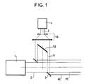
- La figure 1 représente une vue d'une partie de ce système prévue pour engendrer et mutuellement aligner les deux dits faisceaux d'entrée.
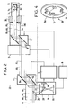
- La figure 2 représente une vue des autres parties du même système lors de la mise en oeuvre du procédé selon l'invention.
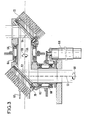
- La figure 3 représente une vue en coupe d'un ensemble optique motorisé pouvant constituer ledit émetteur ou ledit récepteur.
- La figure 4 représente une vue en perspective d'un ensemble rétroréflecteur inclus dans le même système.
- Figure 1 shows a view of part of this system provided for generating and mutually aligning the two said input beams.
- FIG. 2 represents a view of the other parts of the same system during the implementation of the method according to the invention.
- Figure 3 shows a sectional view of an assembly motorized optics which can constitute said transmitter or said receiver.
- Figure 4 shows a perspective view of a retroreflective assembly included in the same system.
Conformément à la figure 1, un laser de puissance à gaz carbonique 1 émet un faisceau de puissance infrarouge 2 constituant un rayonnement principal. Sur l'axe de ce faisceau est disposé un miroir annulaire 3, dont le plan fait un angle de 45° et dont le centre coïncide avec l'axe du faisceau.According to FIG. 1, a carbon
Un laser He Ne 4 émet un faisceau d'un rayonnement auxiliaire visible 5. Ce faisceau est agrandi en 5A puis envoyé sur un séparateur 5B qui est opaque dans sa partie centrale. On obtient ainsi un faisceau visible tubulaire 6 dont le diamètre intérieur correspond sensiblement au diamètre extérieur du faisceau de puissance. Ce faisceau est envoyé sur le miroir annulaire 3 et devient ainsi ledit faisceau auxiliaire d'entrée AE qui est coaxial audit faisceau principal d'entrée PE constitué par le faisceau 2. Un réglage mécanique fin de la position du miroir 3 permet d'aligner parfaitement les deux faisceaux à l'aide d'une cible auxiliaire au moment de l'installation des lasers près du lieu de travail.A He Ne 4 laser emits a beam of visible
La figure 2 représente les moyens utilisés pour le transport du faisceau principal jusqu'à ladite tête de traitement 30. Cette dernière est une tête de soudage. Elle comporte une enveloppe 32, une lentille de focalisation 34 et un miroir à 45 degrés 36. Elle a été introduite dans un tube à traiter 14 dans lequel une manchette doit être soudée et dont l'axe 24 constitue ledit axe d'utilisation. Ce tube est situé à l'intérieur de la boîte à eau 20 d'un générateur de vapeur non représenté comportant comme connu de nombreux autres tubes dans lesquels il peut être nécessaire d'effectuer aussi des traitements de soudage.FIG. 2 represents the means used for transporting the main beam to said
Les moyens de transport de faisceau sont constitués par deux ensembles optiques déviateurs de faisceau. Ces deux ensembles constituent ledit émetteur 11 et ledit récepteur 12. Ils sont motorisés de manière à apporter chacun une déviation qui est représentée comme nulle sur la figure 2, mais qui est commandée selon deux coordonnées angulaires. De plus le récepteur 12 est monté sur un porteur 22 qui est lui aussi motorisé de manière que sa position soit commandée selon une, deux ou trois coordonnées de position c'est-à-dire que la position du récepteur 12 est elle aussi commandée. Elle l'est de manière à centrer une fenêtre de sortie de ce récepteur sur l'axe d'utilisation.The beam transport means consist of two optical beam deflection assemblies. These two assemblies constitute said
La direction des faisceaux entrant dans l'émetteur 11 est imposée (c'est celle de l'axe du laser 1, par rapport auquel l'émetteur 11 est réglé au montage du système), de même que celle des faisceaux sortant du récepteur 12 (c'est celle de l'axe du tube à traiter 14, le récepteur étant guidé par rapport à ce tube par l'intermédiaire d'un tube 13 solidaire de ce récepteur et venant en appui contre une plaque tubulaire non représentée solidaire de ce tube). La commande des déviations angulaires de l'émetteur et du récepteur permet donc de diriger les faisceaux de sortie de l'émetteur vers le récepteur et de faire en sorte que les faisceaux d'entrée susceptibles d'être utilement reçus par le récepteur proviennent de la direction de l'émetteur, de manière à assurer une liaison optique entre l'émetteur et le récepteur. Cette liaison est réalisée par lesdits faisceaux de liaison principal PL et auxiliaire AL résultant de la déviation des faisceaux d'entrée PE et AE par l'émetteur 11.The direction of the beams entering the
Les composants du système d'alignement sont groupés en deux ensembles :The components of the alignment system are grouped into two sets:
Un ensemble fixe est situé près du trou d'homme d'accès à la boîte à eau 20. Il comprend à l'extérieur de cette boîte :
- le laser de puissance 1,
- le laser auxiliaire 4,
- le dispositif 5A, 5B, 3 utilisé pour l'alignement mutuel des faisceaux de ces deux lasers,
- un calculateur 7,
- un boîtier de contrôle vidéo 8,
- un tube 10 pénétrant dans la boîte à eau 20.A fixed assembly is located near the manhole giving access to the
- the
- the auxiliary laser 4,
the
- a computer 7,
- a video control unit 8,
- a
A l'intérieur de la boîte à eau 20 l'ensemble fixe comprend, à l'extrémité du tube 10, l'ensemble optique motorisé constituant l'émetteur 11.Inside the
Le système d'alignement comporte en outre un ensemble embarqué sur un porteur 22 installé dans la boîte à eau 20. Cet ensemble est mobile tout en étant accroché sous la plaque tubulaire. Il comprend :
- un ensemble optique motorisé constituant le récepteur 12,
- ledit tube de liaison 13
- un outillage de manchonnage 38 comportant la tête de soudage 30.The alignment system further comprises an assembly on board a
a motorized optical assembly constituting the
- said connecting
- a
Le faisceau de liaison auxiliaire AL est partiellement rétroréfléchi vers l'émetteur 11 par quatre rétroréflecteurs 15 fixés sur un support 15A (voir fig.4), lui même fixé sur le récepteur en regard de l'émetteur. Ces rétro-réflecteurs présentent la forme bien connue de coins de cubes et ont la propriété de renvoyer la lumière dans la direction d'où elle vient quelle que soit leur orientation. Ils constituent un ensemble rétroréflecteur 15B.The auxiliary connection beam AL is partially retroreflected to the
Le faisceau rétroréfléchi par l'ensemble 15B est envoyé à travers l'émetteur 11 sur un séparateur annulaire 26 qui le réfléchit, à travers une lentille 27, sur un autre séparateur 28 constitué par un miroir semi-transparent. La lumière qui a traversé le séparateur 28 forme des taches lumineuses qui constituent une image de l'ensemble rétroréflecteur 15 dans une caméra 16. Cette image comporte quatre taches qui reçoivent respectivement les flux lumineux des quatre faisceaux élémentaires renvoyés par les quatre rétroréflecteurs, et qui constituent chacune un élément d'image correspondant à l'un de ces rétroréflecteurs.The beam retroreflected by the
La caméra 16 permet notamment de comparer les flux lumineux dans ces quatre éléments d'image. Avec l'aide de cette lentille, cette caméra constitue ledit détecteur de position. Elle a des fonctions complexes d'analyse d'image et constitue un système d'analyse de position. A partir des résultats de cette analyse, par action sur les moteurs de l'émetteur, on règle parfaitement la direction pour assurer son incidence sur le récepteur. De plus, par asservissement de la commande des moteurs de l'émetteur sur l'analyse de l'image reçue en retour sur la caméra 16, on peut faire suivre en continu le récepteur par le faisceau incident.The
La partie non réfléchie du rayonnement auxiliaire traverse le récepteur 12 pour former un faisceau auxiliaire de sortie AS autour du faisceau principal de sortie PS. Ce faisceau auxilaire arrive sur un miroir de récepteur annulaire autocollimateur 17 porté par le tube 13 et situé à l'entrée du tube à traiter 14. Le tube 13 constitue ladite pièce de sortie du récepteur. Il comporte un épaulement annulaire 13A qui s'appuie par l'intermédiaire de l'outillage 38, sur la plaque tubulaire non représentée à laquelle est lié le tube 14. On assure ainsi la coïncidence de l'axe du miroir de récepteur 17 avec l'axe du tube à traiter 14.The non-reflected part of the auxiliary radiation passes through the
Le rayonnement renvoyé par ce miroir de récepteur constitue ledit faisceau de retour. Il traverse le récepteur 12 et l'émetteur 11, se réfléchit sur le séparateur 26 et, à travers la lentille 27, sur le séparateur 28 pour arriver sur une caméra 18 qui constitue ledit détecteur écartométrique et qui est située, comme la caméra 16, dans le boîtier 9. L'image formée par ce rayonnement sur cette caméra 18 est analysée par cette dernière qui fournit des signaux représentatifs de deux coordonnées de l'écart angulaire du faisceau auxiliaire de sortie AS, et donc aussi du faisceau principal de sortie PS, par rapport à l'axe d'utilisation 24.The radiation returned by this receiver mirror constitutes said return beam. It crosses the
Par action sur les moteurs du récepteur, on règle l'axe des faisceaux de sortie de manière que celui-ci soit aligné avec l'axe 24 du tube 14 qui est le même que celui du miroir 17.By acting on the receiver motors, the axis of the output beams is adjusted so that it is aligned with the
Par asservissement de la commande des moteurs du récepteur sur l'analyse de l'image formée en retour sur la caméra 18, on peut assurer l'alignement des faisceaux de sortie avec l'axe du tube à traiter 14 quels que soient les mouvements ou variations des éléments.By enslaving the control of the motors of the receiver on the analysis of the image formed in return on the camera 18, it is possible to ensure the alignment of the output beams with the axis of the tube to be treated 14 whatever the movements or variations of the elements.
Conformément à la figure 3 chaque ensemble optique motorisé tel que l'émetteur 11 ou le récepteur 12 reçoit un faisceau composite constitué par le rayonnement principal entouré par le rayonnement auxiliaire avec un axe commmun qui est dévié à chaque réflexion. Cet ensemble, par exemple l'émetteur 11, comporte les éléments suivants :
- Deux miroirs plans 52 et 54 inclinés à 45 degrés sur les axes 53 et 55 des faisceau qu'ils reçoivent et tournant autour de cet axe ce qui permet de balayer tout l'espace autour de cet ensemble comme représenté par les flèches 58 et 59.
- Des roulements 60, 62, 64 et 66 pour permettre et guider ces rotations.
- Deux moteurs 68 et 69.
- et des radiateurs 70 et 72 pour porter les miroirs 52 et 54 et pour les refroidir lorsqu'ils sont soumis au rayonnement principal.In accordance with FIG. 3, each motorized optical assembly such that the
- Two
-
- Two
- And
Une opération de soudage à l'aide du système précédemment décrit se fait comme suit, après une mise en place initiale des deux dits ensembles fixe et embarqué.A welding operation using the system described above is done as follows, after an initial installation of the two so-called fixed and on-board assemblies.
Une première opération se fait par calcul car on connait les coordonnées de la position initiale de l'ensemble embarqué.A first operation is done by calculation because we know the coordinates of the initial position of the on-board assembly.
On met cet ensemble en position convenable, par commande des moteurs du porteur 22, avec utilisation desdits moyens de guidage mécanique non représentés pour orienter convenablement le récepteur 12 par rapport au tube à traiter 14. On met aussi la tête de soudage 30 en place dans ce tube par des moyens connus sans rapport avec la présente invention.This assembly is placed in a suitable position, by controlling the motors of the
Pour la suite des opérations la liaison émetteur récepteur est assurée par les commandes précédemment décrites. Dans un premier temps seul le rayonnement auxiliaire est utilisé.For the rest of the operations, the transmitter-receiver link is provided by the commands described above. Initially only the auxiliary radiation is used.
Une fois l'alignement obtenu, le laser de puissance 1 est mis en fonctionnement.Once the alignment has been obtained, the
Un avantage de ce système est que l'on peut utiliser simultanément ou séparément les deux rayonnements. En cas d'utilisation séparée, on utilise le rayonnement auxiliaire visible uniquement pour le préréglage initial et pendant les transferts du récepteur et de la tête de soudage d'un tube à l'autre. En cas d'utilisation simultanée, pendant l'opération de soudage, le rayonnement visible permet le contrôle permanent de l'alignement et de la continuité en renvoyant l'image de tout obstacle se présentant sur le trajet des faisceaux.An advantage of this system is that the two radiations can be used simultaneously or separately. In case of separate use, the visible auxiliary radiation is only used for the initial presetting and during transfers of the receiver and the welding head from one tube to another. In the case of simultaneous use, during the welding operation, visible radiation allows permanent control of the alignment and continuity by returning the image of any obstacle occurring on the path of the beams.
Un autre avantage est que l'on peut contrôler les faisceaux jusqu'au miroir de récepteur 17 situé en aval du récepteur et qui peut être placé très près de la tête de traitement, dans l'exemple la tête de soudage.Another advantage is that the beams can be checked up to the
Des informations utiles peuvent être tirées de la demande de brevet européen précédemment indiquée.Useful information can be obtained from the European patent application indicated above.
Claims (10)
- un émetteur (11) pour recevoir au moins un faisceau d'entrée (AE) et pour le transmettre sous la forme d'un faisceau de liaison (AL),
- un récepteur mobile (12) à distance dudit émetteur,
- et des moyens de commande pour que ce récepteur reçoive ce faisceau de liaison et le transforme en un faisceau de sortie (PS) aligné sur un axe d'utilisation (24),
- ledit système d'alignement étant caractérisé par le fait que lesdits moyens de commande permettent un alignement précis dudit faisceau de sortie sur ledit axe d'utilisation à l'aide de moyens de détection de lumière simplifiés (16, 18).1 / Optical beam alignment system, this system comprising:
- a transmitter (11) for receiving at least one input beam (AE) and for transmitting it in the form of a connecting beam (AL),
- a mobile receiver (12) remote from said transmitter,
- and control means so that this receiver receives this link beam and transforms it into an output beam (PS) aligned on a use axis (24),
- Said alignment system being characterized by the fact that said control means allow precise alignment of said output beam on said axis of use using simplified light detection means (16, 18).
- ledit émetteur (11) pour recevoir un faisceau principal d'entrée (2) constitué d'un rayonnement principal à utiliser et pour le transmettre sous la forme d'un faisceau principal de liaison (PL) commandable en direction,
- ledit récepteur (12) pour recevoir ce faisceau principal de liaison, et pour lui appliquer une déviation angulaire commandable propre à le transformer en un faisceau principal de sortie (PS) aligné sur un axe d'utilisation (24) lié à une structure extérieure au dit système d'alignement,
- et des moyens d'orientation optique comportant :
- une source auxiliaire (4) pour engendrer un rayonnement auxiliaire sous la forme d'un faisceau auxiliaire d'entrée (6) aligné sur le trajet dudit faisceau principal d'entrée de manière que ce faisceau auxiliaire d'entrée soit transformé par ledit émetteur (11) en un faisceau auxiliaire de liaison (AL) aligné sur le trajet du dit faisceau principal de liaison (PL), et que ce faisceau auxiliaire de liaison soit transformé par ledit récepteur en un faisceau auxiliaire de sortie (AS) aligné sur le trajet dudit faisceau principal de sortie,
- des moyens de commande d'émetteur (15, 16, 7) sensibles à une fraction du rayonnement dudit faisceau auxiliaire de liaison reçu par ledit récepteur pour permettre de commander ledit émetteur de manière que lesdits faisceaux auxiliaire et principal de liaison soit dirigés vers ce récepteur,
- et des moyens de commande de récepteur (17, 18, 7) sensibles à une fraction du rayonnement dudit faisceau auxiliaire de liaison reçu par ledit récepteur pour permettre de commander ladite déviation angulaire de manière que lesdits faisceaux principal et auxiliaire de sortie soient alignés sur ledit axe d'utilisation,
- ledit système d'alignement étant caractérisé par le fait que ledit faisceau auxiliaire d'entrée (AE) est un faisceau tubulaire formé coaxialement autour dudit faisceau principal d'entrée (PE), lesdits moyens de commande d'émetteur et de récepteur étant placés en dehors du trajet dudit rayonnement principal.2 / Alignment system according to claim 1, this system comprising:
said transmitter (11) for receiving a main input beam (2) consisting of a main radiation to be used and for transmitting it in the form of a main connecting beam (PL) controllable in direction,
- Said receiver (12) to receive this main connection beam, and to apply to it a controllable angular deflection capable of transforming it into a main output beam (PS) aligned on an axis of use (24) linked to an external structure to the said alignment system,
- And optical orientation means comprising:
- an auxiliary source (4) for generating auxiliary radiation in the form of an auxiliary input beam (6) aligned on the path of said main input beam so that this auxiliary input beam is transformed by said emitter (11) into an auxiliary connecting beam (AL) aligned on the path of said main connecting beam (PL), and that this auxiliary connecting beam is transformed by said receiver into an auxiliary output beam (AS) aligned on the path of said main output beam,
- transmitter control means (15, 16, 7) sensitive to a fraction of the radiation of said auxiliary link beam received by said receiver to enable said transmitter to be controlled so that said auxiliary and main link beams are directed towards this receiver,
- And receiver control means (17, 18, 7) sensitive to a fraction of the radiation of said auxiliary link beam received by said receiver to enable said angle deviation to be controlled so that said main and auxiliary output beams are aligned with said axis of use,
said alignment system being characterized in that said auxiliary input beam (AE) is a tubular beam formed coaxially around said main input beam (PE), said transmitter and receiver control means being placed outside the path of said main radiation.
- des moyens de renvoi (15, 17) de la lumière dudit faisceau auxiliaire vers ledit émetteur (11),
- et un séparateur annulaire (26) qui entoure ledit faisceau principal d'entrée (PE) et qui dirige la lumière renvoyée par lesdits moyens de renvoi vers des moyens de détection et d'analyse (16, 18, 7).
3 / System according to claim 2, characterized in that said transmitter and receiver control means comprise:
- means for returning (15, 17) the light from said auxiliary beam to said transmitter (11),
- And an annular separator (26) which surrounds said main input beam (PE) and which directs the light returned by said return means towards detection and analysis means (16, 18, 7).
- ledit émetteur (11) pour recevoir au moins un faisceau d'entrée (AE) et pour le transmettre sous la forme d'un faisceau de liaison (AL) commandable en direction,
- ledit récepteur (12),
- et des moyens de commande d'émetteur (15, 16, 7) sensibles à l'irradiation dudit récepteur par ledit faisceau de liaison pour permettre de commander ledit émetteur de manière qu'il dirige ce faisceau vers ce récepteur,
- ledit système d'alignement étant caractérisé par le fait que lesdits moyens de commande d'émetteur comportent un ensemble rétroréflecteur (15B) lié audit récepteur (12) et constitué de plusieurs rétroréflecteurs (15) renvoyant chacun une partie correspondante dudit faisceau de liaison (AL) dans la direction même de ce faisceau de liaison pour constituer un faisceau rétroréfléchi,
- et un détecteur de faisceau rétroréfléchi lié audit émetteur (11) et formant une image dudit ensemble rétroréflecteur sur un système d'analyse d'image (16, 7) permettant de détecter la position dudit récepteur (12) par rapport au dit faisceau de liaison.4 / Alignment system according to claim 1, this system comprising:
- said transmitter (11) to receive at least one input beam (AE) and to transmit it in the form of a link beam (AL) controllable in direction,
- said receiver (12),
- and transmitter control means (15, 16, 7) sensitive to the irradiation of said receiver by said link beam in order to allow said transmitter to be controlled so that it directs this beam to this receiver,
- said alignment system being characterized by the fact that said transmitter control means comprise a retroreflector assembly (15B) linked to said receiver (12) and consisting of several retroreflectors (15) each returning a corresponding part of said link beam (AL) in the same direction of this link beam to constitute a retroreflected beam,
- And a retroreflective beam detector linked to said emitter (11) and forming an image of said retroreflective assembly on an image analysis system (16, 7) making it possible to detect the position of said receiver (12) relative to said beam of liaison.
- ledit émetteur (11),
- ledit récepteur (12) recevant ce faisceau de liaison, et lui appliquant une déviation angulaire commandable pour le transformer en ledit faisceau de sortie (PS),
- et des moyens de commande de récepteur pour permettre de commander ladite déviation commandable de manière à aligner ledit faisceau de liaison sur un axe d'utilisation (24) lié à une structure (14) extérieure audit système d'alignement, ces moyens de commande de récepteur comportant eux-mêmes :
- un miroir de récepteur lié audit récepteur (12) pour renvoyer une partie de la lumière dudit faisceau de liaison vers ledit émetteur (11) sous la forme d'un faisceau de retour dont la direction est affectée par ladite déviation commandable,
- et un détecteur écartométrique (18) lié audit émetteur et sensible aux déviations de ce faisceau de retour,
- ledit système d'alignement étant caractérisé par le fait que ledit miroir de récepteur (17) est placé sur le trajet dudit faisceau de sortie (AS) de sorte que ledit faisceau de retour est formé à partir de ce faisceau de sortie et traverse ledit récepteur (12) en retour, ce miroir présentant un axe perpendiculaire à sa surface et étant monté pour s'orienter par rapport à ladite structure extérieure (14) de manière à aligner son axe sur ledit axe d'utilisation (24).8 / Alignment system according to claim '1, this system comprising:
- said transmitter (11),
- said receiver (12) receiving this link beam, and applying to it a controllable angular deviation to transform it into said output beam (PS),
- And receiver control means to allow to control said controllable deflection so as to align said connecting beam on a use axis (24) linked to a structure (14) external to said alignment system, these control means of receiver comprising themselves:
a receiver mirror linked to said receiver (12) for returning part of the light from said link beam to said transmitter (11) in the form of a return beam, the direction of which is affected by said controllable deflection,
- and a deviation detector (18) linked to said transmitter and sensitive to deviations of this return beam,
- said alignment system being characterized in that said receiver mirror (17) is placed on the path of said output beam (AS) so that said return beam is formed from this output beam and passes through said receiver (12) in return, this mirror having an axis perpendicular to its surface and being mounted to orient itself relative to said external structure (14) so as to align its axis with said axis of use (24).
- on introduit dans une pièce à traiter (14) une tête de traitement (30),
- on engendre un rayonnement de traitement (PE) à distance de cette pièce à traiter,
- et on aligne un faisceau de ce rayonnement selon un axe d'utilisation (24) lié à cette pièce à traiter pour alimenter cette tête de traitement,
- ce procédé étant caractérisé par le fait qu'on aligne ledit faisceau à l'aide d'un système d'alignement choisi selon l'une quelconque des revendications précédentes.10 / A method of radiation treatment, in particular welding, inside parts of difficult access, in particular tubes of a nuclear power plant, this method comprising the following operations,
a treatment head (30) is introduced into a part to be treated (14),
- a treatment radiation (PE) is generated at a distance from this part to be treated,
- and a beam of this radiation is aligned along an axis of use (24) linked to this part to be treated in order to supply this treatment head,
- This method being characterized by the fact that said beam is aligned using an alignment system chosen according to any one of the preceding claims.
Applications Claiming Priority (2)
| Application Number | Priority Date | Filing Date | Title |
|---|---|---|---|
| FR8802473A FR2627874B1 (en) | 1988-02-29 | 1988-02-29 | POWER BEAM ALIGNMENT SYSTEM |
| FR8802473 | 1988-02-29 |
Publications (1)
| Publication Number | Publication Date |
|---|---|
| EP0331962A1 true EP0331962A1 (en) | 1989-09-13 |
Family
ID=9363730
Family Applications (1)
| Application Number | Title | Priority Date | Filing Date |
|---|---|---|---|
| EP89102934A Ceased EP0331962A1 (en) | 1988-02-29 | 1989-02-20 | Power beam alignment system |
Country Status (10)
| Country | Link |
|---|---|
| US (1) | US5085509A (en) |
| EP (1) | EP0331962A1 (en) |
| JP (1) | JPH01258888A (en) |
| KR (1) | KR890013493A (en) |
| CN (1) | CN1035567A (en) |
| CA (1) | CA1316990C (en) |
| DK (1) | DK91489A (en) |
| FR (1) | FR2627874B1 (en) |
| SU (1) | SU1713425A3 (en) |
| ZA (1) | ZA891536B (en) |
Cited By (3)
| Publication number | Priority date | Publication date | Assignee | Title |
|---|---|---|---|---|
| FR2679809A1 (en) * | 1991-08-01 | 1993-02-05 | France Etat Armement | Device for observing a zone of interaction between a laser beam and material, and laser-beam treatment device and method using this observation device |
| WO2018087256A1 (en) * | 2016-11-11 | 2018-05-17 | Trumpf Laser- Und Systemtechnik Gmbh | Method for determining a beam profile of a laser beam, and processing machine |
| WO2018086996A1 (en) * | 2016-11-11 | 2018-05-17 | Trumpf Laser- Und Systemtechnik Gmbh | Method for calibrating a scanner, and machining device |
Families Citing this family (12)
| Publication number | Priority date | Publication date | Assignee | Title |
|---|---|---|---|---|
| JP2559285B2 (en) * | 1990-03-29 | 1996-12-04 | 株式会社イセキ開発工機 | Shield type tunnel excavator |
| US5386221A (en) * | 1992-11-02 | 1995-01-31 | Etec Systems, Inc. | Laser pattern generation apparatus |
| US5430270A (en) * | 1993-02-17 | 1995-07-04 | Electric Power Research Institute, Inc. | Method and apparatus for repairing damaged tubes |
| US5461472A (en) * | 1993-06-28 | 1995-10-24 | At&T Ipm Corp. | Method and apparatus for measuring the parallelism of two surfaces |
| US5642297A (en) * | 1994-12-12 | 1997-06-24 | Gurley Precision Instruments, Inc. | Apparatus and method for measuring the kinematic accuracy in machines and mechanisms using absolute encoders |
| JP3560135B2 (en) * | 1999-03-23 | 2004-09-02 | 日産自動車株式会社 | Quality monitoring method for YAG laser welds |
| US7279721B2 (en) | 2005-04-13 | 2007-10-09 | Applied Materials, Inc. | Dual wavelength thermal flux laser anneal |
| CN101164111B (en) * | 2005-04-19 | 2010-06-16 | 皇家飞利浦电子股份有限公司 | Device for directing radiation to a layer, apparatus with such device and method using such apparatus |
| JP6512673B2 (en) * | 2015-03-27 | 2019-05-15 | オリンパス株式会社 | Eccentricity measuring device and eccentricity measuring method |
| DE102015016274B4 (en) * | 2015-12-16 | 2023-10-19 | Mbda Deutschland Gmbh | Optical system and method for adjusting a signal beam |
| DE102018205403A1 (en) * | 2018-04-11 | 2019-10-17 | Trumpf Laser- Und Systemtechnik Gmbh | Method for calibrating a processing machine and processing machine |
| US10989528B2 (en) * | 2019-08-27 | 2021-04-27 | Raytheon Company | High speed beam component-resolved profile and position sensitive detector |
Citations (3)
| Publication number | Priority date | Publication date | Assignee | Title |
|---|---|---|---|---|
| EP0154866A1 (en) * | 1984-02-24 | 1985-09-18 | Firma Carl Zeiss | Laser-misalignment compensating device |
| EP0217077A2 (en) * | 1985-08-23 | 1987-04-08 | Firma Carl Zeiss | Device for correcting the position of a laser beam guided by an articulated optical system |
| EP0238171A1 (en) * | 1986-01-23 | 1987-09-23 | Westinghouse Electric Corporation | Laser welding head for sleeve-to-tube welding |
Family Cites Families (8)
| Publication number | Priority date | Publication date | Assignee | Title |
|---|---|---|---|---|
| US3844660A (en) * | 1972-11-16 | 1974-10-29 | Zygo Corp | Method and apparatus for aligning an interferometer mirror |
| US3892488A (en) * | 1974-02-22 | 1975-07-01 | Us Air Force | Laser site marking system |
| JPS57137092A (en) * | 1981-02-16 | 1982-08-24 | Olympus Optical Co Ltd | Visible guide beam projector for invisible laser device |
| US4466739A (en) * | 1982-02-26 | 1984-08-21 | Kasner William H | Laser beam alignment system |
| FR2541468B1 (en) * | 1983-02-17 | 1986-07-11 | Commissariat Energie Atomique | DEVICE FOR ALIGNING A LASER BEAM THROUGH OPTICAL SIGHTING MEANS, METHOD FOR LOCATING THE LASER BEAM EMISSION AXIS AND METHOD FOR IMPLEMENTING THE DEVICE, FOR CONTROLLING ALIGNMENT |
| JPS6047482A (en) * | 1983-08-26 | 1985-03-14 | Toshiba Corp | Laser irradiating device |
| DE3406676A1 (en) * | 1984-02-24 | 1985-09-05 | Fa. Carl Zeiss, 7920 Heidenheim | DEVICE FOR CORRECTING THE POSITION OF A LASER BEAM GUIDED BY A JOINT OPTICS |
| US4772122A (en) * | 1986-08-18 | 1988-09-20 | Westinghouse Electric Corp. | Alignment technique for laser beam optics |
-
1988
- 1988-02-29 FR FR8802473A patent/FR2627874B1/en not_active Expired - Fee Related
-
1989
- 1989-02-20 EP EP89102934A patent/EP0331962A1/en not_active Ceased
- 1989-02-27 SU SU894613625A patent/SU1713425A3/en active
- 1989-02-27 DK DK091489A patent/DK91489A/en not_active Application Discontinuation
- 1989-02-28 KR KR1019890002416A patent/KR890013493A/en not_active Application Discontinuation
- 1989-02-28 ZA ZA891536A patent/ZA891536B/en unknown
- 1989-02-28 JP JP1045564A patent/JPH01258888A/en active Pending
- 1989-02-28 CA CA000592296A patent/CA1316990C/en not_active Expired - Fee Related
- 1989-02-28 CN CN89100937A patent/CN1035567A/en active Pending
- 1989-02-28 US US07/316,749 patent/US5085509A/en not_active Expired - Fee Related
Patent Citations (3)
| Publication number | Priority date | Publication date | Assignee | Title |
|---|---|---|---|---|
| EP0154866A1 (en) * | 1984-02-24 | 1985-09-18 | Firma Carl Zeiss | Laser-misalignment compensating device |
| EP0217077A2 (en) * | 1985-08-23 | 1987-04-08 | Firma Carl Zeiss | Device for correcting the position of a laser beam guided by an articulated optical system |
| EP0238171A1 (en) * | 1986-01-23 | 1987-09-23 | Westinghouse Electric Corporation | Laser welding head for sleeve-to-tube welding |
Non-Patent Citations (2)
| Title |
|---|
| PATENT ABSTRACTS OF JAPAN vol. 6, no. 236 (M-173)(1114) 25 novembre 1982, & JP-A-57 137092 (OLYMPUS KOGAKU KOGYO K.K.) 24 août 1982, * |
| PATENT ABSTRACTS OF JAPAN vol. 9, no. 178 (E-330)(1901) 23 juillet 1985, & JP-A-60 047482 (TOSHIBA K.K.) 14 mars 1985, * |
Cited By (8)
| Publication number | Priority date | Publication date | Assignee | Title |
|---|---|---|---|---|
| FR2679809A1 (en) * | 1991-08-01 | 1993-02-05 | France Etat Armement | Device for observing a zone of interaction between a laser beam and material, and laser-beam treatment device and method using this observation device |
| WO2018087256A1 (en) * | 2016-11-11 | 2018-05-17 | Trumpf Laser- Und Systemtechnik Gmbh | Method for determining a beam profile of a laser beam, and processing machine |
| WO2018086996A1 (en) * | 2016-11-11 | 2018-05-17 | Trumpf Laser- Und Systemtechnik Gmbh | Method for calibrating a scanner, and machining device |
| CN109937100A (en) * | 2016-11-11 | 2019-06-25 | 通快激光与系统工程有限公司 | Method and processing machine for calibration scan device |
| US10739191B2 (en) | 2016-11-11 | 2020-08-11 | Trumpf Laser- Und Systemtechnik Gmbh | Determining a beam profile of a laser beam |
| CN109937100B (en) * | 2016-11-11 | 2022-03-01 | 通快激光与系统工程有限公司 | Method and machine tool for calibrating a scanning device |
| CN114192970A (en) * | 2016-11-11 | 2022-03-18 | 通快激光与系统工程有限公司 | Method and machine tool for calibrating a scanning device |
| US11899421B2 (en) | 2016-11-11 | 2024-02-13 | Trumpf Laser- Und Systemtechnik Gmbh | Calibrating a scanner device |
Also Published As
| Publication number | Publication date |
|---|---|
| FR2627874A1 (en) | 1989-09-01 |
| JPH01258888A (en) | 1989-10-16 |
| KR890013493A (en) | 1989-09-23 |
| US5085509A (en) | 1992-02-04 |
| CA1316990C (en) | 1993-04-27 |
| SU1713425A3 (en) | 1992-02-15 |
| DK91489A (en) | 1989-08-30 |
| ZA891536B (en) | 1989-11-29 |
| CN1035567A (en) | 1989-09-13 |
| DK91489D0 (en) | 1989-02-27 |
| FR2627874B1 (en) | 1995-06-16 |
Similar Documents
| Publication | Publication Date | Title |
|---|---|---|
| EP0331962A1 (en) | Power beam alignment system | |
| EP0419320B1 (en) | Automatic harmonizing device for an opto-electronic system | |
| FR2599139A1 (en) | AXIAL ALIGNMENT ASSISTANCE APPARATUS FOR REMOTE CONTROL OPERATIONS AND RELATED METHOD | |
| EP0898726B1 (en) | Aperture-synthesis diffractive optical device and laser cutting device comprising same | |
| FR2581768A1 (en) | BIDIRECTIONAL OPTOELECTRIC COMPONENT FORMING OPTICAL COUPLER | |
| EP0712009A1 (en) | Integrated angular deviation measurement system | |
| FR2669427A1 (en) | TWO OPTICAL OPTICAL ALIGNMENT CONTROL DEVICE AND LASER DESIGNATION SYSTEM EQUIPPED WITH SUCH AN INSPECTION DEVICE. | |
| FR2659752A1 (en) | OPTICAL IMAGE FORMING SYSTEMS. | |
| EP0995145B1 (en) | Diffractive optics with synthetic aperture and variable focal length and laser cutting device incorporating such an optics | |
| CA2187339C (en) | Radiation beam position sensor | |
| FR2606167A1 (en) | COMPACT OPTICAL APPARATUS FOR TRACKING A TOOL ALONG A MOVEMENT LINE ON A WORKPIECE | |
| EP0702246B1 (en) | Portable device for measuring the backscattering of light | |
| FR2861851A1 (en) | Obstacles detection device for aircraft e.g. helicopter, has scanning unit formed with polygonal mirror having reflecting surfaces, and generator whose light beam passes via one surface in response to rotating position of mirror | |
| CA2308864A1 (en) | Process and device for detecting axis harmonization errors in an optical instrument | |
| EP0509933B1 (en) | Procedure for the alignment of a laserr beam to the opening of a nozzle and focussing head matched for machining by laser beam | |
| EP0321048A1 (en) | High power illuminating device for a camera | |
| US8792099B1 (en) | Method and apparatus for phase detection in a beam steering laser array | |
| EP1045588A1 (en) | Transmission device for digital video images | |
| FR2576114A1 (en) | OPTICAL MECHANICAL ANALYZER HAVING A FIELD OF FIXED TELEMETRY | |
| EP0038297A1 (en) | Method of deburring a sharp instrument, apparatus to use the method and sharp instrument obtained by the method | |
| FR2690584A1 (en) | Digital word detector for laser beam communication or data acquisition system - has focussing system to central hole for aligning two light detectors on same axis positionally adjusting laser beam | |
| EP2232308B1 (en) | Laser imaging system | |
| EP0545788B1 (en) | Procedure and device for positioning a tool in front of the axis of a tube | |
| EP0057626A2 (en) | Luminous target for optical threedimensional measuring techniques and measuring method | |
| EP0165116B1 (en) | System for optical detection from a distance |
Legal Events
| Date | Code | Title | Description |
|---|---|---|---|
| PUAI | Public reference made under article 153(3) epc to a published international application that has entered the european phase |
Free format text: ORIGINAL CODE: 0009012 |
|
| AK | Designated contracting states |
Kind code of ref document: A1 Designated state(s): BE CH DE ES GB IT LI NL SE |
|
| 17P | Request for examination filed |
Effective date: 19900305 |
|
| 17Q | First examination report despatched |
Effective date: 19910705 |
|
| STAA | Information on the status of an ep patent application or granted ep patent |
Free format text: STATUS: THE APPLICATION HAS BEEN REFUSED |
|
| 18R | Application refused |
Effective date: 19951216 |