EP0331657A2 - Kontrolleinrichtung zum Positionieren von zwei oder mehr Werkzeugen in einer Maschine, speziell einer Jalousieherstellungsmaschine - Google Patents
Kontrolleinrichtung zum Positionieren von zwei oder mehr Werkzeugen in einer Maschine, speziell einer Jalousieherstellungsmaschine Download PDFInfo
- Publication number
- EP0331657A2 EP0331657A2 EP19890850063 EP89850063A EP0331657A2 EP 0331657 A2 EP0331657 A2 EP 0331657A2 EP 19890850063 EP19890850063 EP 19890850063 EP 89850063 A EP89850063 A EP 89850063A EP 0331657 A2 EP0331657 A2 EP 0331657A2
- Authority
- EP
- European Patent Office
- Prior art keywords
- machine
- gear
- setting
- units
- gear unit
- Prior art date
- Legal status (The legal status is an assumption and is not a legal conclusion. Google has not performed a legal analysis and makes no representation as to the accuracy of the status listed.)
- Granted
Links
Images

Classifications
-
- B—PERFORMING OPERATIONS; TRANSPORTING
- B21—MECHANICAL METAL-WORKING WITHOUT ESSENTIALLY REMOVING MATERIAL; PUNCHING METAL
- B21D—WORKING OR PROCESSING OF SHEET METAL OR METAL TUBES, RODS OR PROFILES WITHOUT ESSENTIALLY REMOVING MATERIAL; PUNCHING METAL
- B21D37/00—Tools as parts of machines covered by this subclass
- B21D37/04—Movable or exchangeable mountings for tools
-
- E—FIXED CONSTRUCTIONS
- E06—DOORS, WINDOWS, SHUTTERS, OR ROLLER BLINDS IN GENERAL; LADDERS
- E06B—FIXED OR MOVABLE CLOSURES FOR OPENINGS IN BUILDINGS, VEHICLES, FENCES OR LIKE ENCLOSURES IN GENERAL, e.g. DOORS, WINDOWS, BLINDS, GATES
- E06B9/00—Screening or protective devices for wall or similar openings, with or without operating or securing mechanisms; Closures of similar construction
- E06B9/24—Screens or other constructions affording protection against light, especially against sunshine; Similar screens for privacy or appearance; Slat blinds
- E06B9/26—Lamellar or like blinds, e.g. venetian blinds
- E06B9/266—Devices or accessories for making or mounting lamellar blinds or parts thereof
-
- B—PERFORMING OPERATIONS; TRANSPORTING
- B21—MECHANICAL METAL-WORKING WITHOUT ESSENTIALLY REMOVING MATERIAL; PUNCHING METAL
- B21J—FORGING; HAMMERING; PRESSING METAL; RIVETING; FORGE FURNACES
- B21J15/00—Riveting
-
- Y—GENERAL TAGGING OF NEW TECHNOLOGICAL DEVELOPMENTS; GENERAL TAGGING OF CROSS-SECTIONAL TECHNOLOGIES SPANNING OVER SEVERAL SECTIONS OF THE IPC; TECHNICAL SUBJECTS COVERED BY FORMER USPC CROSS-REFERENCE ART COLLECTIONS [XRACs] AND DIGESTS
- Y10—TECHNICAL SUBJECTS COVERED BY FORMER USPC
- Y10T—TECHNICAL SUBJECTS COVERED BY FORMER US CLASSIFICATION
- Y10T29/00—Metal working
- Y10T29/39—Venetian blind assembling
Definitions
- a number of tool units must be set in different positions along a machine bed.
- these tool units should be movable proportionally relative to one another along the machine bed, such that they can be placed in optionally selectable and yet relatively proportional positions along the machine bed.
- Venetian blind production machine which constitutes the subject matter of the European Patent EP-B-0,182,805 and which comprises a feeding device for supplying from a supply reel at least one metal strip intermittently in the longitudinal direction of the metal strip through a number of ladder tapes, and a punching station with means for punching lift cord holes in the free end portion of the metal strip before this end portion is inserted in the ladder tapes, as well as a separating station for separating from said free end portion of the metal strip the individual Venetian blind slats inserted in the ladder tapes.
- the punching station of this Venetian blind production machine has at least two groups of punching tools for simultaneously punching lift cord holes in at least two successive Venetian blind slats, said separating station having at least a corresponding number of separating punches for simultaneously separating Venetian blind slats for the same number of simultaneously produced Venetian blinds.
- the different tools must be set in exact positions along the machine bed. This operation is time-consuming, and errors are easily made. If the punching of lift cord holes takes place in a machine section ahead of the threading tools, the setting operation will be far more complicated and even more time-consuming.
- the present invention aims at providing a control device by which two or more tool units in a machine, especially a Venetian blind production machine, can be set in different optionally selectable and relatively proportional positions along a machine bed.
- the control device thus comprises a number of series-connected setting screws and gear units for proportional displacement of the tool units along the machine bed during operation by means of a drive motor.
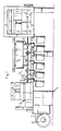
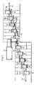
- FIG. 1 The embodiment illustrated in the drawings of the device according to the invention is used for a Venetian blind production machine which comprises a frame 1 having an elongate machine bed 2 along which a number of tool units 3 can be clamped in desired positions paying regard to the Venetian blind production concerned.
- the different units are interconnected by a main shaft 4 which is driven by a motor (not shown) accommodated in a housing 5.
- a supply reel 6 At the infeed end of the machine, a supply reel 6 is mounted for supplying a metal strip 7 which is fed in the longitudinal direction of the machine in a manner explained in detail in the above-mentioned European patent EP-B-0,182,805 which is included by reference. For particulars in this respect, reference is therefore made to that publication.
- two or more tool units 3 of the machine can be set by means of series-connected setting screws 10-14 and gear units 15-19, the latter being mounted in carriages 20 slidable along the machine bed.
- the number of tool units may be optionally varied.
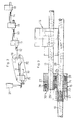
- Figs 2 and 3 illustrate a first setting screw 10 which, at its left-hand end as shown in the drawing, is connected with a drive motor 21.
- the screw 10 engages with a nut 22 fixedly connected with the housing 23 of the gear unit 15.
- the screw then extends through the hub of a gear wheel 24 of the gear unit 15.
- the gear wheel is nonrotatably but displaceably connected with the screw 10 by means of a wedge 25 which engages with a longitudinal keyway extending along the entire control length of the screw 10.
- the gear wheel 24 is mounted in the housing 23 by means of ball bearings 28 and engages with a second gear wheel 27 which also is mounted in the housing 23 by means of ball bearings 28.
- the gear wheel 27 is nonrotatably connected, by means of a wedge 29, with the succeeding setting screw 11 which is nonrotatably locked to the gear wheel 27 by means of a pin 30.
- the screws 10 and 11 are interconnected by means of two meshing gear wheels, the screws 10 are oppositely threaded.
- the housings 16, 17, 18 and 19 are designed in accordance with the housing 15 and need not therefore be described in detail. It is essential that the screws are oppositely threaded two and two. However, if each gear unit is provided with an additional gear wheel, the screws 10, 11 may be threaded in the same direction.
- the preferred gear ratio in the embodiment illustrated is 1:1, but for some applications other gear ratios may be desired for specific tool units or for all tool units. Adapting the gear ratio to existing requirements is professional routine.
- the carriages 20 and the machine bed 2 are so wide that six screws can be mounted side by side and with the same centre distances. In the embodiment illustrated, however, only five screws are used.
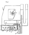
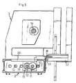
- Figs 4 and 5 also show that the main shaft 4 of the machine has a longitudinal keyway 31 engaged by a wedge (not shown) on each tool unit 3 for operating a tool mounted therein.
- Figs 1 and 4-6 show a number of supports 32 which are mounted along the machine bed 2 and can be automatically folded up and down during movement of the carriages 20 along the machine bed.
- the supports are pivotally connected with the machine bed by means of a pivot pin 33 and are spring-biased, by means of a spring mechanism (not shown), in counterclockwise direction (Figs 4 and 5), which means that they are biased upwardly to the position shown in Fig. 5.
- Fig. 4 shows one of these supports in folded-down position.
- the supports are automatically folded down by means of a cam 34 which is mounted on the carriage 20 and formed with an oblique cam surface 35 adapted to engage with a corresponding cam surface 36 on each support 32. In this manner, the supports 32 will be folded up and down during movement of the carriages 20 along the machine bed.
- Fig. 7 illustrates a further embodiment of the device according to the invention.
- the control device is used for two groups of tool units mounted on two sets of gear units 15-19 and 15′-19′ which are operated by a centrally positioned drive motor 21.
- the device may have the same construction as described above in connection with the first-mentioned embodiment.
- the drive motor may be a manually operated source of motive power, such as a crank, or some other rotary type power source, such as an electric motor.
- a crank or some other rotary type power source, such as an electric motor.
- an electric motor controlled by a computer or the like which in that case may be programmable to store data about different types of products that can be manufactured in the machine.
- FIG. 7 shows how the control device according to the invention can be used for two groups of tool units arranged at both ends of a centrally positioned drive unit.
- a further possibility of using the control device for several sets of tools is to mount the tools side by side in each tool unit 3.
- This embodiment may be advantageous for example when it is desired, in the production of Venetian blinds, to punch and cut mounting rails and the like in the same machine which subsequently is to be used for punching and cutting of blind slats in the manner disclosed in for example the above-mentioned European patent EP-B-0,182,805.
- each tool unit 3 may also comprise juxtaposed tools for different slat widths, for example 15 mm, 25 mm, 35 mm, 50 mm etc.
Landscapes
- Engineering & Computer Science (AREA)
- Structural Engineering (AREA)
- Architecture (AREA)
- Civil Engineering (AREA)
- Mechanical Engineering (AREA)
- Blinds (AREA)
- Multi-Process Working Machines And Systems (AREA)
- Transmission Devices (AREA)
- Control Of Position Or Direction (AREA)
Applications Claiming Priority (2)
| Application Number | Priority Date | Filing Date | Title |
|---|---|---|---|
| SE8800704 | 1988-02-29 | ||
| SE8800704A SE458379B (sv) | 1988-02-29 | 1988-02-29 | Regleranordning foer instaellning av tvaa eller flera verktygsenheter i en maskin, saerskilt persienntillverkningsmaskin |
Publications (3)
| Publication Number | Publication Date |
|---|---|
| EP0331657A2 true EP0331657A2 (de) | 1989-09-06 |
| EP0331657A3 EP0331657A3 (de) | 1991-04-17 |
| EP0331657B1 EP0331657B1 (de) | 1992-12-30 |
Family
ID=20371532
Family Applications (1)
| Application Number | Title | Priority Date | Filing Date |
|---|---|---|---|
| EP89850063A Expired - Lifetime EP0331657B1 (de) | 1988-02-29 | 1989-02-23 | Kontrolleinrichtung zum Positionieren von zwei oder mehr Werkzeugen in einer Maschine, speziell einer Jalousieherstellungsmaschine |
Country Status (9)
| Country | Link |
|---|---|
| US (1) | US5060353A (de) |
| EP (1) | EP0331657B1 (de) |
| JP (1) | JPH0710485B2 (de) |
| KR (1) | KR960006992B1 (de) |
| AU (1) | AU603729B2 (de) |
| CA (1) | CA1319501C (de) |
| DE (1) | DE68904096T2 (de) |
| DK (1) | DK166633B1 (de) |
| SE (1) | SE458379B (de) |
Cited By (2)
| Publication number | Priority date | Publication date | Assignee | Title |
|---|---|---|---|---|
| WO1992017676A1 (en) * | 1991-04-08 | 1992-10-15 | Norbert Marocco | Method and apparatus for the manufacture of blinds |
| EP1813765A1 (de) * | 2006-01-27 | 2007-08-01 | ZEBR s.r.o. | Vorrichtung zum Lochen von dünnwandigen, endlosen Bändern |
Families Citing this family (3)
| Publication number | Priority date | Publication date | Assignee | Title |
|---|---|---|---|---|
| SE468401B (sv) * | 1991-05-08 | 1993-01-11 | Sani Maskiner Ab | Persienntillverkningsmaskin samt stansanordning foer denna |
| GB2279896A (en) * | 1993-03-23 | 1995-01-18 | Harrison Keith | Tooling apparatus |
| CN112893581B (zh) * | 2021-01-20 | 2022-10-28 | 深圳市松青锌镁铝精密压铸有限公司 | 一种效率高的多工位工件加工用循环冲压设备 |
Family Cites Families (7)
| Publication number | Priority date | Publication date | Assignee | Title |
|---|---|---|---|---|
| GB713802A (en) * | 1952-02-15 | 1954-08-18 | Levolor Lorentzen Inc | Machine useful in the manufacture of venetian blinds |
| US3654830A (en) * | 1970-06-24 | 1972-04-11 | Engel Ind Inc | Sheet metal blanking and shearing machine |
| US4386454A (en) * | 1980-07-21 | 1983-06-07 | Hopper Thomas P | Apparatus for assembling a shade device |
| SE441941B (sv) * | 1984-04-13 | 1985-11-18 | Berndt Roland Nilsson | Persienntillverkningsmaskin |
| US4615087A (en) * | 1985-09-12 | 1986-10-07 | Chang A Shen | Continuous mechanism for re-moulding, length-setting and assembling blind's |
| US4711005A (en) * | 1985-09-12 | 1987-12-08 | Joanna Western Mills Company | Method and apparatus for making slats for window blinds and the like from a continuous web of plastic material |
| US4823449A (en) * | 1987-11-09 | 1989-04-25 | Chang A Shen | Automatic and continuous mechanism for processing and assembling venetian blind slats |
-
1988
- 1988-02-29 SE SE8800704A patent/SE458379B/sv not_active IP Right Cessation
-
1989
- 1989-02-23 DE DE8989850063T patent/DE68904096T2/de not_active Expired - Fee Related
- 1989-02-23 EP EP89850063A patent/EP0331657B1/de not_active Expired - Lifetime
- 1989-02-24 DK DK090889A patent/DK166633B1/da not_active IP Right Cessation
- 1989-02-28 CA CA000592255A patent/CA1319501C/en not_active Expired - Fee Related
- 1989-02-28 JP JP1048415A patent/JPH0710485B2/ja not_active Expired - Lifetime
- 1989-02-28 AU AU30805/89A patent/AU603729B2/en not_active Ceased
- 1989-02-28 KR KR1019890002411A patent/KR960006992B1/ko not_active Expired - Fee Related
-
1990
- 1990-02-21 US US07/483,313 patent/US5060353A/en not_active Expired - Lifetime
Cited By (2)
| Publication number | Priority date | Publication date | Assignee | Title |
|---|---|---|---|---|
| WO1992017676A1 (en) * | 1991-04-08 | 1992-10-15 | Norbert Marocco | Method and apparatus for the manufacture of blinds |
| EP1813765A1 (de) * | 2006-01-27 | 2007-08-01 | ZEBR s.r.o. | Vorrichtung zum Lochen von dünnwandigen, endlosen Bändern |
Also Published As
| Publication number | Publication date |
|---|---|
| KR960006992B1 (ko) | 1996-05-27 |
| EP0331657A3 (de) | 1991-04-17 |
| SE8800704D0 (sv) | 1988-02-29 |
| US5060353A (en) | 1991-10-29 |
| DE68904096T2 (de) | 1993-05-19 |
| JPH01274942A (ja) | 1989-11-02 |
| AU603729B2 (en) | 1990-11-22 |
| DK90889A (da) | 1989-08-30 |
| SE458379B (sv) | 1989-03-20 |
| EP0331657B1 (de) | 1992-12-30 |
| DK90889D0 (da) | 1989-02-24 |
| AU3080589A (en) | 1989-08-31 |
| JPH0710485B2 (ja) | 1995-02-08 |
| CA1319501C (en) | 1993-06-29 |
| DE68904096D1 (de) | 1993-02-11 |
| DK166633B1 (da) | 1993-06-21 |
| KR890012715A (ko) | 1989-09-19 |
Similar Documents
| Publication | Publication Date | Title |
|---|---|---|
| US6167789B1 (en) | Dual mini-blind cutter | |
| DE69515784T2 (de) | Rotierendes Schneidwerkzeug | |
| EP1302619B1 (de) | Vorrichtung und Verfahren zum Schneiden von Jalousien | |
| DE19938905A1 (de) | Federherstellungsvorrichtung und Werkzeugauswahlvorrichtung für diese | |
| EP1078143B1 (de) | Vorrichtung für die herstellung von lamellen | |
| JPWO1994009953A1 (ja) | 自動封入封緘装置におけるカッタユニット | |
| EP0331657B1 (de) | Kontrolleinrichtung zum Positionieren von zwei oder mehr Werkzeugen in einer Maschine, speziell einer Jalousieherstellungsmaschine | |
| DE3334263A1 (de) | Automatischer laengsschneider | |
| GB2064402A (en) | A Machine Tool | |
| US6899003B1 (en) | Rotary cutting machine for corrugated cardboard plate | |
| DE3606182A1 (de) | Werkzeugmaschine zum ablaengen und lochen von profilleisten | |
| DE19909402C2 (de) | Verfahren und Vorrichtung zum Beschneiden und Bohren von papierwerkstoffartigen, stapelbaren Materialien | |
| EP1254749A2 (de) | Vorrichtung zur Herstellung von rechteckigen Möbelplatten mit angeleimter Kante | |
| AU580996B2 (en) | Machine for the production of venetian blinds | |
| DE3524123C2 (de) | ||
| EP1593485A1 (de) | Faltschachtelklebemaschine zur Herstellung von Faltschachteln aus Zuschnitten | |
| DE19523423A1 (de) | Verfahren und Maschine zum Bearbeiten von Stumpfschweißnähten an Bandringen | |
| DE2915282A1 (de) | Einrichtung zum einsetzen von dichtungselementen in die nuten von falzen bei werkstuecken, wie fenster-, tuer- und wandelementen | |
| US5697138A (en) | Apparatus and method for fabricating trimmed letters | |
| US5161441A (en) | Circle shears | |
| GB2279896A (en) | Tooling apparatus | |
| CN113370311A (zh) | 一种裁切锯及裁切方法 | |
| CN223115351U (zh) | 一种高速切纸机 | |
| CN223630454U (zh) | 一种橡胶带自动开槽机 | |
| CN222288648U (zh) | 一种房建工程用切割装置 |
Legal Events
| Date | Code | Title | Description |
|---|---|---|---|
| PUAI | Public reference made under article 153(3) epc to a published international application that has entered the european phase |
Free format text: ORIGINAL CODE: 0009012 |
|
| AK | Designated contracting states |
Kind code of ref document: A2 Designated state(s): DE FR GB NL SE |
|
| PUAL | Search report despatched |
Free format text: ORIGINAL CODE: 0009013 |
|
| AK | Designated contracting states |
Kind code of ref document: A3 Designated state(s): DE FR GB NL SE |
|
| 17P | Request for examination filed |
Effective date: 19910330 |
|
| 17Q | First examination report despatched |
Effective date: 19920228 |
|
| RAP1 | Party data changed (applicant data changed or rights of an application transferred) |
Owner name: AKTIEBOLAGET SANI-MASKINER |
|
| RIN1 | Information on inventor provided before grant (corrected) |
Inventor name: NILSSON, BERNDT ROLAND |
|
| GRAA | (expected) grant |
Free format text: ORIGINAL CODE: 0009210 |
|
| AK | Designated contracting states |
Kind code of ref document: B1 Designated state(s): DE FR GB NL SE |
|
| REF | Corresponds to: |
Ref document number: 68904096 Country of ref document: DE Date of ref document: 19930211 |
|
| ET | Fr: translation filed | ||
| PLBE | No opposition filed within time limit |
Free format text: ORIGINAL CODE: 0009261 |
|
| STAA | Information on the status of an ep patent application or granted ep patent |
Free format text: STATUS: NO OPPOSITION FILED WITHIN TIME LIMIT |
|
| 26N | No opposition filed | ||
| EAL | Se: european patent in force in sweden |
Ref document number: 89850063.2 |
|
| PGFP | Annual fee paid to national office [announced via postgrant information from national office to epo] |
Ref country code: GB Payment date: 19970106 Year of fee payment: 9 |
|
| PGFP | Annual fee paid to national office [announced via postgrant information from national office to epo] |
Ref country code: NL Payment date: 19970120 Year of fee payment: 9 |
|
| PGFP | Annual fee paid to national office [announced via postgrant information from national office to epo] |
Ref country code: FR Payment date: 19970207 Year of fee payment: 9 |
|
| PGFP | Annual fee paid to national office [announced via postgrant information from national office to epo] |
Ref country code: DE Payment date: 19970211 Year of fee payment: 9 |
|
| PG25 | Lapsed in a contracting state [announced via postgrant information from national office to epo] |
Ref country code: GB Free format text: LAPSE BECAUSE OF NON-PAYMENT OF DUE FEES Effective date: 19980223 |
|
| PG25 | Lapsed in a contracting state [announced via postgrant information from national office to epo] |
Ref country code: FR Free format text: THE PATENT HAS BEEN ANNULLED BY A DECISION OF A NATIONAL AUTHORITY Effective date: 19980228 |
|
| PG25 | Lapsed in a contracting state [announced via postgrant information from national office to epo] |
Ref country code: NL Free format text: LAPSE BECAUSE OF NON-PAYMENT OF DUE FEES Effective date: 19980901 |
|
| GBPC | Gb: european patent ceased through non-payment of renewal fee |
Effective date: 19980223 |
|
| NLV4 | Nl: lapsed or anulled due to non-payment of the annual fee |
Effective date: 19980901 |
|
| PG25 | Lapsed in a contracting state [announced via postgrant information from national office to epo] |
Ref country code: DE Free format text: LAPSE BECAUSE OF NON-PAYMENT OF DUE FEES Effective date: 19981103 |
|
| REG | Reference to a national code |
Ref country code: FR Ref legal event code: ST |
|
| PGFP | Annual fee paid to national office [announced via postgrant information from national office to epo] |
Ref country code: SE Payment date: 20070206 Year of fee payment: 19 |
|
| EUG | Se: european patent has lapsed | ||
| PG25 | Lapsed in a contracting state [announced via postgrant information from national office to epo] |
Ref country code: SE Free format text: LAPSE BECAUSE OF NON-PAYMENT OF DUE FEES Effective date: 20080224 |