EP0331483B1 - Verfahren zur Herstellung eines Fluoridglases und Verfahren zur Herstellung einer optischen Fiber-Vorform mit diesem Glas - Google Patents
Verfahren zur Herstellung eines Fluoridglases und Verfahren zur Herstellung einer optischen Fiber-Vorform mit diesem Glas Download PDFInfo
- Publication number
- EP0331483B1 EP0331483B1 EP89302073A EP89302073A EP0331483B1 EP 0331483 B1 EP0331483 B1 EP 0331483B1 EP 89302073 A EP89302073 A EP 89302073A EP 89302073 A EP89302073 A EP 89302073A EP 0331483 B1 EP0331483 B1 EP 0331483B1
- Authority
- EP
- European Patent Office
- Prior art keywords
- glass
- fluoride
- fluoride glass
- gaseous
- substrate
- Prior art date
- Legal status (The legal status is an assumption and is not a legal conclusion. Google has not performed a legal analysis and makes no representation as to the accuracy of the status listed.)
- Expired - Lifetime
Links
Images


Classifications
-
- C—CHEMISTRY; METALLURGY
- C03—GLASS; MINERAL OR SLAG WOOL
- C03B—MANUFACTURE, SHAPING, OR SUPPLEMENTARY PROCESSES
- C03B37/00—Manufacture or treatment of flakes, fibres, or filaments from softened glass, minerals, or slags
- C03B37/01—Manufacture of glass fibres or filaments
- C03B37/012—Manufacture of preforms for drawing fibres or filaments
- C03B37/014—Manufacture of preforms for drawing fibres or filaments made entirely or partially by chemical means, e.g. vapour phase deposition of bulk porous glass either by outside vapour deposition [OVD], or by outside vapour phase oxidation [OVPO] or by vapour axial deposition [VAD]
- C03B37/018—Manufacture of preforms for drawing fibres or filaments made entirely or partially by chemical means, e.g. vapour phase deposition of bulk porous glass either by outside vapour deposition [OVD], or by outside vapour phase oxidation [OVPO] or by vapour axial deposition [VAD] by glass deposition on a glass substrate, e.g. by inside-, modified-, plasma-, or plasma modified- chemical vapour deposition [ICVD, MCVD, PCVD, PMCVD], i.e. by thin layer coating on the inside or outside of a glass tube or on a glass rod
- C03B37/01807—Reactant delivery systems, e.g. reactant deposition burners
-
- C—CHEMISTRY; METALLURGY
- C03—GLASS; MINERAL OR SLAG WOOL
- C03B—MANUFACTURE, SHAPING, OR SUPPLEMENTARY PROCESSES
- C03B19/00—Other methods of shaping glass
- C03B19/14—Other methods of shaping glass by gas- or vapour- phase reaction processes
- C03B19/1415—Reactant delivery systems
-
- C—CHEMISTRY; METALLURGY
- C03—GLASS; MINERAL OR SLAG WOOL
- C03B—MANUFACTURE, SHAPING, OR SUPPLEMENTARY PROCESSES
- C03B19/00—Other methods of shaping glass
- C03B19/14—Other methods of shaping glass by gas- or vapour- phase reaction processes
- C03B19/1476—Means for heating during or immediately prior to deposition
-
- C—CHEMISTRY; METALLURGY
- C03—GLASS; MINERAL OR SLAG WOOL
- C03B—MANUFACTURE, SHAPING, OR SUPPLEMENTARY PROCESSES
- C03B37/00—Manufacture or treatment of flakes, fibres, or filaments from softened glass, minerals, or slags
- C03B37/01—Manufacture of glass fibres or filaments
- C03B37/012—Manufacture of preforms for drawing fibres or filaments
- C03B37/014—Manufacture of preforms for drawing fibres or filaments made entirely or partially by chemical means, e.g. vapour phase deposition of bulk porous glass either by outside vapour deposition [OVD], or by outside vapour phase oxidation [OVPO] or by vapour axial deposition [VAD]
- C03B37/018—Manufacture of preforms for drawing fibres or filaments made entirely or partially by chemical means, e.g. vapour phase deposition of bulk porous glass either by outside vapour deposition [OVD], or by outside vapour phase oxidation [OVPO] or by vapour axial deposition [VAD] by glass deposition on a glass substrate, e.g. by inside-, modified-, plasma-, or plasma modified- chemical vapour deposition [ICVD, MCVD, PCVD, PMCVD], i.e. by thin layer coating on the inside or outside of a glass tube or on a glass rod
- C03B37/01807—Reactant delivery systems, e.g. reactant deposition burners
- C03B37/01815—Reactant deposition burners or deposition heating means
-
- C—CHEMISTRY; METALLURGY
- C03—GLASS; MINERAL OR SLAG WOOL
- C03B—MANUFACTURE, SHAPING, OR SUPPLEMENTARY PROCESSES
- C03B37/00—Manufacture or treatment of flakes, fibres, or filaments from softened glass, minerals, or slags
- C03B37/01—Manufacture of glass fibres or filaments
- C03B37/012—Manufacture of preforms for drawing fibres or filaments
- C03B37/014—Manufacture of preforms for drawing fibres or filaments made entirely or partially by chemical means, e.g. vapour phase deposition of bulk porous glass either by outside vapour deposition [OVD], or by outside vapour phase oxidation [OVPO] or by vapour axial deposition [VAD]
- C03B37/018—Manufacture of preforms for drawing fibres or filaments made entirely or partially by chemical means, e.g. vapour phase deposition of bulk porous glass either by outside vapour deposition [OVD], or by outside vapour phase oxidation [OVPO] or by vapour axial deposition [VAD] by glass deposition on a glass substrate, e.g. by inside-, modified-, plasma-, or plasma modified- chemical vapour deposition [ICVD, MCVD, PCVD, PMCVD], i.e. by thin layer coating on the inside or outside of a glass tube or on a glass rod
- C03B37/01861—Means for changing or stabilising the diameter or form of tubes or rods
-
- C—CHEMISTRY; METALLURGY
- C03—GLASS; MINERAL OR SLAG WOOL
- C03C—CHEMICAL COMPOSITION OF GLASSES, GLAZES OR VITREOUS ENAMELS; SURFACE TREATMENT OF GLASS; SURFACE TREATMENT OF FIBRES OR FILAMENTS MADE FROM GLASS, MINERALS OR SLAGS; JOINING GLASS TO GLASS OR OTHER MATERIALS
- C03C1/00—Ingredients generally applicable to manufacture of glasses, glazes, or vitreous enamels
-
- C—CHEMISTRY; METALLURGY
- C03—GLASS; MINERAL OR SLAG WOOL
- C03C—CHEMICAL COMPOSITION OF GLASSES, GLAZES OR VITREOUS ENAMELS; SURFACE TREATMENT OF GLASS; SURFACE TREATMENT OF FIBRES OR FILAMENTS MADE FROM GLASS, MINERALS OR SLAGS; JOINING GLASS TO GLASS OR OTHER MATERIALS
- C03C13/00—Fibre or filament compositions
- C03C13/04—Fibre optics, e.g. core and clad fibre compositions
- C03C13/041—Non-oxide glass compositions
- C03C13/042—Fluoride glass compositions
-
- C—CHEMISTRY; METALLURGY
- C03—GLASS; MINERAL OR SLAG WOOL
- C03C—CHEMICAL COMPOSITION OF GLASSES, GLAZES OR VITREOUS ENAMELS; SURFACE TREATMENT OF GLASS; SURFACE TREATMENT OF FIBRES OR FILAMENTS MADE FROM GLASS, MINERALS OR SLAGS; JOINING GLASS TO GLASS OR OTHER MATERIALS
- C03C3/00—Glass compositions
- C03C3/32—Non-oxide glass compositions, e.g. binary or ternary halides, sulfides or nitrides of germanium, selenium or tellurium
- C03C3/325—Fluoride glasses
-
- C—CHEMISTRY; METALLURGY
- C03—GLASS; MINERAL OR SLAG WOOL
- C03B—MANUFACTURE, SHAPING, OR SUPPLEMENTARY PROCESSES
- C03B2201/00—Type of glass produced
- C03B2201/80—Non-oxide glasses or glass-type compositions
- C03B2201/82—Fluoride glasses, e.g. ZBLAN glass
-
- C—CHEMISTRY; METALLURGY
- C03—GLASS; MINERAL OR SLAG WOOL
- C03B—MANUFACTURE, SHAPING, OR SUPPLEMENTARY PROCESSES
- C03B2207/00—Glass deposition burners
- C03B2207/30—For glass precursor of non-standard type, e.g. solid SiH3F
-
- C—CHEMISTRY; METALLURGY
- C03—GLASS; MINERAL OR SLAG WOOL
- C03B—MANUFACTURE, SHAPING, OR SUPPLEMENTARY PROCESSES
- C03B2207/00—Glass deposition burners
- C03B2207/80—Feeding the burner or the burner-heated deposition site
- C03B2207/81—Constructional details of the feed line, e.g. heating, insulation, material, manifolds, filters
-
- C—CHEMISTRY; METALLURGY
- C03—GLASS; MINERAL OR SLAG WOOL
- C03B—MANUFACTURE, SHAPING, OR SUPPLEMENTARY PROCESSES
- C03B2207/00—Glass deposition burners
- C03B2207/80—Feeding the burner or the burner-heated deposition site
- C03B2207/90—Feeding the burner or the burner-heated deposition site with vapour generated from solid glass precursors, i.e. by sublimation
-
- Y—GENERAL TAGGING OF NEW TECHNOLOGICAL DEVELOPMENTS; GENERAL TAGGING OF CROSS-SECTIONAL TECHNOLOGIES SPANNING OVER SEVERAL SECTIONS OF THE IPC; TECHNICAL SUBJECTS COVERED BY FORMER USPC CROSS-REFERENCE ART COLLECTIONS [XRACs] AND DIGESTS
- Y10—TECHNICAL SUBJECTS COVERED BY FORMER USPC
- Y10S—TECHNICAL SUBJECTS COVERED BY FORMER USPC CROSS-REFERENCE ART COLLECTIONS [XRACs] AND DIGESTS
- Y10S65/00—Glass manufacturing
- Y10S65/15—Nonoxygen containing chalogenides
- Y10S65/16—Optical filament or fiber treatment with fluorine or incorporating fluorine in final product
Definitions
- the present invention relates to a process for the preparation of a highly homogeneous fluoride glass which may be used as a material for optical fibers, laser glasses, glass coatings and lens, and also to a process for the preparation of a fluoride optical fiber and a preform therefor which can provide a long optical fiber having low transmission loss.
- Fluoride glasses have therefore been known as optimal materials for optical fibers, glass coatings or films, laser glasses and lens because of their excellent transmission properties within the infrared region range, and expected as glass materials for optical fibers better than silica glasses as having transmission losses of less than 10 ⁇ 2 dB/km which is superior over those of the silica glasses.
- United States Patent No. 4,718,929 discloses a CVD (chemical vapor deposition) process for preparing metal halides.
- This prior publication discloses a CVD process for preparing a metal halide glass material which may be used to produce optical fibers used in the infrared region or other optical members, wherein a ⁇ -diketone complex containing a fluoride of Be or Al is decomposed in a gaseous phase without using highly corrossive hydrogen fluoride (HF) gas to deposit a BeF2 (85 to 100 mol%)/AlF3 (15 to 0 mol%) glass on a substrate.
- HF highly corrossive hydrogen fluoride
- United States Patent No. 4,378,987 discloses a low temperature process for the preparation of an optical fiber in which an organic metal compound is used.
- a gaseous halogenation agent such as BF3, SiF4, CoF2, HF, HCl, SiCl4 or BCl3, is used for preparing a metal halide by reacting the halogenation agent with a gaseous organic metal compound to produce a glass material made of a solid metal halide.
- a gaseous halogenation agent such as BF3, SiF4, CoF2, HF, HCl, SiCl4 or BCl3
- the specification of this Patent does not use complexes of Ba and ⁇ -diketones.
- fluoride glasses are generally produced through a so-called batch melting process in which solid materials are used.
- batch melting process solid materials are first weighed, followed by pulverization and mixing, and then the mixed materials are melted in a batch. Thereafter, the melt is rapidly cooled to produce a glass.
- the known casting processes for production of a core cladding structure include a process wherein a cladding glass melt is flown out before the cladding glass melt has solidified and then a core glass melt is cast (such a process being referred to as build-in-casting process), and a process wherein a core glass melt is cast above the cladding glass melt and the cladding glass melt is flown out from the lower end as the core glass melt is in the semi-solidified state so that the core glass is introduced into the center portion of the cladding glass (modified built-in-casting process).
- these known processes have the disadvantages that a preform for fibers which has a uniform core/clad diameter ratio cannot be produced and that the refraction index profile of the resultant preform for fibers cannot be controlled.
- the CVD process has been known as a process for preparing silicaglass optical fibers. It is suited for the synthesis of high purity homogeneous glass.
- compounds of elements constituting the product glass must be heated so that they vaporize.
- fluoride glasses are mainly composed of compounds of alkali metals, alkaline earth metals and rare earth elements which scarcely have sufficiently high vapor pressures at a relatively low temperature, it is difficult to prepare fluoride glasses by the CVD process.
- An object of this invention is to provide a process for preparing an optically uniform fluoride glass which may be used as optical fibers, glass coatings, lens or laser glass by a CVD process.
- a further object of this invention is to provide a process for preparing a preform for optical fluoride glass fibers which are adapted for use to transmit light between long distant places.
- the tasks to be solved by the present invention are to produce a fluoride glass containing barium through the CVD process by the development of a vaporizable material containing barium, to purify the produced glass and to enable production of a large scale glass product.
- a process wherein a glass material is deposited internally of a cylinder followed by solidification by collapsing to prepare a preform for a long length and low optical loss fluoride glass.
- a process for preparing a fluoride glass comprising the step of introducing a gaseous mixture into a reaction system containing a substrate to react with the ingredients of said gaseous mixture in a gaseous phase or on said substrate to deposite a metal fluoride to form a fluoride glass, an improvement characterized in that said gaseous mixture comprising: a barium- ⁇ -diketonate complex serving as a first starting material and represented by the following general formula (1) of: wherein R is an alkyl group having 1 to 7 carbon atoms, R' is a substituted alkyl group having fluorine atoms substituting hydrogen atoms and represented by C n F 2n+1 where n is an integer of from 1 to 3; a gaseous or vaporizable compound of the matallic element constituting said fluoride glass, the gaseous or vaporizable compound serving as a second starting material; and a fluorine-containing gas serving as a fluorine-containing gas serving as a fluorine
- a process for preparing a fluoride glass comprising the step of introducing a gaseous mixture into a reaction system containing a cylindrical substrate to react the ingredients of said gaseous mixture in a gaseous phase or on the interior wall of said substrate to deposite a layer or fine particles of a fluoride glass, an improvement characterized in that said gaseous mixture comprising: a barium ⁇ -diketonate complex serving as a first starting material and represented by the following general formula (1) of: wherein R is an alkyl group having 1 to 7 carbon atoms, R' is a substituted alkyl group having fluorine atoms substituting hydrogen atoms and represented by C n F 2n+1 where n is an integer of from 1 to 3; a gaseous or vaporizable compound of the matallic element constituting said fluoride glass, the gaseous or vaporizable compound serving as a second starting material; and a fluoride-containing gas serving
- the process being further characterized in that said cylindrical substrate containing therein deposited layer or fine particles of a fluoride is heated to solidify by collapsing the same to form a preform for optical fibers.
- the first starting material is a barium ⁇ -diketonate complex
- the second starting material is a gaseous and/or vaporizable compound of one or more metals, other than barium, which can constitute a fluoride glass.
- the gaseous and/or vaporizable compounds which may be used as the second starting material include metal halides, organic metal compounds and metal- ⁇ -diketonate complexes.
- metal halides are halides of metal elements such as the Group Ia, Group IIa, Group IIIa, Group IVa, Group Va, Group Ib, Group IIb, Group IIIb, Group IVb, Group Vb, Group VIb, Group VIIb and Group VIIIb elements.
- Illustrative examples of the organic metal compounds are trialkyl aluminium and tetraalkoxy titanium.
- Gaseous or vaporizable metals which constitute complexes with ⁇ -diketone include Li and Na of the Group Ia elements, Be, Ca and Sr of the Group IIb elements, Al and In of the Group IIIa elements, Sn and Pb of the Group VIa elements, Sb and Bi of the Group Va elements, Cu of the Group Ib elements, Zn and Cd of the Group IIb elements, Y, La, Ce, Pr, Nd, Pm, Sm, Eu, Gd, Tb, Dy, Ho, Er, Tm, Yb and Lu of the Group IIIb elements, Ti, Zr, Hf and Th of the Group VIb elements, V, Nb and Ta of the Group Vb elements, Cr, Mo and W of the Group VIb elements, and Fe, Co and Ni of the Group VIII elements.
- These metal elements form complexes with ⁇ -diketones and the complexes thus formed have high vopor pressures at relatively low temperatures.
- Two or more of these complexes of metals with ⁇ -diketones may be used in the CVD process for the preparation of a fluoride glass.
- the barium- ⁇ -diketonate complexes are represented by the general formula of R-CO-CH2-CO-R' wherein R is an alkyl group having 1 to 7 carbon atoms, R' is a fluorinated alkyl group C n F 2n+1 which is produced by substituting hydogen atoms in alkyl groups by fluorine atoms, and n is an integer of from 1 to 3.
- R is an alkyl group having 1 to 7 carbon atoms
- R' is a fluorinated alkyl group C n F 2n+1 which is produced by substituting hydogen atoms in alkyl groups by fluorine atoms
- n is an integer of from 1 to 3.
- alkyl group include methyl, ethyl, propyl, butyl, heptyl, phenyl, tertiary butyl and isopropyl groups.
- Fluorine-containing gases used in this invention include fluorine gas, and gasesous compounds of fluorine with one or more of hydrogen, halogen elements other than fluorine, carbon, nitrogen, boron, sulfur and silicon. One or more of such gases may be used singly or in combination.
- Appended drawings include schematic illustrations of processing apparatus which may be used to practise the present invention wherein:
- the barium- ⁇ -diketonate complex which constitutes the vaporizable first component and/or vaporizable second component containing one or more of metal halides and ⁇ -diketonate complexes of metals other than barium may be reacted with a fluorine-containing gas through the CVD technique at a temperature of 0°C to 500°C and at a pressure of atmospheric pressure or subatmospheric pressure.
- the substrate contained in a reaction section of the reactor should have a thermal expansion coefficient approximately equal to that of the produced fluoride glass in order that the substrate causes no stress or strain to the resultant fluoride glass during the cooling step, the substrate being preferably made of a glass having excellent anticorrosive properties.
- the fluoride glass formed is pertinently a so-called fluoride glass or calcium fluoride.
- the temperature of the substrate is maintained at a temperature of not higher than the crystallization temperature of the formed fluoride glass, preferably not higher than the glass transition temperature of the formed fluoride glass.
- the configuration or state of the formed fluoride glass may be a glass film or coating formed when the fluorination reaction takes place on the surface of the substrate, or fine particles formed due to homogeneous nucleation when the fluorination reaction takes place in the gas phase.
- the vaporised complexes of ⁇ -diketone and metals and fluorine-containing gas are adsorbed on the surface of the substrate or the surfaces of fine particles by chemical adsorption, where they react with accompanying thermal decomposition to form metal fluorides.
- the temperature of the substrate or the temperature of the gas phase is maintained at a temperature of not higher than the glass transition temperature of the formed fluoride glass, the mobility of fluoride molecules on the growing surface is maintained at a low level so that the random adsorption state of the metal- ⁇ -diketonate complexes is frozen even after the fluorination, for example, by HF gas.
- the amorphous state can be frozen without any special measure similarly as in the case of being rapidly cooled by quenching.
- a highly homogenous fluoride glass conatining no separate crystallite can be produced.
- a fluoride glass having a composition which could not be prepared by conventional processes because of their poor glass-forming abilities can be prepared by the present invention.
- fluoride glass coatings are serially deposited on the substrate, or alternatively fine particles of fluoride glass are initially formed and then solidified. Accordingly, by varying the reaction time, the thickness of the resultant fluoride glass coating may be easily controlled. Also, a large size fluoride glass block may be produced by continuing reaction for a long time.
- a further advantage of the process for preparing a fluoride glass, according to the present invention resides in exclusion of contamination by impurites from external sources. This is due to the fact that the starting organic metal compound, i.e. a metal- ⁇ -diketonate complex, is processed continuously from the vaporization thereof to the formation of a fluoride glass without exposure to air.
- a still further advantage of the process of the present invention resides in exclusion of contamination caused by corrosion of the wall of a crucible or container used at the melting step, since no crucible or like container is needed in the process of the present invention.
- impurities such as transition elements or metals, may be separated. Accordingly, a high purity fluoride galss containing exteremely little impurity, which might cause optical absorption or scattering, can be prepared by this invention.
- the preform for a fluoride optical fiber may be produced initially by depositing a fluoride glass over the inner peripheral wall of a cylindrical substrate and then heating the cylinder to collapse the deposited glass.
- a preform may be produced by collapsing the formed glass without causing crystallization thereof.
- oxygen-containing impurities such as OH groups
- adsorbed on the surface of the coating or fine particles of glass are removed by heating the glass to a temperature of not higher than the glass transition temperature while purging the interior of the cylinder with a halogen-containing gas, such as F2, Cl2, NF3, CF4, SF6, HF or HCl.
- a halogen-containing gas such as F2, Cl2, NF3, CF4, SF6, HF or HCl.
- F2, Cl2, NF3, CF4, SF6, HF or HCl oxygen-containing impurities form oxides which cause scattering if they remain in the product, and thus should be removed.
- one and of the produced preform may be drawn during the heating and collapsing step so that collapsing and drawing may be effected simultaneously.
- the resultant fluoride glass optical fiber is free from optical absorption or scattering due to the presence of impurities and has low transmission loss. Moreover, by varying the time during which the glass product is deposited, the core/cladding diameter ratio of the optical fiber can be easily controlled. The refractive index profile of the optical fiber can also be easily controlled by changing the feed rate of the starting material continuously.
- the cylindrical substrate on which the fluoride glass is deposited may be selected from any materials as long as they have viscosities approximately equal to that of the product at the temperature at which collapsing or drawing is effected in addition to the condition that the interior wall of the cylindrical substrate withstands the corrosive reaction of the fluorine-containing gas.
- An example of such a cylindrical substrate is a cylindrical tube made of a glass, metal or a polymer or a tube having a multi-layered structure made of one or more of glasses, metals and/or polymers.
- a large size preform may be produced by selecting a material from which a large size substrate tube is prepared, so that a long fluoride glass optical fiber may be produced therefrom.
- the process for preparing a fluoride glass allows chemical vapor deposition of a fluoride glass which could not be practised by the conventional technology.
- the process of the present invention produces a homogenous fluoride glass which contains a lesser amount of impurities as compared with those produced by the conventional melting processes.
- Alkali metals, alkaline earth metals and rare earth elements, the compounds thereof having high vapor pressures at low temperatures being not known by now, form complexes with ⁇ -diketonates and the thus formed complexes have high vapor pressures at low temperatures, so that the CVD process can be applied by using them to prepare fluoride glasses having the compositions which could not be produced by the conventional processes.
- the processing temperature during the glass preparation step can be maintained at a low temperature.
- a thermally unstable glass composition can be prepared at a temperature lower than the crystallization temperature thereof.
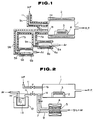
- FIG. 1 An exemplary apparatus for preparing a fluoride glass, according to the present invention, is shown in Fig. 1.
- the interior of a reaction chamber 1 is controlled to have an adjusted reduced pressure by means of an evacuation system including a rotary pump (R.P.), and has a fluorine-containing gas inlet 1 a and a vaporizable material inlet 1 b .
- the reaction chamber 1 is heated by a heater 2 surrounding the reaction chamber 1.
- a substrate 3 is placed on a heater 4 to receive thereon a depositing fluoride glass.
- Two evaporators 6 a , 6 b contain two different vaporizable materials 5 a , 5 b , and are connected to the vaporizable material inlet 1 b of the reaction chamber 1 through vaporizable material feed pipes 7 a , 7 b which meet with each other upstream of the inlet 1 b .
- Not-shown carrier gas introduction means are provided at the side opposite to the feed pipes 7 a , 7 b connected to the evaporators 6 a , 6 b so that a carrier gas, such as argon, is introduced into the reaction chamber 1.
- a carrier gas such as argon
- a fluorine-containing gas such as hydrogen fluoride gas HF is suppied from the fluorine-containing gas inlet 1 a through a fluorine-containing gas supply pipe 11 which is kept warm by a heater 9 c .
- the reaction chamber 1, the evaporators 6 a , 6 b and vaporizable gas feed pipes 7 a , 7 b may be made of aluminium, nickel, copper, iron or a nickel alloy of Ni-Cu system. It is preferrred that aluminium is used for the material of these parts, since it has excellent thermal conductivity to prevent condensation of the vaporizable materials and is also resistant to corrosion by fluorine-containing gases.
- aluminium is used to construct the reaction chamber 1, the evaporators 6 a , 6 b and voporizable gas feed pipes 7 a , 7 b , the temperature in the apparatus is uniformalized to prevent condensation of the starting materials.
- a fluoride glass having a stable composition is prepared, and hydrogen fluoride (HF) gas and fluorine (F2) gas which are effective fluorination agents for the fluorination of metal- ⁇ -diketonate complexes may be used in the apparatus.
- HF hydrogen fluoride
- F2 fluorine
- ultraviolet rays ultraviolet rays, infrared rays, far infrared rays, radio frequency induction plasma and microwave induction plasma may be used.
- the fluoride glass may be prepared while inspecting the depositing glass through a silica fiber scope.
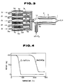
- FIG. 2 Another embodiment of the apparatus for preparaing a fluoride glass is shown in Fig. 2, wherein aluminium reaction chamber 1 is maintained at a pressure of 1333.2 Pa (10 mmHg) by means of a rotary pump (RP). Within the reaction chamber 1 a substrate 3 is placed which is a plate of CaF2. Only the substrate 3 is heated by a heater 2. The reaction chamber 1 has first and second inlet ports 1 a , 1 b respectively. A gas stream containing an organic metal compound and a metal halide is introduced through first inlet port 1 a and a stream of a fluorine-containing gas is introduced through second inlet port 1 b . In a sublimation chamber, zirconium particles 5 are reacted with a bromine gas to form ZrBr4. The reaction chamber 1 is supplied with ZrBr4 while using argon as a carrier gas through a first feed pipe 7 which is connected through a variable leak valve to the first inlet port 1 a .
- RP rotary pump
- a metal- ⁇ -diketonate complex of an organic metal compound is vaporized and fed to the reaction chamber 1 while using argon as a carrier gas.
- the first inlet port 1 a is connected to a second feed pipe 11 through a viariable leak valve.
- the second feed pipe 11 is connected to an evaporator 14 which is surrounded by a feed furnace 12, a metal-beta-diketonate complex 13 being contained in the evaporator 14.
- Argon is introduced into the mass of metal- ⁇ -diketonate complex 13 while heating the evaporator 14 so that the vaporized metal- ⁇ -diketonate complex is fed to the reaction chamber 1 via the second feed pipe 11.
- hydrogen fluoride gas HF is fed through a third feed pipe 11 and second inlet port 1 b to the reaction chamber 1.
- a variable leak valve adjusts the feed rate of HF.
- a fluoride glass is deposited on the substrate 3 in the reaction chamber 1 by the thermal decomposition of the metal- ⁇ -diketonate complex and the fluorination by the metal halide and hydrogen fluoride gas.
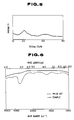
- Fig. 3 shows an appratus for preparing a preform for fluoride glass optical fibers.
- a reaction chamber 1 is evacuated by an evacuation system having a rotary pump (R.P.) so that the pressure in the reaction chamber 1 is adjustably reduced to subatmospheric pressure.
- the reaction chamber 1 is made of aluminium and has a first inlet port 1 a through which a voporizable starting mateial is introduced and a second inlet port 1 b through which a fluorine-containing gas is introduced.
- the reaction chamber 1 is maintained at 250°C, in its entirety, by a heater 2, and the pressure in the chamber 1 is maintained at a pressure of 1333.2 Pa (10 mmHg).
- a cylindrical tube 3 is disposed and made of a fluoride glass having a composition in molar ratio of 39.7ZrF4-13.3HfF4-18.0BaF2-4.0LaF3-3.0AlF3-22NaF.
- first and second inlet ports 1 a , 1 b of the reaction chamber 1 introduced are a gas stream of a metal- ⁇ -diketonate complex and a fluorine-containing gas, respectively.
- a complex Zr(HFA)4 which is a complex of hexafluoroacetylacetone (hereinafter referrred to as HFA) and zirconium was used together with a complex Ba(DHO)2 which was a complex of 2,2-dimethyl-6,6,7,7,8,8,8-heptafluoro-3,5-octanedione (hereinafter referred to as DHO)and barium.
- Hydrogen fluoride gas (HF) was used as the fluorine-containing gas.
- the interior of the reaction chamber 1 was maintained at a pressure of 1333.2 Pa (10 mmHg), and at a temperature of 205°C by using the heater 2.
- the substrate 3 was a CaF2 plate which was heated to 250°C by the heater 4.
- thermogravimetric analyses of Zr(HFA)4 and Ba(DHO)2 used as the vaporizable materials are shown in Fig. 4. Weight decrease due to vaporaization was observed at about 60°C for Zr(HFA)4 and at about 200°C for Ba(DHO)2.
- Zr(HFA)4 was maintained at 60°C in the evaporator 6 a by means of the heater 8 a and Ba(DHO)2 was maintained at 200°C in the evaporator 6 b by means of the heater 8 b .
- the voporized gases were introduced into the reaction chamber 1 while being carried by argon supplied from a carrier gas supply means (not-shown).
- the feed rate of HF was controlled by a mass flow controller.
- the feed pipes 7 a , 7 b and 11 were maintained, respectively, at 65°C, 205°C and 30°C by the heaters 9 a , 9 b and 9 c .
- Zr(HFA)4 and Ba(DHO)2 introduced in the reaction chamber 1 were converted into fluorides in the gaseous phase by the following reactions, and deposited on the substrate 3 to form a fluoride glass.
- ZrF4 and BaF2 formed by the above reactions and deposited on the substrate 3 had low mobilities on the substrate since the temperature of the substrate was maintained at a temperature lower than the transition temperatures of the fluoride glasses, and thus frozen in situ without changing positions. As a result, the non-equilibrium state was realized similarly as in the case of quenching.
- the fluoride glasses were serially deposited to prepare a glass coating or a glass bulk.
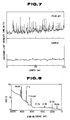
- the X-ray diffraction chart of the thus prepared glass is shown in Fig. 5, and the infrared absorption spectrum chart is shown in Fig. 6.
- Fig. 6 the infrared absorption spectrum of a fluoride glass having the same composition and prepared by a conventional melting process is shown by the broken line.
- the distribution of scattered light intensity relative to the substrate of 65ZrF4-35BaF2 glass upon launching of a He-Ne laser was measured.
- a similar scattering distribution of a fluoride glass prepared through the conventional process was determined.
- the lower chart of Fig. 7 shows the scattering distribution of the 65ZrF4-35BaF4 prepared by the process of the present invention
- the upper chart in Fig. 7 shows the scattering distribution of a glass having the same composition and prepared by the conventional process.
- the fluoride glass prepared by this Example does not show a diffraction peak due to the presence of crystal.
- the fluoride glass prepared by this Example does not show an absorption peak at about 2.9 ⁇ m due to the presence of OH group, whereas the fluoride glass prepared by the conventional process does show an absorption due to the presence of OH group.
- the fluoride glass prepared by the process of this invention is a fluoride glass in which the concentration of hydroxyl group is extremely low.
- the scattering caused by oxides is significantly decreased in the glass produced by the present invention.
- the fluoride glass prepared by the conventional process a portion of hydroxyl groups present on the surfaces of the starting materials form oxides during the melting step which cause scattering in the formed glass.
- the fluoride glass of the present invention is prepared through continuous steps including the step of vaporizing the starting materials and the step of formation of the glass, leading to reduction of oxide impurities as shown in Fig. 7.
- Fig. 8 is a spectrum chart showing the result of X-ray photoelectron spectroscopy of 65ZrF4-35BaF2 glass.
- the fluoride glass prepared by the process of the present invention is composed only of zirconium, barium and fluorine, hence signals showing the presence of C 1S and O 1S are not detected, showing that no organic materials are present. It should be appreciated from the result that the reaction between a metal- ⁇ -diketonate complex and a fluorine-containing gas can proceed at a low temperature to prevent impurities in the resultant glass.
- the metal- ⁇ -diketonate complex in the process of this invention can be vaporized at a low temperature so that the temperature throughout the overall preparation step can be maintained at a relatively low temperature, a homogenous glass can be prepared at a temperature lower than the crystallization temperature of the formed fluoride glass, even for the preparation of fluoride glasses which have low glass transition temperatures and are thermally unstable.
- fluoride glasses containing different metallic constituents may be prepared.
- the compositions of formed fluoride glasses may be easily controlled by adjusting the flow rate of argon used as the carrier gas.
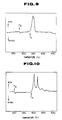
- the result of differential thermal analysis of 65ZrF4-35BaF2 glass is shown in Fig. 9.
- the glass transition temperature of the glass was 270°C and the crystallization temperature was 330°C.
- Example 1 The same apparatus was used as in Example 1 and as shown in Fig. 1. Additionaly, two evaporators similar to the evaporators 6 a , 6 b were provided and connected to the feed pipe 7 b . Similarly as in Example 1, a fluoride glass was prepared. La(DHO)3 was contained and maintained at 180°C in one of the additional evaporators, and Al(DHO)3 was contained and maintained at 90°C in the other of the additional evaporators.
- a 5.5 mm thick glass was deposited on a CaF2 substrate for a reaction time of 2 hours.
- the formed fluoride glass had a composition, in mol%, 57ZrF4-34BaF2-4.5LaF3-4.5AlF3.
- the formed fluoride glass had an improved thermal stability, compared with the glass produced in Example 1, by the addition of LaF3 and AlF3, and no change in density of scatters was observed even after subjected to a heating treatment for an hour.
- Fig. 10 The result of differential thermal analysis of the 57ZrF4-34BaF2-4.5LaF3-4.5AlF3 glass prepared by Example 2 is shown in Fig. 10.
- the glass transition temperature of the glass was 301°C, and the crystallization temperature thereof was 395°C.
- a fluoride glass was prepared as in Example 2 except that triethylaluminium Al(C2H5)3 was contained in the evaporator in place of Al(DHO)3 while using a similar apparatus to that used in Example 2.
- the evaporator containing Al(C2H5)3 was maintained at 40°C.
- a glass having a thickness of about 5.5 mm was deposited on the CaF substrate for a reaction time of 2 hours.
- the formed fluoride glass had the same composition as that of the glass prepared by Example 2, the composition of the formed glass being represented by 57ZrF4-34BaF2-4.5LaF3-4.5AlF3.
- the result of X-ray photoelectron spectroscopy revealed that no carbon was remained in the resultant glass.
- the results of infrared spectroscopy, X-ray diffraction, scattering distribution analysis and differential thermal analysis were equivalent to those of the glass prepared by Example 2, and it was revealed that an optically homogenous glass could be prepared by using organic metal compounds in lieu of ⁇ -diketonate complexes.
- glasses could be prepared by using 2,2-dimethyl-6,6,7,7,8,8,8-heptafluoro-3,5-octanedione (DHO) complexes of other rare earth metal elements, such as Ce, Pr, Nd, Pm, Sm, Eu, Gd, Tb, Dy, Ho, Er, Tm, Yb and Lu, in place of La.
- DHO 2,2-dimethyl-6,6,7,7,8,8,8-heptafluoro-3,5-octanedione
- Example 2 While using the same apparatus as used in Example 1 and shown in Fig. 1, three additional evaporators were provided and a fluoride glass was prepared through a similar procedure as described in Example 2.
- the additional evaporators contained La(DHO)3, Al(DHO)3 and Na(TMH) and were matintained, respectively, at 180°C, 60°C and 150°C.
- a glass having a thickness of about 6.5 mm was deposited on the CaF2 substrate within a reaction time of 2 hours.
- the formed glass had a composition represented by 51ZrF4-20BaF2-4.5LaF3-4.5AlF3-20NaF (in mol%).
- Example 2 By the addition of NaF to the fluoride glass of Example 2, the thermal stability of the fluoride glass was improved. The density of scatters was not changed even after the thermal treatment effected at 300°C for 5 hours. The result of differential thermal analysis showed that the glass prepared by this Example had a glass transition temperature of 260°C and a crystallization temperature of 373°C. A similar glass was prepared by using Li(TMH) in place of Na(TMH), and the formed glass containing 20 mol% of LiF was subjected to differential thermal analyssis to reaveal that it had a glass transition temperature of 252°C and a crystallization temperature of 348°C.
- La(DHO)3 was mixed, respectively, with 2,2-dimethyl-6,6,7,7,8,8,8-heptafluoro-3,5-octanedione (DHO) complexes of In, Sn, Pb, Sb, Bi, Zn, Cd, Ti. Th, Nb, Ta, Mo and Mn to prepare glasses containing 1 to 10 mol% of each of fluorides of these metals.
- the fluoride glasses showed a crystallization temperature shift by 2 to 15°C to the lower temperature side, as compared to the glass of this Example. Each of these glasses had a thickness of about 5 mm and no scattering was observed.
- a fluoride glass was prepared similarly as in Example 2 except that Hf(HFA)4 was charged in the evaporator in place of Zr(HFA)4.
- the evaporators charged with Hf(HFA)4, Ba(DHO)2, La(DHO)3 and Al(DHO)3 were maintained, respectively, at 55°c, 200°C, 180°C and 90°C.
- the feed rates were 100cc/min for Hf(HFA)4, 150 cc/min for Ba(DHO)2, 13 cc/min for La(DHO)3, 13 cc/min for 2Al(DHO)3 and 200 cc/min for HF.
- the reaction was continued for 2 hours, whereby a fluoride glass having a thickness of about 5 mm was deposited on the CaF2 substrate.
- the result of elementary anlaysis through the X-ray photoelectron analysis revealed that the formed glass had a composition in molar ratio of 57HfF4-34BaF4-4.5LaF3-4.5AlF3.
- a fluoride glass was prepared similarly as in Example 2, except that Ba(DHO)2, Ca(DHO)2, Y(DHO)3 and Al(DHO)3 were used as the starting materials and hydrogen fluoride (HF) gas was not used as the fluorine-containing gas.
- HF hydrogen fluoride
- the evaporators charged with Ba(DHO)2, Ca(DHO)2, Y(DHO)3 and Al(DHO)3 were maintained, respectively, at 200°C, 180°C, 140°C and 95°C.
- the feed rates of the metal- ⁇ -diketonate complexes were kept at 55 cc/min for Ba(DHO)2, 55 cc/min for Ca(DHO)2, 40 cc/min for Y(DHO)3 and 100 cc/min for Al(DHO)3.
- the temperature of the substrate was maintained at 380°C.
- the reaction was continued for 2 hours to obtain an about 8 mm thick fluoride glass depostited on the CaF2 glass.
- the formed fluoride glass was analysed by X-ray photoelectron analysis to find that it had a composition of 22BaF2-22CaF2-16YF3-40AlF3 (molar ratio). No residual carbon was observed. It was thus found that the ligands of ⁇ -diketonate complexes used as the starting materials were decomposed in the gaseous phase to act as the fluorinating agents, since DHO (2,2-dimethyl-6,6,7,7,8,8,8-heptafluoro-3,5-octanedione) contains fluorine atoms.
- DHO 2,2-dimethyl-6,6,7,7,8,8,8-heptafluoro-3,5-octanedione
- the glass transition temperature of the formed fluoride glass is 430°C, and the crystallization temperature thereof is 560°C. While the crystallization temperature of a fluoride glass having the same composition and prepared through the conventional melting process is 535°C, and thus the crystallization temperature of the fluoride glass obtained by the process of the present invention is higher than that of the glass prepared by the conventional process by 25°C.
- the thermal stability of the fluoride glass prepared by the present invention is improved over that of the fluoride glass prepared by the conventional melting process.
- the improvement in thermal stability is attributed to the removal of oxide impurities in the fluoride glass prepared according to the present invention, the oxide impurities being not removed in the fluoride glass prepared by the conventional melting process.
- Fluoride glasses were prepared by using Sr(DHO)2 and Ca(DHO)2 in place of Mg(DHO)2 and using MgF2 and SrF2 as the substrate in place of CaF2. About 7 mm thick glasses free of scatters were prepared.
- a fluoride glass was deposited on the substrate while using the apparatus shown in Fig. 2.
- ZrBr4 and Ba(pivaloyltrifluoromethylacetyacetone)2 (hereinafter referred to as Ba(PTA)2) were introduced through the first inlet 1 a .
- ZrBr4 was prepared by sublimating granular zirconium 5 using the heater 4 which was heated to 350°C, and reacting the sublimated zirconium with bromine gas.
- the first feed pipe 7 having the variable leak valve was connected to the container in which granular zirconium 5 was contained. Bromine gas and argon were fed to the container so that ZrBr4 was sublimated by the reaction between Zr and Br2, and the sublimated ZrBr4 was supplied through the first inlet 1 a to the reaction chamber 1 together with argon.
- the first feed pipe 7 was heated by the heater 9. The content of transition metal impurities in ZrBr4 was suppressed below 1 ppb (part per billion).
- argon acting as the carrier gas was passed through the evaporator 14 saturated with vaporized Ba(PTA)2, which was vaporized from solid Ba(PTA)2 and maintained at 120°C in the evaporator 14, and through the second feed pipe 11, the variable leak valve and the first inlet 1 a to the reaction chamber 1.
- a fluorine containing gas, hydrogen fluoride HF in this Example was supplied through the third feed pipe 11 and the second inlet 1 b to the reaction chamber 1.
- the feed rate of HF was adjusted by the variable leak valve.
- the reaction chamber 1 was maintained at 200°C and the substrate 3 was maintained at 250°C.
- ZrBr4 and Ba(PTA)2 introduced into the reaction chamber 1 were converted on the substrate 3 to ZrF4 and BaF2 as shown by the following reaction equations wherein, (g) indicates the gasesous state, (ad) indicates the adsorbed solid phase and (s) indicates the solid phase.
- a glass bulk may be prepared by continuing deposition of the fluoride glass for a sufficiently long period of time.
- the feed rates were 100 cc/min for ZrBr4, 70 cc/min for Ba(PTA)2 and 150 cc/min for HF. After reacting for 3 hours, a 6.5 mm thick fluoride glass having a composition of 60ZrF4-40BaF2 was formed.
- the result of radioactivation analysis of the formed fluoride glass revealed that the content of Fe, Cu, Ni. Co and Cr were less than 1 ppb (part per billion) which was the detection limit of the radioactivation analysis.
- fluoride glasses having various compositions were prepared and the thus prepared fluoride glasses were analysed through the fluorescent X-ray analysis. Fluoride glass blocks having varying compositions ranging within 90ZrF4-10BaF2 to 35ZrF-65BaF2 were formed. It was hard to prepare fluoride glasses having such compositions by the conventional melting or casting processes.
- the fluoride glass block prepared by Example 6 and having the composition of 60ZrF4-40BaF2 was cut into a rod shape and the surface thereof was polished to be used as a deposition substrate.
- the heating means for glass deposition was changed from heater heating to CO2 laser heating and the deposition substrate was changed from CaF2 to the glass rod, the remaining conditions and the apparatus being the same as used in Example 6, whereby a fluoride optical fiber preform was prepared.
- the glass rod had an outer diameter of 4 mm and a length of 300mm. Both ends of the glass rod were clamped by chucks, and a glass was deposited on the glass rod while the glass rod was rotated at 60 rpm and moved along its longitudinal direction at a moving speed of 10 mm/min.
- AlBr3 was introduced in addition to ZrBr4 and Ba(PTA)2 to deposite serially on the glass rod substrate a fluoride glass having a composition of 58ZrF6-37BaF2-5AlF3 which is to be used as a fluoride optical fiber preform.
- the feed rates of the starting materials were 30 cc/min for ZrBr4, 14 cc/min for Ba(PTA)2 and 2 cc/min for AlBr3.
- the temperature of the glass rod substrate was 250°C.
- the preform had a diameter of 8mm and a length of 300mm, and the relative refractive index difference between the core and the cladding was 0.7%.
- the preform was drawn into a fluoride glass optical fiber having a length of 500 meters.
- the transmission loss of the optical fiber was measured.
- the minimum loss was 8 db/km at 2.55 um. The result reveals that a long fluoride glass optical fiber having low loss can be produced by the invention.
- Ba(DHO)2 which is a complex of Ba with 2,2-dimethyl-6,6,7,7,8,8,8-heptafluoro-3,5-octanedione (DHO), Zr(HFA)4 which is a complex of Zr with hexafluoroacetylacetone (HFA), La(DHO)3 complex, Al(DHO)3 complex and Na(DHO) complex were used as starting materials.
- aluminium evaporators 9 a to 9 e charged respectively with complexes Ba(DHO)3, Zr(HFA)4, La(DHO)3, Al(DHO)3 and Na(DHO) were heated and argon gas was introduced into the respective evaporators so that vaporized starting materials were supplied through respective aluminium feed pipes 7a to 7e and the first inlet 1 a into the reaction chamber 1.
- a mixed gas of HF(95 vol%)-F2(5 vol%) was supplied through the feed pipe 4 and the second inlet 1 b into the reaction chamber 1.
- the feed rate of the metal- ⁇ -ketonate complexes and the mixed gas could be adjusted by means of mass flow controllers.
- the feed pipes 7 a to 7 e were maintained at 215°C, 65°C, 185°C, 75°C and 195°C respectively in order to prevent condensation of the respective gase contained therein.
- the metal- ⁇ -diketonate complexes introduced into the reaction chamber 1 were converted to fluorides in a form of fine glass particles due to homogeneous nucleation in the gaseous phase.
- reaction was continued for 2 hours while maintaining the feed rates of the starting materials at 50 cc/min for Ba(DHO)3, 100 cc/min for Zr(HFA)4, 10 cc/min for La(DHO)3, 7.5 cc/min for Al(DHO)3 and 7.5 cc for Na(DHO) and 15 cc/min for HF-F2 mixture gas.
- the composition of the fine glass particles was 53ZrF4-20BaF2-4LaF3-3AlF3-22NaF, and the formed product was deposited on the interior wall of the cylindrical glass tube 3.
- the composition of the cylindrical glass was 39.7ZrF4-13.3HfF4-18.0BaF2-4.0LaF3-3.0AlF3-22NaF.
- Fig. 12 shows schematically an apparatus used for collapsing a cylindrical tube having its interior wall deposited with fine glass particles.
- the temperature was set to 200°C by a heater 12, and processing was continued for 2 hours. The temperature was then raised to 280°C to collapse the tube 3 entirely, whereby a preform was obtained.
- a cylindrical tube of fluoride glass having an outer diameter of 12 mm, an inner diameter of 8 mm and a length of 150 mm was used.
- the size of the preform can be further increased.
- a cylindrical tube 3 having an outer diameter of 20mm, an inner diameter of 12 mm and a length of 300 mm was used as the substrate and deposition of fine glass particles was effected for 3 to 5 hours, followed by collapsing, whereby a large size collapsed preform was obtained.
- the temperature is maintained within the range of from 50°C to 500°C, although the temperature may be changed corresponding to the composition of the fluoride glass.
- Fluorine gas was used in this Example to remove oxide impurites absorbed on the surface of the deposited particles.
- halogen-containing gases such as gaseous compounds of fluorine or chlorine with hydrogen, carbon, nitrogen, boron, sulfur and silicon or mixture of at least two of said gases, may also be used for this purpose.
- the collapsed preform prepared by Example 9 was placed in a drawing furnace filled with an inert gas, and drawn at 285°C into a fluoride glass optical fiber.
- Fig. 13 It is apparently seen from Fig. 13 that scattering can be significantly reduced in fluoride glass produced according to the process of the present invention.
- vaporization of the starting materials for the glass and deposition or synthesis of glass particles can be effected by a single step.
- fine glass particles containing no oxide impurites can be produced.
- the oxide impurities adsorbed on the surface of the deposited mass could be removed by treatment with a fluorine-containing gas, without exposure to the outside atmosphere, whereby a preform is obtained.
- the transmission loss of the produced optical fiber was measured. The result is shown in Fig. 14.
- the minimum loss, at a wavelength of 2.55 ⁇ m, of the produced optical fiber was 0.9 dB/km which was not attainable by the conventional technology, for such a fiber length.
- Example 9 The procedure as described in Example 9 was followed so that fine particles of a fluoride glass constituting a core composition was deposited over the interior wall of a glass tube 3 constituting the cladding glass composition.
- the glass tube was then placed in a drawing furnace where it was processed at 200°C for an hour in a flowing F2 gas stream. Thereafter, the internal pressure was set to 93.33 KPa (700 Torr) by evacuating the interior of the tube from the upper end which was connected to a rotary pump.
- the drawing furnace was heated to 285°C and the glass tube was elongated simultaneously with the collapsing operation to obtain a fluoride optical fiber having a minimum transmission loss of 0.7 dB/km at 2.55 ⁇ m.
- a long fluoride glass optical fiber having a low transmission loss factor was produced in this Example, by simultaneous drawing and collapsing. Similar effects can be obtained by using Cl2, HF, HCl, BF3, SF6, SiF4, CF4 or a mixture thereof in place or in addition to F2 in the processing step prior to the drawing step.
- a fluoride optical fiber was produced as in Example 10 except that a Teflon (Trade name) fluorethylene pipe (FEP) tube was used in place of the glass tube.
- FEP fluorethylene pipe
- Hf(HFA)4 was used.
- the feed rates of respective metal- ⁇ -diketonate complexes are set out below: Zr(HFA)4 --- 87.5 cc/min Hf(HFA)4 --- 12.5 cc/min Ba(DHO)2 --- 45 cc/min La(DHO)3 --- 10 cc/min Al(DHO)3 --- 7.5 cc/min Na(DHO) --- 40 cc/min
- the flow rate of HF-F2 was 100 cc/min. Glass particles were deposited over the interior wall of the FEP (fluoroethylene pipe) tube.
- the deposited fine glass particles had a composition of 39.7ZrF4-13.3HfF2-18.0BaF2-4.0LaF2-3.0AlF3-22NaF. Thereafter, feeding of Hf(HFA)4 was stopped. Then, in order to form a core layer, feed rates of respective metal- ⁇ -diketonate complexes were adjusted to the rates as set out below: Zr(HFA)4 --- 100 cc/min Ba(DHO)2 --- 50 cc/min La(DHO)3 --- 10 cc/min Al(DHO)3 --- 7.5 cc/min Na(DHO) --- 40 cc/min
- the deposition was effected for 2 hours with the flow rates of the starting materials as set out above and the flow rate of HF-F2 was set to 100 cc/min.
- the composition of the formed glass was 53ZrF4-20BaF2-4LaF3-3AlF3-22NaF.
- the fluoride glass deposited on the interior wall of the FEP (fluoroethylene pipe) tube, the cladding layer and the core layer were drawn as described in Example 10.
- the core/cladding diameter ratio may be freely changed by varying the times for deposition of fine fluoride glass particles for the formation of core and cladding layers.
- Example 12 The process of Example 12 was followed, except that aluminium was coated by vapor deposition over the interior wall of a tube made of an oxide glass having a composition of 22B2O3-48PbO-30Tl2O3. This oxide glass tube was used in place of the FEP tube as used in Example 12.
- the cylindrical tube used as the substrate on which fine particle of fluoride glass is deposited may be a single layer or multi-layered cylindrical tube made of any of glasses, metal and organic polymers.
Landscapes
- Chemical & Material Sciences (AREA)
- Engineering & Computer Science (AREA)
- Materials Engineering (AREA)
- Chemical Kinetics & Catalysis (AREA)
- Organic Chemistry (AREA)
- Life Sciences & Earth Sciences (AREA)
- Geochemistry & Mineralogy (AREA)
- General Chemical & Material Sciences (AREA)
- Manufacturing & Machinery (AREA)
- General Life Sciences & Earth Sciences (AREA)
- Physics & Mathematics (AREA)
- Optics & Photonics (AREA)
- Glass Compositions (AREA)
Claims (15)
- Ein Verfahren zur Herstellung eines Barium enthaltenden Fluoridglases aufweisend den Schritt der Einleitung eines Gasgemisches in ein Reaktionssystem, das ein Substrat enthält zum Reagieren der Bestandteile des genannten Gasgemisches in einer gasförmigen Phase oder auf genanntem Substrat, um ein Metallfluorid zum Bilden eines Fluoridglases abzulagern, wobei das genannte Gasgemisch eine gasförmige oder verdampfbare Verbindung des metallischen Elements aufweist, das ein Bestandteil des Fluoridglases ist, wobei die gasförmige oder verdampfbare Verbindung als ein erstes Startmaterial dient, dadurch gekennzeichnet, daß desweiteren das genannte Gasgemisch
einen als zweites Startmaterial dienenden Barium-β-Diketonatkomplex enthält, der ein Komplex ist aus Barium und einem Glied aus der Gruppe 3,5-Pentadion, 2,2,6,6-Tetramethyl-3,5-Heptandion, 2,2-Dimethyl-3,5-Octandion und 1,1,1,5,5,5-Hexafluoro-2,4-Pentandion oder ein Komplex, der durch folgende allgemeine Formel (1) dargestellt wird:
- Ein Verfahren zur Herstellung eines Fluoridglases nach Anspruch 1, bei dem das genannte Gasgemisch außerdem ein fluorhaltiges Gas enthält, das als fluorisierendes Agens dient.
- Ein Verfahren zur Herstellung eines Barium enthaltenden Fluoridglases aufweisend den Schritt der Einleitung eines Gasgemisches in ein Reaktionssystem, das ein zylinderförmiges Substrat enthält zum Reagieren der Bestandteile des genannten Gasgemisches in einer gasförmigen Phase oder auf der Innenwand des genannten Substrats, um einen Überzug oder feine Partikel eines Metallfluorids zum Bilden eines Fluoridglases abzulagern, wobei das genannte Gasgemisch eine gasförmige oder verdampfbare Verbindung des metallischen Elements aufweist, das ein Bestandteil des Fluoridglases ist, wobei die gasförmige oder verdampfbare Verbindung als ein erstes Startmaterial dient, dadurch gekennzeichnet, daß desweiteren das genannte Gasgemisch
einen als zweites Startmaterial dienenden Barium-β-Diketonatkomplex enthält, der ein Komplex ist aus Barium und einem Glied aus der Gruppe 3,5-Pentadion, 2,2,6,6-Tetramethyl-3,5-Heptandion, 2,2-Dimethyl-3,5-Octandion und 1,1,1,5,5,5-Hexafluoro-2,4-Pentandion oder ein Komplex, der durch folgende allgemeine Formel (1) dargestellt wird:
wobei das Verfahren weiterhin dadurch gekennzeichnet ist, daß das zylinderförmige Substrat, in dem sich der abgelagerte Überzug oder feine Partikel eines Fluoridglases befinden, erhitzt wird, damit dieses zur Bildung einer Vorform für optische Fibern erstarrt. - Ein Verfahren zur Herstellung eines Barium enthaltenden Fluoridglases aufweisend den Schritt der Einleitung eines Gasgemisches in ein Reaktionssystem, das ein stangenförmiges Glassubstrat enthält zum Reagieren der Bestandteile des genannten Gasgemisches in einer gasförmigen Phase oder auf der Oberfläche des genannten Substrats, um eine Schicht oder feine Partikel eines Metallfluorids an der Oberfläche des genannten Substrats abzulagern, wobei das genannte Gasgemisch eine gasförmige oder verdampfbare Verbindung des metallischen Elements aufweist, das ein Bestandteil des Fluoridglases ist, wobei die gasförmige oder verdampfbare Verbindung als ein erstes Startmaterial dient, dadurch gekennzeichnet, daß desweiteren das genannte Gasgemisch
einen als zweites Startmaterial dienenden Barium-β-Diketonatkomplex enthält, der ein Komplex ist aus Barium und einem Glied aus der Gruppe 3,5-Pentadion, 2,2,6,6-Tetramethyl-3,5-Heptandion, 2,2-Dimethyl-3,5-Octandion und 1,1,1,5,5,5-Hexafluoro-2,4-Pentandion oder ein Komplex, der durch folgende allgemeine Formel (1) dargestellt wird:
wobei das Verfahren weiterhin dadurch gekennzeichnet ist, daß das stangenförmige Glassubstrat, auf dem sich eine Schicht oder abgelagerte feine Partikel eines Fluoridglases befinden, erhitzt wird, damit dieses zur Bildung einer Vorform für optische Fibern erstarrt. - Ein Verfahren nach einem der Ansprüche 1 bis 4, bei dem die genannte gasförmige oder verdampfbare Verbindung mindestens eine aus der Gruppe der Metallhalogenide, organischen Metallverbindungen und Metall-β-Diketonatkomplexe ist.
- Ein Verfahren nach Anspruch 5, bei dem die genannten Metallhalogenide Halogenide der metallischen Elemente der Ia, IIa, IIIa, IVa, Va, Ib, IIb, IIIb, IVb, Vb, VIb, VIIb und VIIIb Gruppen sind.
- Ein Verfahren nach einem der Ansprüche 1 bis 4, bei dem das genannte erste Startmaterial entweder Al(CH₃)₃ oder Al(C₂H₅)₃ ist.
- Ein Verfahren nach einem der Ansprüche 1 bis 4, bei dem das genannte β-Diketonat eines aus der Gruppe 5,5,5-Trifluoro-2,4-Pentandion, 2,2-Dimethyl-6,6,6-Trifluoro-3,5-Hexandion, 2.2.-Dimethyl-6,6,7,7,7-Pentafluoro-3,5-Heptandion und 2,2-Dimethyl-6,6,7,7,8,8,8-Heptafluoro-3,5-Octandion ist.
- Ein Verfahren nach einem der Ansprüche 1 bis 4, bei dem das genannte metallische Element, welches Bestandteil des Fluoridglases ist eines oder mehrere der Elemente aus der Gruppe Ba, Zr, Ca, Al, Na, Li, Hf, Y, La, Ce, Pr, Nd, Pm, Sm, Eu, Gd, Tb, Dy, Ho, Er, Tm, Yb, Lu, In, Sn, Pb, Sb, Bi, Zn, Cd, Ti, Th, Nb, Ta, Mo oder Mn ist.
- Ein Verfahren nach einem der Ansprüche 2, 3 und 4, bei dem das genannte fluorhaltige Gas ein Fluorgas ist oder eine gasförmige Verbindung aus Fluor mit einem oder mit mehreren der folgenden Stoffe Wasserstoff, Halogene, Kohlenstoff, Stickstoff, Bor, Silizium und Schwefel.
- Ein Verfahren nach einem der Ansprüche 1 bis 4, bei dem das genannte Substrat aus Fluoridglas, CaF₂, Metall, Oxydglas, Polymer oder mehreren Lagen davon besteht.
- Ein Verfahren nach einem der Ansprüche 1 bis 4, bei dem das genannte Fluoridglas eines der Gläser der Systeme BaF₂-ZrF₄, BaF₂-HfF₄ oder BaF₂-Alf₃ ist.
- Ein Verfahren nach Anspruch 3 oder 4, bei dem ein Hydrogenfluoridgas, das als fluorisierendes Agens dient, dem gasförmigen Strom zusätzlich zu dem genannten ersten Startmaterial und dem genannten zweiten Startmaterial hinzugefügt wird.
- Ein Verfahren nach Anspruch 3, bei dem das Fluoridglas, das an der Innenwand des zylinderförmigen Substrates abgelagert ist, in einer Umgebung von Fluor oder Chlor oder gasförmigen Verbindungen aus Fluor oder Chlor mit einem oder mit mehreren Elementen aus der Gruppe Wasserstoff, Kohlenstoff, Stickstoff, Bor, Schwefel und Silizium oder in einer Mischung aus mindestens zwei dieser genannten Gase erhitzt wird.
- Ein Verfahren nach Anspruch 3 oder 4, das außerdem den Schritt des Ziehens der genannten Vorform für optische Fibern umfaßt, um eine gezogene optische Fluoridfiber zu erstellen.
Applications Claiming Priority (8)
| Application Number | Priority Date | Filing Date | Title |
|---|---|---|---|
| JP49797/88 | 1988-03-04 | ||
| JP4979788 | 1988-03-04 | ||
| JP276007/88 | 1988-11-02 | ||
| JP27600788 | 1988-11-02 | ||
| JP1640389 | 1989-01-27 | ||
| JP16403/89 | 1989-01-27 | ||
| JP49277/89 | 1989-03-01 | ||
| JP1049277A JPH02275726A (ja) | 1988-03-04 | 1989-03-01 | フッ化物ガラス及びフッ化物ガラスを用いた光ファイバ用プリフォームの製造方法 |
Publications (3)
| Publication Number | Publication Date |
|---|---|
| EP0331483A2 EP0331483A2 (de) | 1989-09-06 |
| EP0331483A3 EP0331483A3 (en) | 1990-08-16 |
| EP0331483B1 true EP0331483B1 (de) | 1993-05-12 |
Family
ID=27456571
Family Applications (1)
| Application Number | Title | Priority Date | Filing Date |
|---|---|---|---|
| EP89302073A Expired - Lifetime EP0331483B1 (de) | 1988-03-04 | 1989-03-02 | Verfahren zur Herstellung eines Fluoridglases und Verfahren zur Herstellung einer optischen Fiber-Vorform mit diesem Glas |
Country Status (2)
| Country | Link |
|---|---|
| US (1) | US5071460A (de) |
| EP (1) | EP0331483B1 (de) |
Families Citing this family (36)
| Publication number | Priority date | Publication date | Assignee | Title |
|---|---|---|---|---|
| US5070506A (en) * | 1989-09-29 | 1991-12-03 | Hoya Corporation | Halide laser glass and laser device utilizing the glass |
| US5840897A (en) * | 1990-07-06 | 1998-11-24 | Advanced Technology Materials, Inc. | Metal complex source reagents for chemical vapor deposition |
| US5453494A (en) * | 1990-07-06 | 1995-09-26 | Advanced Technology Materials, Inc. | Metal complex source reagents for MOCVD |
| US5362328A (en) * | 1990-07-06 | 1994-11-08 | Advanced Technology Materials, Inc. | Apparatus and method for delivering reagents in vapor form to a CVD reactor, incorporating a cleaning subsystem |
| US7323581B1 (en) | 1990-07-06 | 2008-01-29 | Advanced Technology Materials, Inc. | Source reagent compositions and method for forming metal films on a substrate by chemical vapor deposition |
| US5225561A (en) * | 1990-07-06 | 1993-07-06 | Advanced Technology Materials, Inc. | Source reagent compounds for MOCVD of refractory films containing group IIA elements |
| US5204314A (en) * | 1990-07-06 | 1993-04-20 | Advanced Technology Materials, Inc. | Method for delivering an involatile reagent in vapor form to a CVD reactor |
| US5280012A (en) * | 1990-07-06 | 1994-01-18 | Advanced Technology Materials Inc. | Method of forming a superconducting oxide layer by MOCVD |
| FR2695943B1 (fr) * | 1992-09-18 | 1994-10-14 | Alsthom Cge Alcatel | Procédé de dépôt en phase vapeur d'un film en verre fluoré sur un substrat. |
| JP3665682B2 (ja) * | 1996-06-21 | 2005-06-29 | 日本山村硝子株式会社 | フッ化物薄膜の製造方法 |
| US6121164A (en) * | 1997-10-24 | 2000-09-19 | Applied Materials, Inc. | Method for forming low compressive stress fluorinated ozone/TEOS oxide film |
| US7094284B2 (en) * | 1999-10-07 | 2006-08-22 | Advanced Technology Materials, Inc. | Source reagent compositions for CVD formation of high dielectric constant and ferroelectric metal oxide thin films and method of using same |
| US20020041750A1 (en) * | 2000-06-20 | 2002-04-11 | Chacon Lisa C. | Rare earth element-doped, Bi-Sb-Al-Si glass and its use in optical amplifiers |
| US7018504B1 (en) * | 2000-09-11 | 2006-03-28 | Asm America, Inc. | Loadlock with integrated pre-clean chamber |
| DE10045264A1 (de) * | 2000-09-13 | 2002-03-21 | Zeiss Carl | Verfahren zum Aufheizen eines Werkstückes, insbesondere eines optischen Elementes |
| US6899507B2 (en) | 2002-02-08 | 2005-05-31 | Asm Japan K.K. | Semiconductor processing apparatus comprising chamber partitioned into reaction and transfer sections |
| US6935050B2 (en) | 2002-12-04 | 2005-08-30 | Corning Incorporated | Method and apparatus reducing metal impurities in optical fiber soot preforms |
| EP1586542A1 (de) * | 2004-04-05 | 2005-10-19 | Humboldt-Universität zu Berlin | Herstellungsverfahren von Fluoride Glas und dessen Verwendung |
| JP5280861B2 (ja) * | 2006-01-19 | 2013-09-04 | エーエスエム アメリカ インコーポレイテッド | 高温aldインレットマニホールド |
| US8440048B2 (en) | 2009-01-28 | 2013-05-14 | Asm America, Inc. | Load lock having secondary isolation chamber |
| US20120276291A1 (en) * | 2011-04-28 | 2012-11-01 | Bird Chester D | Methods and Apparatuses for Reducing Gelation of Glass Precursor Materials During Vaporization |
| US9574268B1 (en) | 2011-10-28 | 2017-02-21 | Asm America, Inc. | Pulsed valve manifold for atomic layer deposition |
| US9388492B2 (en) | 2011-12-27 | 2016-07-12 | Asm America, Inc. | Vapor flow control apparatus for atomic layer deposition |
| EP3083217B1 (de) | 2013-12-20 | 2019-03-27 | Novartis AG | Formen zur herstellung von kontaktlinsen |
| RU2539455C1 (ru) * | 2013-12-23 | 2015-01-20 | Федеральное Государственное Автономное Образовательное Учреждение Высшего Профессионального Образования "Дальневосточный Федеральный Университет" (Двфу) | Способ получения фторидных стекол |
| US9981436B2 (en) | 2014-12-17 | 2018-05-29 | Novartis Ag | Reusable lens molds and methods of use thereof |
| US10232574B2 (en) | 2014-12-17 | 2019-03-19 | Novartis Ag | Reusable lens molds and methods of use thereof |
| SG11201703341XA (en) | 2014-12-17 | 2017-07-28 | Novartis Ag | Reusable lens molds and methods of use thereof |
| US10662527B2 (en) | 2016-06-01 | 2020-05-26 | Asm Ip Holding B.V. | Manifolds for uniform vapor deposition |
| US11946131B2 (en) * | 2017-05-26 | 2024-04-02 | Universal Display Corporation | Sublimation cell with time stability of output vapor pressure |
| US12516414B2 (en) | 2019-03-19 | 2026-01-06 | Asm Ip Holding B.V. | Reactor manifolds |
| US11492701B2 (en) | 2019-03-19 | 2022-11-08 | Asm Ip Holding B.V. | Reactor manifolds |
| KR20210048408A (ko) | 2019-10-22 | 2021-05-03 | 에이에스엠 아이피 홀딩 비.브이. | 반도체 증착 반응기 매니폴드 |
| EP3950610A1 (de) * | 2020-08-06 | 2022-02-09 | Heraeus Quarzglas GmbH & Co. KG | Alternative fluorierungsmittel ii: fluosil und sootaufbau |
| EP3950611A1 (de) * | 2020-08-06 | 2022-02-09 | Heraeus Quarzglas GmbH & Co. KG | Alternative fluorierungsmittel zur herstellung von fluoriertem quarzglas |
| CN113461505B (zh) * | 2021-06-30 | 2022-07-26 | 湖北大学 | 一种高稳定、易挥发异核稀土螯合物及其制备方法和应用 |
Family Cites Families (9)
| Publication number | Priority date | Publication date | Assignee | Title |
|---|---|---|---|---|
| JPS57175743A (en) * | 1981-04-20 | 1982-10-28 | Nippon Telegr & Teleph Corp <Ntt> | Preparation of base material for fluoride optical fiber |
| US4378987A (en) * | 1981-10-15 | 1983-04-05 | Corning Glass Works | Low temperature method for making optical fibers |
| JPS605046A (ja) * | 1983-06-22 | 1985-01-11 | Showa Electric Wire & Cable Co Ltd | 金属コ−ト光フアイバの製造方法 |
| IT1168841B (it) * | 1983-09-15 | 1987-05-20 | Cselt Centro Studi Lab Telecom | Procedimento per la produzione di fibre ottiche a bassissima attenuazione nel medio infrarosso |
| JPS6086039A (ja) * | 1983-10-19 | 1985-05-15 | Sumitomo Electric Ind Ltd | 弗素含有シリカガラスの製造方法 |
| US4718929A (en) * | 1983-10-21 | 1988-01-12 | Corning Glass Works | Vapor phase method for making metal halide glasses |
| IT1183790B (it) * | 1985-04-03 | 1987-10-22 | Cselt Centro Studi Lab Telecom | Procedimento e apparecchiatura per la produzione di fibre ottiche per trasmissione nel medio infrarosso |
| IT1183791B (it) * | 1985-04-03 | 1987-10-22 | Cselt Centro Studi Lab Telecom | Procedimento per la produzione di vetri a base di alogenuri |
| WO1986007348A1 (en) * | 1985-06-03 | 1986-12-18 | Hughes Aircraft Company | Method for introducing dopants in optical fiber preforms |
-
1989
- 1989-03-01 US US07/317,679 patent/US5071460A/en not_active Expired - Fee Related
- 1989-03-02 EP EP89302073A patent/EP0331483B1/de not_active Expired - Lifetime
Non-Patent Citations (1)
| Title |
|---|
| R. Belcher et al., J.Inorg. Nucl. Chem. 35 (1973), 1127-43 * |
Also Published As
| Publication number | Publication date |
|---|---|
| EP0331483A2 (de) | 1989-09-06 |
| EP0331483A3 (en) | 1990-08-16 |
| US5071460A (en) | 1991-12-10 |
Similar Documents
| Publication | Publication Date | Title |
|---|---|---|
| EP0331483B1 (de) | Verfahren zur Herstellung eines Fluoridglases und Verfahren zur Herstellung einer optischen Fiber-Vorform mit diesem Glas | |
| US4718929A (en) | Vapor phase method for making metal halide glasses | |
| US3971645A (en) | Method of making compound-glass optical waveguides fabricated by a metal evaporation technique | |
| EP0529694A2 (de) | Verfahren zur thermischen Behandlung einer Glasfaservorform | |
| JPS62501699A (ja) | 多成分光ファイバ及びその製造方法 | |
| JP3339634B2 (ja) | ハロゲン化物ガラス品の調製方法 | |
| EP0814062B1 (de) | Verfahren zum Herstellen einer Dünnschicht aus Metallfluorid auf einem Substrat | |
| US5145508A (en) | Method of making fluoride glass using barium β-diketones | |
| EP0135903B1 (de) | Verfahren zur Herstellung optischer Fasern von extrem niedrigem Verlust im mittleren Infrarot | |
| US20020189527A1 (en) | Preparation of crystals | |
| US5211731A (en) | Plasma chemical vapor deposition of halide glasses | |
| Katsuyama et al. | Fabrication of high‐purity chalcogenide glasses by chemical vapor deposition | |
| US5746801A (en) | Process of producing fluoride glass | |
| USH1754H (en) | Optical glass fibers, apparatus and preparation using reactive vapor transport and deposition | |
| JPH02275726A (ja) | フッ化物ガラス及びフッ化物ガラスを用いた光ファイバ用プリフォームの製造方法 | |
| JPH06122523A (ja) | 希土類イオン含有カルコゲナイドガラスの製造方法 | |
| JP3159267B2 (ja) | フッ化物ガラスの製造方法 | |
| JPH0687617A (ja) | ゾル−ゲル法によるフッ化物ガラスの合成方法及び該方法によって得られたフッ化物ガラスから製造された光ファイバ | |
| JPH0469572B2 (de) | ||
| EP0502569B1 (de) | Verfahren zum Herstellen einer Schwermetall-Fluoridglaszusammensetzung | |
| JP3205371B2 (ja) | フッ化物薄膜の製造方法 | |
| Fujiura et al. | Chemical vapor deposition of ZrF4-based fluoride glasses | |
| Tregoat | CVD Techniques For Synthesis Of Fluoride Glass Optical Fibers | |
| JPH04305025A (ja) | フッ化物ガラスの製造方法 | |
| JP2979839B2 (ja) | フッ化物ガラス用cvd原料 |
Legal Events
| Date | Code | Title | Description |
|---|---|---|---|
| PUAI | Public reference made under article 153(3) epc to a published international application that has entered the european phase |
Free format text: ORIGINAL CODE: 0009012 |
|
| AK | Designated contracting states |
Kind code of ref document: A2 Designated state(s): FR GB |
|
| PUAL | Search report despatched |
Free format text: ORIGINAL CODE: 0009013 |
|
| AK | Designated contracting states |
Kind code of ref document: A3 Designated state(s): FR GB |
|
| 17P | Request for examination filed |
Effective date: 19900926 |
|
| 17Q | First examination report despatched |
Effective date: 19920228 |
|
| GRAA | (expected) grant |
Free format text: ORIGINAL CODE: 0009210 |
|
| AK | Designated contracting states |
Kind code of ref document: B1 Designated state(s): FR GB |
|
| ET | Fr: translation filed | ||
| REG | Reference to a national code |
Ref country code: FR Ref legal event code: CA |
|
| PGFP | Annual fee paid to national office [announced via postgrant information from national office to epo] |
Ref country code: GB Payment date: 19990304 Year of fee payment: 11 |
|
| PGFP | Annual fee paid to national office [announced via postgrant information from national office to epo] |
Ref country code: FR Payment date: 19990309 Year of fee payment: 11 |
|
| PG25 | Lapsed in a contracting state [announced via postgrant information from national office to epo] |
Ref country code: GB Free format text: LAPSE BECAUSE OF NON-PAYMENT OF DUE FEES Effective date: 20000302 |
|
| GBPC | Gb: european patent ceased through non-payment of renewal fee |
Effective date: 20000302 |
|
| PG25 | Lapsed in a contracting state [announced via postgrant information from national office to epo] |
Ref country code: FR Free format text: LAPSE BECAUSE OF NON-PAYMENT OF DUE FEES Effective date: 20001130 |
|
| REG | Reference to a national code |
Ref country code: FR Ref legal event code: ST |
|
| PLBE | No opposition filed within time limit |
Free format text: ORIGINAL CODE: 0009261 |
|
| STAA | Information on the status of an ep patent application or granted ep patent |
Free format text: STATUS: NO OPPOSITION FILED WITHIN TIME LIMIT |