EP0331402A1 - Verschweisshaspel - Google Patents
Verschweisshaspel Download PDFInfo
- Publication number
- EP0331402A1 EP0331402A1 EP89301939A EP89301939A EP0331402A1 EP 0331402 A1 EP0331402 A1 EP 0331402A1 EP 89301939 A EP89301939 A EP 89301939A EP 89301939 A EP89301939 A EP 89301939A EP 0331402 A1 EP0331402 A1 EP 0331402A1
- Authority
- EP
- European Patent Office
- Prior art keywords
- splice tray
- splice
- reel
- optic
- tray
- Prior art date
- Legal status (The legal status is an assumption and is not a legal conclusion. Google has not performed a legal analysis and makes no representation as to the accuracy of the status listed.)
- Granted
Links
Images


Classifications
-
- G—PHYSICS
- G02—OPTICS
- G02B—OPTICAL ELEMENTS, SYSTEMS OR APPARATUS
- G02B6/00—Light guides; Structural details of arrangements comprising light guides and other optical elements, e.g. couplings
- G02B6/44—Mechanical structures for providing tensile strength and external protection for fibres, e.g. optical transmission cables
- G02B6/4439—Auxiliary devices
- G02B6/444—Systems or boxes with surplus lengths
- G02B6/4453—Cassettes
- G02B6/4454—Cassettes with splices
-
- G—PHYSICS
- G02—OPTICS
- G02B—OPTICAL ELEMENTS, SYSTEMS OR APPARATUS
- G02B6/00—Light guides; Structural details of arrangements comprising light guides and other optical elements, e.g. couplings
- G02B6/44—Mechanical structures for providing tensile strength and external protection for fibres, e.g. optical transmission cables
- G02B6/4439—Auxiliary devices
- G02B6/444—Systems or boxes with surplus lengths
- G02B6/4452—Distribution frames
- G02B6/44524—Distribution frames with frame parts or auxiliary devices mounted on the frame and collectively not covering a whole width of the frame or rack
Definitions
- the present invention relates to splice trays for optic fibres.
- Splice trays are used for housing optic fibre joints. particularly in exchanges and typically comprise two spaced apart reels around which incoming optic fibres are coiled and a splice protector housing located intermediate the reels for locating and protecting an array of spliced joints formed between the ends of a multiplicity of optic fibres coiled on the reels.
- the reels serve to store spare lengths of the optic fibres and if necessary, a short length of optic fibre can be unwound from a reel if it becomes necessary to form a new joint.
- the reels also ensure that kinks or undesirable bends of small radius of curvature do not occur in the optic fibres. Such bends or kinks are undesirable because they lead to light losses and thereby impair the efficiency of communication along the fibres.
- a known splice tray manufactured by AT & T comprises two spaced-apart reel means defining respective generally annular or part-annular spaces for locating respective coiled optic fibres. and a splice protector housing for locating a spliced joint formed between such optic fibres
- At least one of said reel means is adjustable so as to enable the size of its generally annular or part-annular space to be varied.
- the coiled fibres on the reel means fit closely within the space irrespective of the thickness of the coil, which in practice will vary according to the number of optic fibres in the coil, the length of the coiled portion of each optic fibre and the thickness of the optic fibres.
- the tendency of the optic fibres to form slight bends or other deviations from a circular configuration is reduced significantly. Since an incoming optic fibre will typically form a coil of ten turns or more around its reel. even slight deviations from a smooth curvature of the optic fibre in the splice tray will lead to significant accumulative light losses. The invention enables such light losses to be reduced significantly.
- the invention is characterised by slot means formed in adjacent respective portions of the reel means, said slot means being so located as to enable an optic fibre coiled round one said reel means to extend via said slot means to the other reel means to coil round the other reel means and to join another optic fibre coiled round the first mentioned reel means at a spliced joint in said splice protector housing.
- This feature has the advantage that two optic fibres entering the splice tray from the same direction through a common aperture may be joined.
- two optic fibres entering the splice tray from the same direction in order to join two optic fibres approaching the splice tray from the same direction, one of them must be bent to enter the splice tray through another aperture to enable the fibres to be joined. Such bending is undesirable and may lead to light losses.
- the known splice tray referred to above which comprises two spaced-apart reel means defining respective spaces for locating respective coiled optic fibres. and a splice protector housing for locating a spliced joint formed between such optic fibres, also comprises means for locating another such splice tray thereon.
- the present invention is characterised in that said locating means comprises at least one detachable link member, one end of which fits to a co-operating part of the splice tray body and the other end of which is adapted to fit a co-operating part of a similar splice tray body.
- This aspect of the invention has the advantage that the detachable link member may be made the weakest item in the locating means, ensuring that if any item breaks, it is the link member which can be replaced inexpensively without affecting system operation.
- the prior art splice tray referred to above comprises a box portion having two spaced-apart reel means defining respective spaces for locating respective coiled optic fibres, a lid portion hinged to said box portion, and a splice protector housing located on said lid portion for locating a spliced joint formed between such optic fibres, said splice protector housing comprising a base and a lid mounted on said base.
- the present invention is characterised in that said base is detachable from said lid portion of the splice tray.
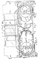
- the splice tray shown comprises a body or box portion 1 having a lid 2 attached by hinge portions 12, 13, 14 and 15 to respective hinges 121. 131, 141 and 151 of the body portion.
- the body portion 1 incorporates two compartments 1A and 1B and reels 3 and 4 are located within these compartments so as to define generally part annular spaces at their outermost ends, which receive optic fibres F1 and F2 which enter through respective apertures 16 and 17. Only about 1.5 turns of each optic fibre are shown in the two compartments. but in practice typically 24 optic fibres will enter each compartment and will each have some two metres coiled round the reel (which should not be less than 80 millimetres in diameter for a transmission wavelength of 1550 nanometres).
- a splice protector housing comprising a base 44 clipped to lid 2 by clips 8, 9, 10 and 11 and having a lid 7 hinged thereto at 49 and clipped shut by clips 48.
- Optic fibre F1 is held against lid 2 by a plate 6 which is removably clipped to the lid by clips 50, 52 and 53 and optical fibre F2 is held against lid 2 by a plate 5 which is similarly clipped to lid 2 by clips 51, 54 and 55.
- Base 44 of the splice protector housing is provided with two rows of grooves 47 to enable typically 24 spliced joints to be housed. Only one such spliced joint (indicated at X) is shown, for the sake of clarity.
- reels 3 and 4 (which are not rotatable) can be moved towards or away from each other to expand or contract the radial dimension of the part annular space at the outermost end of each compartment 1A and 1B. Accordingly, the coiled optic fibres in the outermost portion of each compartment are held closely between each reel 3 or 4 and the outer wall 132 or 133 of the compartment.
- the innermost wall portions 56 and 57 are however located some distance from the reels 4 and 3, even when the latter are located at their innermost positions.
- each optic fibre may be varied by running the optic fibre either close to the innermost wall (eg as shown in the case of optic fibre F1 which is located closely against wall 56) or maybe wound closer to the reel (as shown for example in the case of optical fibre F2).
- the optic fibre is prevented from riding up from the base of body portion 1 by inwardly extending fingers 18, 19, 20, 21, 38, 40 and 42 (compartment 1A) or 23, 24, 25, 26, 27, 39, 41, and 43 in the case of compartment 1B.
- the fingers 20, 21, 38, 40 and 42 are coplanar with the fingers 25, 26, 43, 39 and 41 and are located at a lower level than the coplanar fingers 18, 19, 22, 23, 24, and 27 in order to accommodate the components mounted on lid 2 when the latter is closed.
- optic fibre F1 enters channel 16 in the opposite direction to optic fibre F2 which enters channel 17.
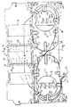
- Figure 1A shows an alternative arrangement of optic fibres which both enter channel 16. It will be seen that optic fibre F1 is conducted through slots 58 and 61 from compartment 1A to 1B before being wound round reel 3 to meet optic fibre F2 in the splice protector housing 44, 7 a similar pair of slots 59 and 60 are provided in wall portions 56 and 57 respectively to conduct an optic fibre from one compartment to the other when wound in the reverse direction. In practice, each optic fibre will be wound several times round reel 4 and optic fibre F1 may also be wound several times round reel 3 but these extra turns have been omitted for the sake of clarity.
- the reels 3 and 4 are identical and are each provided with three indentations 305, 306, 307 and 405, 406, 407 in order to avoid fouling the fingers 23, 27 and 18, 22 on removing the reels from the body 1.
- the reels 3 and 4 may be moved sufficiently far inwards to avoid fouling fingers 24 and 19 respectively.
- reel 3 has two apertures 301
- 302 and reel 4 has two similar apertures 401 and 402.
- resilient leg portions 303 and 304 extend downwardly from the innermost peripheries of these apertures and have outwardly turned portions which engage upstanding leg portions 101 and 102 of body portion 1 respectively.
- leg portions 101 and 102 are cut away in Figures 1 and 1A for the sake of clarity to reveal upwardly extending projections P(1 and 1A) which engage corrugated surfaces 1030 ( Figure 4) and thereby enable reels 3 and 4 to be shifted towards and away from one another in ratchet fashion and hold the reels 3 and 4 onto the surface of body portion 1.
- the reel 3 By squeezing leg portions 303 and 304 together, the reel 3 (and similarly reel 4) can be removed from the body portion 1 which allows replacement of a reel with (eg) a reel of a differing size or profile.
- each reel carries a projection 408 which extends into a channel 62 (reel 4) or 63 (reel 3) as shown in Figures 1A and 1B in order to locate the reels. It will also be seen from Figure 4 that the wall 133 is cut away to accommodate panel 6 attached to lid 2 ( Figure 1).
- body portion 1 carries link members 28 and 29 at the opposite ends of its front portion which carry pins 281 and 291 respectively for engagement with holes 34, 35, 36 and 37 formed in body portion 1.
- each pin 281 is in the form of a split pin.
- the tip of each split pin is expanded in order to enable each pin to clip into its aperture in body portion 1.
- two splice trays can be stacked one on top of the other with each splice tray 1′ being linked to a similar splice tray 1 beneath it by its diagonally orientated link members such as that shown at 29′.
- each link member Separation of the splice trays is prevented by a stop member 100 which engages each link member. It will be apparent that the aperture 35′ shown in Figure 3 will receive a pin of a link member diagonally attached to a further splice tray (not shown) located on lid 2′ of body portion 1′. Further attachment between the stacked splice trays is provided by clips 45 and 46 (Figure 1) and upwardly extending projections 64 and 65 ( Figure 1), of which one projection and clip are shown in detail in Figure 5. Each attachment clip 45, 46 comprises a projection 451 and carries a hook portion 452 which latches on to a similar projection formed in the body 1 of a splice tray (not shown) located on top of the body portion 1).
- the region of clip 45 round projection 1 is cut away to accommodate the hook portion (not shown) of a similar clip attached a further splice tray (not shown) located below the body portion 1 of Figure 5.
- Each projection portion such as that shown in Figure 5 at 64 locates against the interior corner of a body portion of a further splice tray (not shown) located thereon.
- the bottom splice tray in a stack may be screwed to a suitable support surface through countersunk holes 30, 31, 32 and 33 ( Figure 1) of which only hole 32 is shown in Figure 5. Engagement of two clips 45, 45′ is also illustrated in Figure 3.
- portions 144 of lid 2 are shaped to engage pins 281 and 291 of link members 28 and 29 when the latter are swung upwardly and the lid 2 is nearly closed. In this position the lid is supported by the link members 28 and 29 in a partially open position to enable the configuration of the optic fibres to be viewed before the lid 2 is completely closed. This enables inspection of the optic fibres before the lid 2 is completely shut.
- one particular modified reel 310 for use in the tray of Figure 1 is arranged to provide additional protection to very fine optic fibres, in particular of the kind sometimes called primary coated fibres.
- Primary coated fibres are of much smaller diameter than fully coated fibres and accordingly require less depth in the tray compartment.
- provision of a "standard" depth tray may be necessary if, say, primary coated fibres are to be joined to fully coated fibres. In such circumstances the distance between the tray base where the fibre is stored and the lid where joints are stored may result in an unacceptable path being taken by such a fibre.
- reel 310 carries an extension plateau 311 arranged to support the fibres towards the outer edge of the compartment to reduce the distance between the storage compartment and the lid.
- a further extension 312 slopes from the base of the storage compartment to the extension 311, the slope being arranged to prevent unacceptable curvature of fine optic fibres stored in that compartment.
- the extensions 311, 312 are shaped to extend out to the edges of the compartment in the reel area to prevent fibres falling off the side.
- the extension 311 also includes a wall 313 so that if the reel 310 is away from the side edge of the tray fibres are again retained.
- the extension 312 is arranged to terminate very slightly above the surface of the storage compartment to allow a fibre (eg F1 of Figure 1) to have a first turn at the base of the tray to enter the storage compartment prior to sloping up extension 312 and around the reel on the plateau 311.
- a fibre eg F1 of Figure 1
- reels 3 and 4 may be replaced with a reel of the kind represented by the reel 310.
Landscapes
- Physics & Mathematics (AREA)
- General Physics & Mathematics (AREA)
- Optics & Photonics (AREA)
- Mechanical Coupling Of Light Guides (AREA)
- Light Guides In General And Applications Therefor (AREA)
- Cable Accessories (AREA)
- Professional, Industrial, Or Sporting Protective Garments (AREA)
Priority Applications (1)
| Application Number | Priority Date | Filing Date | Title |
|---|---|---|---|
| AT89301939T ATE83473T1 (de) | 1988-03-02 | 1989-02-27 | Verschweisshaspel. |
Applications Claiming Priority (2)
| Application Number | Priority Date | Filing Date | Title |
|---|---|---|---|
| GB8805017 | 1988-03-02 | ||
| GB888805017A GB8805017D0 (en) | 1988-03-02 | 1988-03-02 | Splice tray |
Publications (2)
| Publication Number | Publication Date |
|---|---|
| EP0331402A1 true EP0331402A1 (de) | 1989-09-06 |
| EP0331402B1 EP0331402B1 (de) | 1992-12-16 |
Family
ID=10632744
Family Applications (1)
| Application Number | Title | Priority Date | Filing Date |
|---|---|---|---|
| EP89301939A Expired - Lifetime EP0331402B1 (de) | 1988-03-02 | 1989-02-27 | Verschweisshaspel |
Country Status (9)
| Country | Link |
|---|---|
| US (1) | US5115489A (de) |
| EP (1) | EP0331402B1 (de) |
| JP (1) | JP2904836B2 (de) |
| AT (1) | ATE83473T1 (de) |
| AU (1) | AU626842B2 (de) |
| CA (1) | CA1325715C (de) |
| DE (1) | DE68903851T2 (de) |
| GB (1) | GB8805017D0 (de) |
| WO (1) | WO1989008276A1 (de) |
Cited By (10)
| Publication number | Priority date | Publication date | Assignee | Title |
|---|---|---|---|---|
| EP0346145A3 (en) * | 1988-06-10 | 1990-07-18 | Gte Products Corporation | Emergency preterminated cable apparatus |
| US5074635A (en) * | 1990-05-21 | 1991-12-24 | Minnesota Mining And Manufacturing Company | Splice tray and method |
| US5247603A (en) * | 1992-01-24 | 1993-09-21 | Minnesota Mining And Manufacturing Company | Fiber optic connection system with exchangeable cross-connect and interconnect cards |
| EP0617304A1 (de) * | 1993-03-23 | 1994-09-28 | Reichle + De-Massari AG Elektro-Ingenieure | Kassettenanordnung zum Verbinden und Verzweigen von Lichtwellenleitern der Tele- und Datenkommunikation |
| US5363467A (en) * | 1993-05-28 | 1994-11-08 | Minnesota Mining And Manufacturing Company | Compact fiber optic housing |
| US5446822A (en) * | 1993-05-28 | 1995-08-29 | Minnesota Mining And Manufacturing Company | Connector clip for fiber optic housing |
| WO1995030165A1 (de) * | 1994-05-02 | 1995-11-09 | Felten & Guilleaume Austria Ag | Kassette |
| WO1997031281A1 (en) * | 1996-02-23 | 1997-08-28 | Leviton Manufacturing Co., Inc. | Multi-media connection housing |
| EP0926523A1 (de) * | 1997-12-18 | 1999-06-30 | REHAU AG + Co | Gehäuse für optische Komponenten |
| GB2355740B (en) * | 1999-09-23 | 2004-04-07 | Baker Hughes Inc | Protector system for fiber optic system components in subsurface applications |
Families Citing this family (32)
| Publication number | Priority date | Publication date | Assignee | Title |
|---|---|---|---|---|
| FR2687800B1 (fr) * | 1992-02-21 | 1994-04-08 | Mars Actel | Cassette adaptable de lovage et d'epissurage de fibres optiques. |
| FR2687801B1 (fr) * | 1992-02-21 | 1997-01-03 | Mars Actel | Cassette de fibres optiques. |
| NZ249802A (en) * | 1992-03-25 | 1996-08-27 | Fibernet Research Pty Ltd | Tray housing for optical fibre splices and coiled fibre |
| US5212761A (en) * | 1992-04-27 | 1993-05-18 | At&T Bell Laboratories | Fiber optic module |
| DE4302837A1 (de) * | 1993-01-28 | 1994-08-18 | Krone Ag | Gehäuse für passive optische Komponenten |
| US5353366A (en) * | 1993-10-05 | 1994-10-04 | Minnesota Mining And Manufacturing Company | Optical fiber splicing station |
| US5490229A (en) * | 1993-12-08 | 1996-02-06 | At&T Ipm Corp. | Slidably mounted optical fiber distribution tray |
| US5402515A (en) * | 1994-03-01 | 1995-03-28 | Minnesota Mining And Manufacturing Company | Fiber distribution frame system, cabinets, trays and fiber optic connector couplings |
| US5519804A (en) * | 1994-06-22 | 1996-05-21 | At&T Corp. | Universal splice tray |
| FR2733843B1 (fr) * | 1995-05-03 | 1997-05-30 | Alcatel Submarcom | Dispositif organiseur de connexion de cables a fibres optiques et boite de jonction de cables optiques |
| FR2734651B1 (fr) * | 1995-05-24 | 1997-06-20 | Alcatel Cable Interface | Boitier de raccordement de fibre optique |
| US5740300A (en) * | 1996-05-01 | 1998-04-14 | Scientific-Atlanta, Inc. | Transceiver module support apparatus with fiber management features |
| US5689606A (en) * | 1996-06-03 | 1997-11-18 | Scientific-Atlanta, Inc. | Fiber routing and retention assembly with modular fiber connector support |
| US5796908A (en) * | 1996-09-11 | 1998-08-18 | Lucent Technologies Inc. | Optical fiber organizing tray |
| US6263141B1 (en) | 1998-09-09 | 2001-07-17 | Adc Telecommunications, Inc. | Optical fiber cable management device including storage tray |
| US6215938B1 (en) | 1998-09-21 | 2001-04-10 | Adc Telecommunications, Inc. | Fiber optic cabinet and tray |
| US6353696B1 (en) * | 1999-03-19 | 2002-03-05 | Corning Cable Systems Llc | Panel for managing jumper storage |
| US6496640B1 (en) | 1999-12-16 | 2002-12-17 | Corning Cable Systems Llc | Splice closure with removable and pivotable splice trays, and associated methods |
| US6315598B1 (en) | 2000-02-01 | 2001-11-13 | Adc Telecommunications, Inc. | Outlet box with cable management spool |
| US7220144B1 (en) * | 2000-02-01 | 2007-05-22 | Adc Telecommunications, Inc. | Multimedia outlet box |
| US6612515B1 (en) | 2000-08-28 | 2003-09-02 | Adc Telecommunications, Inc. | Telecommunications cable storage spool |
| US6625374B2 (en) | 2001-03-07 | 2003-09-23 | Adc Telecommunications, Inc. | Cable storage spool |
| US6580866B2 (en) * | 2001-05-16 | 2003-06-17 | Lucent Technologies Inc. | Fiber splice holder with protected slack storage feature |
| US6819857B2 (en) | 2001-10-12 | 2004-11-16 | Adc Telecommunications, Inc. | Rotating vertical fiber tray and methods |
| US7171100B2 (en) * | 2004-11-03 | 2007-01-30 | Adc Telecommunications, Inc. | Optical fiber slack storage tray for distribution cabinet |
| US20060215980A1 (en) * | 2005-03-24 | 2006-09-28 | Yilmaz Bayazit | Splice tray arrangement |
| US7310471B2 (en) | 2005-08-25 | 2007-12-18 | Adc Telecommunications, Inc. | Stackable splice chip device |
| US7272291B2 (en) * | 2005-08-25 | 2007-09-18 | Adc Telecommunications, Inc. | Splice chip device |
| US7274852B1 (en) | 2005-12-02 | 2007-09-25 | Adc Telecommunications, Inc. | Splice tray arrangement |
| FR2929717B1 (fr) * | 2008-04-08 | 2010-09-10 | Draka Comteq France | Boitier optique |
| USD626122S1 (en) | 2009-07-07 | 2010-10-26 | Commscope, Inc. Of North Carolina | Stackable optical module enclosure |
| FR2948466B1 (fr) * | 2009-07-22 | 2011-07-15 | Nexans | Boitier d'interconnexion pour fibre optique |
Citations (6)
| Publication number | Priority date | Publication date | Assignee | Title |
|---|---|---|---|---|
| DE2621823A1 (de) * | 1976-05-17 | 1977-12-01 | Siemens Ag | Einrichtung fuer das speichern von lichtwellenleiter-ueberlaengen in kabelgarnituren |
| DE2721300A1 (de) * | 1977-05-12 | 1978-11-23 | Licentia Gmbh | Ringelement einer kassette fuer lichtleitfasern |
| US4359262A (en) * | 1980-06-30 | 1982-11-16 | Northern Telecom Limited | Tray for organizing optical fiber splices and enclosures embodying such trays |
| DE3248003A1 (de) * | 1982-12-24 | 1984-06-28 | Philips Kommunikations Industrie AG, 8500 Nürnberg | Kabelmuffe fuer lichtwellenleiter-verbindungen |
| EP0215668A2 (de) * | 1985-09-17 | 1987-03-25 | Adc Telecommunications, Inc. | Trennvorrichtung für optische Fasern |
| US4722585A (en) * | 1984-11-20 | 1988-02-02 | Mars Alcatel | Optical fiber connection support |
Family Cites Families (5)
| Publication number | Priority date | Publication date | Assignee | Title |
|---|---|---|---|---|
| US4792203A (en) * | 1985-09-17 | 1988-12-20 | Adc Telecommunications, Inc. | Optical fiber distribution apparatus |
| US4824196A (en) * | 1987-05-26 | 1989-04-25 | Minnesota Mining And Manufacturing Company | Optical fiber distribution panel |
| US4805979A (en) * | 1987-09-04 | 1989-02-21 | Minnesota Mining And Manufacturing Company | Fiber optic cable splice closure |
| US4961623A (en) * | 1989-09-05 | 1990-10-09 | Siecor Corporation | Preterminated optical cable |
| US4971421A (en) * | 1989-09-29 | 1990-11-20 | Reliance Comm/Tec Corporation | Fiber optic splice and patch enclosure |
-
1988
- 1988-03-02 GB GB888805017A patent/GB8805017D0/en active Pending
-
1989
- 1989-02-27 CA CA000592905A patent/CA1325715C/en not_active Expired - Lifetime
- 1989-02-27 JP JP1503232A patent/JP2904836B2/ja not_active Expired - Lifetime
- 1989-02-27 AU AU32197/89A patent/AU626842B2/en not_active Ceased
- 1989-02-27 US US07/548,983 patent/US5115489A/en not_active Expired - Lifetime
- 1989-02-27 EP EP89301939A patent/EP0331402B1/de not_active Expired - Lifetime
- 1989-02-27 DE DE8989301939T patent/DE68903851T2/de not_active Expired - Lifetime
- 1989-02-27 AT AT89301939T patent/ATE83473T1/de active
- 1989-02-27 WO PCT/GB1989/000202 patent/WO1989008276A1/en not_active Ceased
Patent Citations (6)
| Publication number | Priority date | Publication date | Assignee | Title |
|---|---|---|---|---|
| DE2621823A1 (de) * | 1976-05-17 | 1977-12-01 | Siemens Ag | Einrichtung fuer das speichern von lichtwellenleiter-ueberlaengen in kabelgarnituren |
| DE2721300A1 (de) * | 1977-05-12 | 1978-11-23 | Licentia Gmbh | Ringelement einer kassette fuer lichtleitfasern |
| US4359262A (en) * | 1980-06-30 | 1982-11-16 | Northern Telecom Limited | Tray for organizing optical fiber splices and enclosures embodying such trays |
| DE3248003A1 (de) * | 1982-12-24 | 1984-06-28 | Philips Kommunikations Industrie AG, 8500 Nürnberg | Kabelmuffe fuer lichtwellenleiter-verbindungen |
| US4722585A (en) * | 1984-11-20 | 1988-02-02 | Mars Alcatel | Optical fiber connection support |
| EP0215668A2 (de) * | 1985-09-17 | 1987-03-25 | Adc Telecommunications, Inc. | Trennvorrichtung für optische Fasern |
Cited By (10)
| Publication number | Priority date | Publication date | Assignee | Title |
|---|---|---|---|---|
| EP0346145A3 (en) * | 1988-06-10 | 1990-07-18 | Gte Products Corporation | Emergency preterminated cable apparatus |
| US5074635A (en) * | 1990-05-21 | 1991-12-24 | Minnesota Mining And Manufacturing Company | Splice tray and method |
| US5247603A (en) * | 1992-01-24 | 1993-09-21 | Minnesota Mining And Manufacturing Company | Fiber optic connection system with exchangeable cross-connect and interconnect cards |
| EP0617304A1 (de) * | 1993-03-23 | 1994-09-28 | Reichle + De-Massari AG Elektro-Ingenieure | Kassettenanordnung zum Verbinden und Verzweigen von Lichtwellenleitern der Tele- und Datenkommunikation |
| US5363467A (en) * | 1993-05-28 | 1994-11-08 | Minnesota Mining And Manufacturing Company | Compact fiber optic housing |
| US5446822A (en) * | 1993-05-28 | 1995-08-29 | Minnesota Mining And Manufacturing Company | Connector clip for fiber optic housing |
| WO1995030165A1 (de) * | 1994-05-02 | 1995-11-09 | Felten & Guilleaume Austria Ag | Kassette |
| WO1997031281A1 (en) * | 1996-02-23 | 1997-08-28 | Leviton Manufacturing Co., Inc. | Multi-media connection housing |
| EP0926523A1 (de) * | 1997-12-18 | 1999-06-30 | REHAU AG + Co | Gehäuse für optische Komponenten |
| GB2355740B (en) * | 1999-09-23 | 2004-04-07 | Baker Hughes Inc | Protector system for fiber optic system components in subsurface applications |
Also Published As
| Publication number | Publication date |
|---|---|
| ATE83473T1 (de) | 1993-01-15 |
| DE68903851D1 (de) | 1993-01-28 |
| CA1325715C (en) | 1994-01-04 |
| WO1989008276A1 (en) | 1989-09-08 |
| EP0331402B1 (de) | 1992-12-16 |
| JP2904836B2 (ja) | 1999-06-14 |
| AU626842B2 (en) | 1992-08-13 |
| US5115489A (en) | 1992-05-19 |
| GB8805017D0 (en) | 1988-03-30 |
| DE68903851T2 (de) | 1993-04-29 |
| JPH03503089A (ja) | 1991-07-11 |
| AU3219789A (en) | 1989-09-22 |
Similar Documents
| Publication | Publication Date | Title |
|---|---|---|
| EP0331402B1 (de) | Verschweisshaspel | |
| US6480660B1 (en) | Fiber optic cabinet and tray | |
| KR100488096B1 (ko) | 광섬유 조직장치, 광섬유 조직장치를 형성하기 위한 키트 및 광섬유 조직방법 | |
| EP3698190B1 (de) | Spleisskassette für optische fasern | |
| US4911521A (en) | Connecting box for multi-optical fiber cable | |
| US7613377B2 (en) | Hinge for fiber optic categorization and management tray | |
| EP1377862B1 (de) | Verteiler für optische fasern | |
| US6192180B1 (en) | Tray for splicing optical ribbon fibers | |
| US6424782B1 (en) | Fiber optic splice closure and method of routing optical fiber ribbons | |
| CA2041299C (en) | Splice tray and method | |
| US5206927A (en) | Cassette and cassette block for light waveguides | |
| US5142661A (en) | Fiber optic cable splice support and routing guide | |
| US11181708B2 (en) | Fiber management cassette | |
| EP0978007A1 (de) | Faseroptische verbindungsmuffe | |
| US7054535B2 (en) | Optical fiber management assembly with storage trays | |
| EP3739368B1 (de) | Spleissablage für optische fasern | |
| EP0331479A1 (de) | Faser- und Spleissverteileinrichtung | |
| KR100816420B1 (ko) | 광섬유 접속 및 점퍼여장 정리 트레이 | |
| AU2002241148A1 (en) | Optical fibre organiser |
Legal Events
| Date | Code | Title | Description |
|---|---|---|---|
| PUAI | Public reference made under article 153(3) epc to a published international application that has entered the european phase |
Free format text: ORIGINAL CODE: 0009012 |
|
| AK | Designated contracting states |
Kind code of ref document: A1 Designated state(s): AT BE CH DE ES FR GB GR IT LI LU NL SE |
|
| 17P | Request for examination filed |
Effective date: 19900208 |
|
| 17Q | First examination report despatched |
Effective date: 19910517 |
|
| GRAA | (expected) grant |
Free format text: ORIGINAL CODE: 0009210 |
|
| AK | Designated contracting states |
Kind code of ref document: B1 Designated state(s): AT BE CH DE ES FR GB GR IT LI LU NL SE |
|
| PG25 | Lapsed in a contracting state [announced via postgrant information from national office to epo] |
Ref country code: AT Effective date: 19921216 Ref country code: GR Free format text: LAPSE BECAUSE OF FAILURE TO SUBMIT A TRANSLATION OF THE DESCRIPTION OR TO PAY THE FEE WITHIN THE PRESCRIBED TIME-LIMIT Effective date: 19921216 Ref country code: ES Free format text: THE PATENT HAS BEEN ANNULLED BY A DECISION OF A NATIONAL AUTHORITY Effective date: 19921216 Ref country code: CH Effective date: 19921216 Ref country code: BE Effective date: 19921216 Ref country code: LI Effective date: 19921216 Ref country code: NL Effective date: 19921216 Ref country code: SE Effective date: 19921216 |
|
| REF | Corresponds to: |
Ref document number: 83473 Country of ref document: AT Date of ref document: 19930115 Kind code of ref document: T |
|
| ITF | It: translation for a ep patent filed | ||
| REF | Corresponds to: |
Ref document number: 68903851 Country of ref document: DE Date of ref document: 19930128 |
|
| PG25 | Lapsed in a contracting state [announced via postgrant information from national office to epo] |
Ref country code: LU Free format text: LAPSE BECAUSE OF NON-PAYMENT OF DUE FEES Effective date: 19930228 |
|
| ET | Fr: translation filed | ||
| REG | Reference to a national code |
Ref country code: CH Ref legal event code: PL |
|
| NLV1 | Nl: lapsed or annulled due to failure to fulfill the requirements of art. 29p and 29m of the patents act | ||
| PLBE | No opposition filed within time limit |
Free format text: ORIGINAL CODE: 0009261 |
|
| STAA | Information on the status of an ep patent application or granted ep patent |
Free format text: STATUS: NO OPPOSITION FILED WITHIN TIME LIMIT |
|
| 26N | No opposition filed | ||
| REG | Reference to a national code |
Ref country code: GB Ref legal event code: IF02 |
|
| PG25 | Lapsed in a contracting state [announced via postgrant information from national office to epo] |
Ref country code: IT Free format text: LAPSE BECAUSE OF NON-PAYMENT OF DUE FEES;WARNING: LAPSES OF ITALIAN PATENTS WITH EFFECTIVE DATE BEFORE 2007 MAY HAVE OCCURRED AT ANY TIME BEFORE 2007. THE CORRECT EFFECTIVE DATE MAY BE DIFFERENT FROM THE ONE RECORDED. Effective date: 20050227 |
|
| PGFP | Annual fee paid to national office [announced via postgrant information from national office to epo] |
Ref country code: GB Payment date: 20080118 Year of fee payment: 20 Ref country code: DE Payment date: 20080118 Year of fee payment: 20 |
|
| PGFP | Annual fee paid to national office [announced via postgrant information from national office to epo] |
Ref country code: FR Payment date: 20080114 Year of fee payment: 20 |
|
| REG | Reference to a national code |
Ref country code: GB Ref legal event code: 732E |
|
| REG | Reference to a national code |
Ref country code: FR Ref legal event code: TP |
|
| REG | Reference to a national code |
Ref country code: GB Ref legal event code: PE20 Expiry date: 20090226 |
|
| PG25 | Lapsed in a contracting state [announced via postgrant information from national office to epo] |
Ref country code: GB Free format text: LAPSE BECAUSE OF EXPIRATION OF PROTECTION Effective date: 20090226 |