EP0331401A2 - Pompe-dispositif à récupération d'énergie - Google Patents
Pompe-dispositif à récupération d'énergie Download PDFInfo
- Publication number
- EP0331401A2 EP0331401A2 EP89301938A EP89301938A EP0331401A2 EP 0331401 A2 EP0331401 A2 EP 0331401A2 EP 89301938 A EP89301938 A EP 89301938A EP 89301938 A EP89301938 A EP 89301938A EP 0331401 A2 EP0331401 A2 EP 0331401A2
- Authority
- EP
- European Patent Office
- Prior art keywords
- pump
- turbine
- impeller
- fluid
- cavity
- Prior art date
- Legal status (The legal status is an assumption and is not a legal conclusion. Google has not performed a legal analysis and makes no representation as to the accuracy of the status listed.)
- Granted
Links
Images


Classifications
-
- B—PERFORMING OPERATIONS; TRANSPORTING
- B01—PHYSICAL OR CHEMICAL PROCESSES OR APPARATUS IN GENERAL
- B01D—SEPARATION
- B01D61/00—Processes of separation using semi-permeable membranes, e.g. dialysis, osmosis or ultrafiltration; Apparatus, accessories or auxiliary operations specially adapted therefor
- B01D61/02—Reverse osmosis; Hyperfiltration ; Nanofiltration
- B01D61/06—Energy recovery
-
- F—MECHANICAL ENGINEERING; LIGHTING; HEATING; WEAPONS; BLASTING
- F03—MACHINES OR ENGINES FOR LIQUIDS; WIND, SPRING, OR WEIGHT MOTORS; PRODUCING MECHANICAL POWER OR A REACTIVE PROPULSIVE THRUST, NOT OTHERWISE PROVIDED FOR
- F03B—MACHINES OR ENGINES FOR LIQUIDS
- F03B3/00—Machines or engines of reaction type; Parts or details peculiar thereto
- F03B3/10—Machines or engines of reaction type; Parts or details peculiar thereto characterised by having means for functioning alternatively as pumps or turbines
- F03B3/106—Machines or engines of reaction type; Parts or details peculiar thereto characterised by having means for functioning alternatively as pumps or turbines the turbine wheel and the pumps wheel being mounted in adjacent positions on the same shaft in a single casing
-
- Y—GENERAL TAGGING OF NEW TECHNOLOGICAL DEVELOPMENTS; GENERAL TAGGING OF CROSS-SECTIONAL TECHNOLOGIES SPANNING OVER SEVERAL SECTIONS OF THE IPC; TECHNICAL SUBJECTS COVERED BY FORMER USPC CROSS-REFERENCE ART COLLECTIONS [XRACs] AND DIGESTS
- Y02—TECHNOLOGIES OR APPLICATIONS FOR MITIGATION OR ADAPTATION AGAINST CLIMATE CHANGE
- Y02E—REDUCTION OF GREENHOUSE GAS [GHG] EMISSIONS, RELATED TO ENERGY GENERATION, TRANSMISSION OR DISTRIBUTION
- Y02E10/00—Energy generation through renewable energy sources
- Y02E10/20—Hydro energy
Definitions
- the invention relates to a new and useful power recovery pump turbine to reduce the energy requirements of many industrial and liquid purification processes that involve pumping liquid or gases at high pressures.
- This invention is particularly well-suited for use in reverse osmosis processes which are used to remove salt from sea water.
- a liquid or gas is pumped at high pressure into a chamber.
- a portion of the liquid or gas is purified or otherwise processed and drawn from the chamber.
- the remainder of the high pressure gas or liquid is discharged from the chamber as reject that is disposed.
- the reject is usually at a very high pressure and this pressure must be dissipated through the use of a throttling valve or other device.
- the throttling valve reduces the pressure in the reject stream to essentially 0 psi so that all of the pressure energy in the reject stream is dissipated and provides no further benefit to the process.
- the invention is directed to an energy recovery pump turbine for use in industrial processes where a fluid is pumped at a high pressure into the process and at least a portion of the liquid is discharged from the process at a high pressure.
- a turbine is positioned to receive the high pressure discharge from the process.
- the turbine has an impeller positioned on a shaft and the discharged fluid engages the impeller and causes the impeller and shaft to rotate.
- a pump is position adjacent to the turbine to received fluid being pumped to the process.
- the pump has an impeller mounted on a shaft and the shaft of the pump is operatively connected to the shaft of the turbine. Rotation of the turbine shaft causes the impeller and the shaft of the pump to rotate whereby the pump assists in supplying the fluid under pressure to the process and to recover energy from the high pressure fluid discharged from the process.
- Also disclosed is a method for recovering energy from an industrial process where a fluid is pumped at a high pressure into the process and at least a portion of the fluid is discharged from the process at a high pressure.
- the high pressure discharged fluid is directed into the inlet of a turbine.
- the inlet of the turbine is caused to rotate by the high pressure discharged fluid.
- the turbine impeller is mounted on a rotatable shaft.
- An impeller of a pump that is mounted on the shaft is caused to rotate by the rotation of the shaft that is caused by the rotation of the turbine impeller.
- the fluid that is to be pumped to the process is directed to the inlet of the pump.
- the rotating impeller of the pump raises the pressure of the fluid supplied under high pressure to the process and recovers energy from the high pressure fluid discharged from the process.
- the invention is directed to a power recovery pump turbine that can be utilized to reduce the energy requirements of many industrial and liquid purification processes that involve pumping liquid or gases at high pressures. More particularly, the power recovery pump turbine recovers energy from the high pressure liquid or gas that is discharged from the purification process and uses this energy to pump the liquid or gas at high pressure into the purification process.
- the power recovery pump turbine of the present invention is particularly well-suited for use in a process to remove salt from sea water, called a reverse osmosis process. Accordingly, the invention will be described using the reverse osmosis process as the system where the power recovery pump turbine is utilized. It should be understood, however, that the power recovery pump turbine of the present invention can be used to reduce the energy requirements of many industrial and liquid purification processes that involve pumping liquid or gases at high pressures.
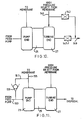
- Fig. 1 shows a typical reverse osmosis system 1 where saltwater passes through an inlet pipe 3 into a booster pump 5.
- the booster pump increases the pressure of the saltwater to about 25 pounds per square inch and pumps the saltwater through a filter 7 where suspended impurities in the saltwater can be removed. From the filter 7 the saltwater passes into feed pump 9 where the pressure of the saltwater is increased to about 1000 psi.
- the high pressure (1000 psi) saltwater is then directed into a membrane chamber 11 where salt is removed from at least a portion of the sea water.
- the membrane chamber 11 As an example, if 100 gallons per minute of saltwater is supplied to the membrane chamber 11, approximately 25 gallons per minute of purified water will be produced by the membrane chamber.
- the purified water is discharged from the membrane chamber at a low pressure through the fresh water discharge line 13.
- Approximately 75 gallons per minute of concentrated saltwater brine is discharged from the membrane chamber through the brine discharge line 15.
- the concentrated brine is discharged from the chamber at about 950 psi and this concentrated brine is called the reject.
- the high pressure reject passes through a throttle valve 17 where the pressure of the concentrated brine reject is reduced so that the reject can be discharged through a waste line 19 for disposal.
- the pressure of the reject discharged through the waste line 19 is essentially 0 psi.
- the throttle valve 17 also acts to maintain pressure in the brine discharge line 15 to maintain the proper pressure in the membrane chamber to allow at least a portion of the saltwater to be purified.
- the throttle valve lowers the pressure of the concentrated brine reject stream by approximately 950 psi.
- the hydraulic power dissipated by the throttle valve is about 42 horsepower. This is a great deal of energy that must be put into the system by the feed pump 9 and this energy is effectively lost from the system as the energy is dissipated by the throttle valve 17.
- Fig. 2 shows a reverse osmosis system where a power recovery pump turbine has been installed in the system.
- This sytem has essentially the same components as the previously described reverse osmosis system shown in Fig. 1 with the exception that a power recovery pump turbine 25 is operatively connected between the feed pump 9 and the membrane chamber 11 and the power recovery pump turbine is operatively connected to the brine discharge line 15 from the membrane chamber 11.
- the power recovery pump turbine has a turbine end 27 and a pump end 29.
- the pipe 31 from the feed pump 9 is connected to the pump inlet 33 on the pump end 29.
- the sea water passes through the pump inlet 33 through the pump end 29 and is discharged from the pump discharge 35. From the pump discharge 35 the sea water passes through pipe 37 into the membrane chamber 11.
- the portion of the sea water that is purified by the membrane chamber 11 passes from the chamber through discharge line 13.
- the concentrated brine reject passes from the membrane chamber 11 through brine discharge line 15.
- Brine discharge line 15 is operatively connected to the turbine inlet nozzle 41 on the turbine end 27 of the power recovery pump turbine 25.
- the concentrated reject passes through the turbine end 27 and is discharged from the turbine exhaust passage 43. From the turbine exhaust passage 43 the concentrated brine reject passes through waste line 45 and is disposed.
- the power recovery pump turbine unit has a center body 49, a pump end cap 51, and turbine end cap 53 and a rotor 55.
- the center body 49 and pump end cap 51 define pump impeller cavity 88 and the center body 49 and turbine end cap 53 define turbine impeller cavity 83.
- the rotor 55 consists of a pump impeller 57, turbine impeller 59 and a rotor shaft 61.
- the pump impeller 57 and the trubine impeller 59 are operatively connected to the rotor shaft 61.
- the pump impeller 57 is disposed to be located in the pump impeller cavity 88 and the turbine impeller 59 is disposed to be located in the turbine impeller cavity 83.
- the rotor shaft 61 is supported in the radial direction by a sleeve bearing 63. The rotor shaft 61 does not extend beyond the power recovery pump turbine thereby eliminating the need for external shaft seals.
- the inlet for the turbine end 27 of the power recovery pump turbine 25 is through turbine inlet nozzle 41 shown in Fig. 8.
- the turbine inlet nozzle 41 is connected to the brine discharge line 15 from the membrane chamber 11.
- the turbine exhaust passage 43 as shown in Figs. 5 and 9 connects to waste discharge line 45.
- the pump inlet 33, shown in Figs. 5 and 7 is connected to feed pipe 31 from the feed pump 9.
- the pump discharge passage 35 shown in Fig. 6 is connected to a pipe 37 that leads to the membrane chamber 11.
- a groove 67 is located in the turbine end cap 53 and forms an annular ring in the turbine end cap. The groove is in communication with the turbine impeller cavity 83 where the turbine impeller 59 is located.
- a passageway 69 passes through the turbine end cap 53 and is in communication with the groove 67.
- a passageway 73 passes through the pump end cap 51 and is in communication with the pump inlet 33.
- a conduit 75 extends between and connects the passageway 69 in the turbine end cap 53 with the passageway 73 in the pump end cap 51.
- a valve 77 is positioned in the conduit 75 adjacent to the pump end cap 51.
- An orifice plate 79 is positioned in the conduit 75 adjacent to the turbine end cap 53.
- the orifice plate 79 has a plurality of orifices located therein to regulate the flow of fluid through the conduit 75.
- the orifice plate prevents quick changes in the rate of fluid flow through the conduit 75.
- An axial clearance 81 extends between the outer periphery of the turbine impeller 59 and the turbine end cap 53.
- the axial clearance has an outer axial clearance 85 that is located on the side of the groove 67 that is spaced apart from the rotor shaft 61 and an inner axial clearance 87 that is located on the side of the groove 67 that is adjacent to the rotor shaft 61.
- the groove 67 is in communication with the axial clearance 81.
- the cross-sectional area of the annular ring formed by the groove 67 is from about 1.5 to about 2.5 times the cross-sectional area of the rotor shaft 61. In practice it has been found that the groove 67 functions well if its cross-sectional area is about 2 times the cross-sectional area of the rotor shaft 61.
- Fig. 9 Shown in Fig. 9 there is an outer seal surface 84 and an inner seal surface 86 located in the turbine end cap 53.
- the outer and inner seal surfaces are positioned adjacent the outer axial clearance 85 and inner axial clearance 87, respectively.
- Shallow grooves 89 extend radially from one side of the outer sealing surface 84 but not all the way across the outer sealing surface.
- the shallow grooves 89 from a hydrodynamic thrust bearing on the outer sealing surface. It should be understood that the shallow grooves could alternatively be position on the inner seal surface 86 to form a hydrodynamic thrust bearing.
- the portion of the outer sealing surface that contains the shallow grooves 89 produces fluid film hydrodynamic lift during rotation of the turbine impeller 59.
- the other portion of the outer sealing surface 84 provides a seal between the high pressure fluid in the groove 67 and the regions of lower pressure at the turbine exhaust passage 43 and the outer periphery of the turbine impeller 59.
- the radial width of the inner seal surface 36 should be greater than the radial width of the outer seal surface 84 due to the higher pressure differential between the groove 67 and the turbine exhaust passage 43 than between the groove 67 and the turbine inlet 41.
- the inner and outer sealing surfaces may be separately attached to the turbine end cap 53 and can be made from the same or different material than the turbine impeller 59.
- a pump impeller cavity 88 As shown in Fig. 5, on the pump end 29 of the power recovery pump turbine 25 there is a pump impeller cavity 88 and the pump impeller 57 is positioned in this cavity.
- a seal cavity 91 In the pump end cap 51 there is a seal cavity 91.
- a wear ring 93 is slideably positioned in the seal cavity 91. The wear ring is positioned so that it extends part way into the seal cavity 91.
- O-rings 95 are positioned adjacent the portion of the wear ring 93 that extends into the seal cavity 91 to provide a seal around the wear ring 93.
- a portion of the wear ring 93 extends from the seal cavity 91 and extends towards the pump impeller 57.
- This portion of the wear ring 93 has an increased cross-sectional area that acts as a stop to limit the movement of the wear ring in the seal cavity 91 in a direction away from the pump impeller 57.
- a passageway 97 extends from the seal cavity 91 to the pump inlet passageway 33.
- the portion of the wear ring 93 that extends into the seal cavity 91 terminates in a face 101.
- the end of the wear ring 93 that extends from the seal cavity 91 terminates in a seal face 103 that is adjacent to the pump impeller 57.
- the area of face 101 is approximately .4 of the area of the seal face 103.
- the wear ring 93 also has a step face 105 that faces the pump end cap 51.
- the area of the step face 105 is approximately .6 of the area of the seal face 103.
- Seal face 103 is positioned so that it is substantially parallel to the side of the pump impeller 57.
- Face 101 and step face 105 are disposed so that they are substantially parallel to seal face 103.
- the wear ring 93 is positioned so that it is free to move axially in the seal cavity 91.
- a pin 92 extends from the pump end cap 51 into the seal cavity 91 and into a cavity 94 in the wear ring 93. The pin 92 prevents the wear ring 93 from rotating but does not prevent axial movement of the wear ring in the seal cavity 91.
- sleeve bearing 63 Positioned between the pump impeller 57 and turbine impeller 59 is sleeve bearing 63. There is a chamber 111 that is positioned between the sleeve bearing 63 and the pump impeller 57. The chamber 111 is in communication with the pump impeller cavity 88. On the opposite side of the sleeve bearing 63 there is an annular space 113 that connects to the turbine impeller cavity 83. The sleeve bearing 63 is disposed around the rotor shaft 61 so that there is small seal clearance 115 between the rotor shaft 61 and the sleeve bearing 63. The seal clearance 115 provides a path of communication between the chamber 111 and the annular space 113.
- saltwater from the feed pump 9 enters the pump inlet 33 passes through the pump end 29 of the power recovery pump turbine and is directed to the membrane chamber 11.
- the salt brine reject stream from the membrane chamber 11 passes through brine discharge line 15 into the turbine inlet nozzle 41.
- the brine passes through the turbine end 27 and is discharged through the turbine exhaust passage 43.
- the turbine inlet nozzle 41 converts the high pressure brine reject flow into a high velocity flow.
- the high velocity flow brine enters the turbine impeller cavity 83 and causes the turbine impeller 59 to rotate.
- the turbine impeller 59 is mounted on rotor shaft 61 and the pump impeller 57 is also mounted on the rotor shaft 61 the rotation of the turbine impeller causes the pump impeller to rotate.
- the rotating pump impeller 57 draws saltwater from the feed pump into the pump inlet 33.
- the saltwater passes into the pump impeller cavity 88 and the rotating pump impeller 57 raises the pressure of the saltwater.
- the saltwater is then directed out through the pump discharge 35 and is directed to the membrane chamber 11. In this manner the energy in the high pressure discharge from the membrane chamber 11 can be utilized to assist in pumping saltwater into the membrane chamber.
- the feed pump 9 can deliver saltwater at approximately 600 psi to the power recovery pump turbine 25.
- the 950 psi concentrated brine reject is utilized to rotate the turbine impeller 59 which rotates the pump impeller 57 so that the saltwater entering the pump inlet 33 can be boosted from 600 psi as it enters the pump inlet to 1000 psi as it is discharged from the pump discharge 35.
- the use of the power recovery pump turbine greatly reduces the pressure increase in the saltwater required to be produced by the feed pump 9 and this significantly reduced the power requirements for the feed pump. Reducing the power requirement for the feed pump has a significant impact on the energy cost for operating the feed pump 9. At the same time the reduced feed pump discharge pressure reduces the stress on the pump and should extend the life of the feed pump.
- the concentrated saltwater brine that is discharged through the turbine exhaust passage 43 is at a very low or zero pressure so that the concentrated saltwater brine can be easily disposed of. This eliminates the need for a throttle valve to reduce the pressure of the concentrated saltwater brine that is discharged from the membrane chamber 11.
- the saltwater is delivered at a very high pressure (about 600 psi) from the feed pump 9.
- This high pressure generates a strong axial force on the components inside of the power recovery pump turbine.
- This high axial force must be accomodated through a simple reliable and low cost thrust bearing for the rotor shaft 61.
- This thrust bearing must display low drag characteristics and cannot require lubrication as the lubricants could contaminate the water passing to the membrane chamber 11.
- the power recovery pump turbine must also be able to transfer a significant portion of the hydraulic energy available in the concentrated brine reject stream from the membrane chamber 11 to justify the cost of the power recovery pump turbine.
- the pressure at the pump inlet 33 is approximately 600 psi and the pressure at the turbine exhaust passageway is essentially zero.
- This large pressure differential acts to push the rotor shaft 61 and the attached pump impeller 57 and turbine impeller 59 towards the turbine exhaust passage 43.
- the force acting on the rotor shaft 61 and the pump impeller 57 and the turbine impeller 59 can exceed 500 pounds.
- the axial thrust can be present when the rotor is revolving very slowly or is completely stationary.
- the feed pump will quickly develop its full pressure yet the rotor shaft and impellers in the power recovery pump turbine will not begin to rotate until the saltwater brine reject from the membrane chamber 11 is directed to the turbine inlet nozzle 41 to cause the turbine impeller 59 to rotate.
- the rotor shaft 61, turbine impeller 59 and pump impeller 57 will rotate slowly at the start-up due to rotor inertia.
- a fluid film thrust bearing would not be able to handle the axial thrust loads encountered during portions of the operational cycle for the power recovery pump turbine.
- a thrust balancing technique is used by the power recovery pump turbine.
- a groove 67 is located in the turbine end cap 53.
- a passageway 69 extends through the turbine end cap 53.
- the groove 67 is in comunication with the turbine impeller cavity 83.
- a passageway 73 extends through the pump end cap 51 as in communication with the pump inlet 33.
- a conduit 75 extends from the passageway 69 in the turbine end cap 53 to the passageway 73 of the pump end cap 51.
- the internal surface of the turbine end cap is machined to precisely the same contour as the side wall of the turbine impeller 59. When the feed pump is operating, the fluid pressure in the pump inlet 33 is somewhat higher than in the turbine impeller cavity 83.
- This pressure differential can cause the rotor shaft 61, the pump impeller 57 and the turbine impeller 59 to move in a direction towards the turbine end cap 53.
- the outer axial clearance 85 and the inner axial clearance 87 between the turbine impeller 59 and the turbine end cap 53 is reduced resulting in an effective sealing of the groove 67 from the turbine impeller cavity 83 and the turbine exhaust passageway 43.
- This sealing effect combined with the flow of liquid through conduit 75 causes the fluid pressure in the groove 67 to buildup and this prevents any further movement of the rotor shaft 61 towards the turbine end cap 53.
- the thrust balancing features of the power recovery pump turbine should last almost indefinitely and insure that the rotor shaft 61, the turbine impeller 59 and the pump impeller 57 are in the proper position.
- This thrust balancing technique also eliminates the need for wear rings for the turbine impeller cavity 83. Normally wear rings are used to minimize the leakage between the high pressure in the turbine impeller cavity 83 and the relatively low pressure in the turbine exhaust passageway 43.
- the extremely small axial clearance 85 between the turbine impeller cavity 83 and the turbine exhaust passageway 43 provides an effective seal and does away with the requirement for wear rings.
- the power recovery pump turbine 25 is constructed to insure adequate lubrication and cooling of the sleeve bearing 63 (as shown in Fig. 10).
- the pressure in the chamber 111 which is on the pump side of the sleeve bearing 63 is somewhat higher than the pressure in the annular space 113 which is on the turbine side of the sleeve bearing.
- This pressure differential results in the flow of liquid from the chamber 111, through the seal clearance 115 into the annular space 113.
- This flow of liquid helps to provide adquate fluid film to lubricate the bearing and also insures that frictionally generated heat is carried away from the sleeve bearing 63.
- the small seal clearance 115 effectively minimizes excessive leakage between the chamber 111 and the annular space 113.
- FIG. 5 there is shown the seal that provides a long-lasting and effective seal between the pump impeller discharge and the pump inlet.
- a wear ring 93 extends part way into the seal cavity 91 in the pump end cap 51.
- the seal cavity 91 is sealed by O-rings 95 that engage the wear ring 93.
- the wear ring 93 is free to move axially in the seal cavity 91.
- the pin 92 prevents rotation of the wearing ring 93 in the seal cavity 91.
- the seal cavity 91 is in communication with the pump inlet 33 through passageway 97. In operation the pump impeller cavity 88 becomes filled with fluid that is at a somewhat higher pressure than the fluid in the pump inlet 33.
- the average pressure acting on the seal face 103 is about halfway between the pressure in the pump impeller cavity 88 and the pump inlet 33.
- the net force acting to push the seal face 103 away from the side wall of the pump impeller 57 equals the average pressure times the area of the seal face 103.
- the force acting to push the seal face 103 towards the side wall of the pump impeller 57 equals the sum of the area of the face 101 in the seal cavity 91 times the suction pressure of the pump and the area of the step face 105 times the pressure in the pump impeller cavity 88.
- the axial seal clearance between the seal face 103 and the side wall of the impeller 57 can be maintained as less than 0.005 inches. This close clearance reduces the leakage from the impeller cavity 88 to the pump inlet 33 to a negligible value.
- Fig. 10 illustrates the use of two valves to handle extremely large changes in the flow rate into and out of the membrane chamber.
- the first valve 143 is attached to the brine discharge line 145 between the power recovery pump turbine 25 and the membrane chamber (not shown). If the pressure in the membrane chamber becomes too high due to increased flow of the concentrated saltwater brine from the membrane chamber, the first valve 143 will open.
- a second valve 147 is positioned on the disposal line 149 that extends from the turbine end 27 of the power recovery pump turbine 25. The second valve 147 restricts turbine outlet flow if the pressure in the membrane chamber becomes too low due to reduced flow of the concentrated saltwater brine that is discharged from the membrane chamber.
- the first valve 143 and second valve 147 may be manually or automatically operated.
- Fig. 11 shows a configuration for the power recovery pump turbine that can act to reduce the pressure of the saltwater that is fed from the feed pump to the membrane chamber.
- a pipe 153 directs the saltwater from the feed pump to the pump end 29 of the power recovery pump turbine 25.
- Feed pipe 155 directs the saltwater from the pump end 29 of the power recovery pump turbine 25 to the membrane chamber (not shown).
- a passageway 157 extends between the pipe 153 and the feed pipe 155 to provide an alternative path for the flow of saltwater that bypasses the power recovery pump turbine.
- a check valve 159 is positioned in the passageway 157.
- Fig. 3 shows an alternative embodiment where a power recovery turbine pump 25 is pumping in parallel with the feed pump 9.
- the saltwater leaving the filter unit 7 is split into two streams. One stream passes through the feed pump 9 which raises the water pressure to the level required by the membrane chamber 11.
- the other stream of saltwater passes through the power recovery turbine pump 25 which also raises the water pressure to the level required by the membrane chamber 11.
- the streams of saltwater discharge from the feed pump 9 and from the power recovery pump turbine 25 are combined into a single stream just prior to entering the membrane chamber 11.
- the high pressure concentrated saltwater brine that is discharged from the membrane chamber 11 is directed into the power recovery pump turbine 25 as discussed previously.
- feed pump 9 and power recovery pump turbine 25 to pump in parallel allows the use of a lower capacity feed pump as the feed pump only handles a portion of the total feed flow that is supplied to the membrane chamber 11. This reduced flow rate also reduces the power required by the feed pump 9.
- Another advantage is that if the power recovery pump turbine should fail or be removed from the reverse osmosis system, the feed pump could still provide a significant quantity of saltwater into the membrane chamber 11 at an adequate pressure to produce fresh water.
- FIG. 4 Another alternative embodiment that can be used in reverse osmosis system is shown in Fig. 4.
- the power recovery pump turbine 25 is positioned ahead of the feed pump 9 and filter 7.
- the power recovery pump turbine eliminates the booster pump shown in Fig. 2.
- the power recovery pump turbine acts as previously described to increase the pressure of the saltwater that is to be purified.
- the pressure is increased before the saltwater passes through the filter and is fed into the feed pump 9.
- the same general benefits are derived as the feed pump 9 does not have to provide as much of an increase in the pressure of the saltwater and this greatly reduces the power requirements for the feed pump and can extend the life of the feed pump.
- energy is recovered from the high pressure concentrated saltwater brine that is discharged from the membrane channel 11. This energy is effectively recaptured and utilized by the power recovery pump turbine 25 to produce the overall energy requirements of the reverse osmosis system.
Landscapes
- Engineering & Computer Science (AREA)
- Chemical & Material Sciences (AREA)
- Water Supply & Treatment (AREA)
- Combustion & Propulsion (AREA)
- Mechanical Engineering (AREA)
- General Engineering & Computer Science (AREA)
- Nanotechnology (AREA)
- Chemical Kinetics & Catalysis (AREA)
- Structures Of Non-Positive Displacement Pumps (AREA)
- Control Of Non-Positive-Displacement Pumps (AREA)
- Separation Using Semi-Permeable Membranes (AREA)
Applications Claiming Priority (2)
| Application Number | Priority Date | Filing Date | Title |
|---|---|---|---|
| US16067988A | 1988-02-26 | 1988-02-26 | |
| US160679 | 1988-02-26 |
Publications (3)
| Publication Number | Publication Date |
|---|---|
| EP0331401A2 true EP0331401A2 (fr) | 1989-09-06 |
| EP0331401A3 EP0331401A3 (en) | 1990-06-13 |
| EP0331401B1 EP0331401B1 (fr) | 1994-08-17 |
Family
ID=22577947
Family Applications (1)
| Application Number | Title | Priority Date | Filing Date |
|---|---|---|---|
| EP89301938A Expired - Lifetime EP0331401B1 (fr) | 1988-02-26 | 1989-02-27 | Pompe-dispositif à récupération d'énergie |
Country Status (4)
| Country | Link |
|---|---|
| EP (1) | EP0331401B1 (fr) |
| JP (1) | JP2934252B2 (fr) |
| CA (1) | CA1329730C (fr) |
| DE (1) | DE68917497D1 (fr) |
Cited By (6)
| Publication number | Priority date | Publication date | Assignee | Title |
|---|---|---|---|---|
| EP0636787A1 (fr) * | 1993-07-28 | 1995-02-01 | KSB Aktiengesellschaft | Pompe-turbine unidirectionnelle |
| CN102966567A (zh) * | 2012-10-19 | 2013-03-13 | 福建省尤溪长波水力机械有限公司 | 抽水、发电两用的水轮泵 |
| CN103370531A (zh) * | 2010-12-07 | 2013-10-23 | 福伊特专利公司 | 泵涡轮设备 |
| CN104806422A (zh) * | 2015-03-04 | 2015-07-29 | 王明优 | 一种海水发电设备用双管液压泵 |
| US10041367B2 (en) | 2013-12-12 | 2018-08-07 | General Electric Company | Axially faced seal system |
| WO2022252006A1 (fr) * | 2021-05-31 | 2022-12-08 | 3M Innovative Properties Company | Unité d'amplification et système de filtration à osmose inverse |
Families Citing this family (4)
| Publication number | Priority date | Publication date | Assignee | Title |
|---|---|---|---|---|
| DE102006022555B4 (de) * | 2006-05-15 | 2010-12-16 | Rieter Automatik Gmbh | Vorrichtung und Verfahren zur Erzeugung eines Granulats aus einer Kunststoffschmelze |
| JP4870648B2 (ja) * | 2007-10-25 | 2012-02-08 | 株式会社荏原製作所 | 動力回収システム |
| AU2010354672B2 (en) * | 2010-05-31 | 2014-04-10 | Kabushiki Kaisha Toshiba | Power recovery device of liquid treatment apparatus |
| EP4104916B1 (fr) * | 2021-06-15 | 2024-09-25 | Danfoss A/S | Agencement d'osmose inverse |
Citations (10)
| Publication number | Priority date | Publication date | Assignee | Title |
|---|---|---|---|---|
| US2652228A (en) * | 1950-01-11 | 1953-09-15 | Carrier Corp | Bearing construction |
| US3180832A (en) * | 1963-03-07 | 1965-04-27 | Exxon Research Engineering Co | Oil compositions containing anti-wear additives |
| US4105571A (en) * | 1977-08-22 | 1978-08-08 | Exxon Research & Engineering Co. | Lubricant composition |
| EP0024146A1 (fr) * | 1979-08-13 | 1981-02-25 | Exxon Research And Engineering Company | Compositions lubrifiantes |
| EP0039998A1 (fr) * | 1980-05-08 | 1981-11-18 | Exxon Research And Engineering Company | Composition d'huile lubrifiante contenant un additif capable de réduire la formation de dépôts |
| US4410429A (en) * | 1980-07-07 | 1983-10-18 | Foster-Miller Associates | Linear pocket energy exchange device |
| DE3510160A1 (de) * | 1985-03-21 | 1986-09-25 | Hellmut 7923 Königsbronn Weinrich | Druckwasserversorgungsanlage zur wasserentsalzung |
| US4664822A (en) * | 1985-12-02 | 1987-05-12 | Amoco Corporation | Metal-containing lubricant compositions |
| EP0225580A2 (fr) * | 1985-12-02 | 1987-06-16 | Ethyl Corporation | Compositions lubrifiantes contenant du métal |
| EP0241363A1 (fr) * | 1986-04-08 | 1987-10-14 | Commissariat A L'energie Atomique | Dérivés de nucléosides et leur utilisation pour la synthèse d'oligonucléotides |
Family Cites Families (2)
| Publication number | Priority date | Publication date | Assignee | Title |
|---|---|---|---|---|
| JPS60159301A (ja) * | 1984-01-27 | 1985-08-20 | Mitsubishi Heavy Ind Ltd | ポンプ及び動力回収タ−ビン装置 |
| JPS6291693A (ja) * | 1985-10-16 | 1987-04-27 | Nikkiso Co Ltd | 動力回収形キヤンドモ−タポンプ |
-
1989
- 1989-02-24 CA CA000591979A patent/CA1329730C/fr not_active Expired - Fee Related
- 1989-02-27 JP JP1043403A patent/JP2934252B2/ja not_active Expired - Fee Related
- 1989-02-27 DE DE68917497T patent/DE68917497D1/de not_active Expired - Lifetime
- 1989-02-27 EP EP89301938A patent/EP0331401B1/fr not_active Expired - Lifetime
Patent Citations (10)
| Publication number | Priority date | Publication date | Assignee | Title |
|---|---|---|---|---|
| US2652228A (en) * | 1950-01-11 | 1953-09-15 | Carrier Corp | Bearing construction |
| US3180832A (en) * | 1963-03-07 | 1965-04-27 | Exxon Research Engineering Co | Oil compositions containing anti-wear additives |
| US4105571A (en) * | 1977-08-22 | 1978-08-08 | Exxon Research & Engineering Co. | Lubricant composition |
| EP0024146A1 (fr) * | 1979-08-13 | 1981-02-25 | Exxon Research And Engineering Company | Compositions lubrifiantes |
| EP0039998A1 (fr) * | 1980-05-08 | 1981-11-18 | Exxon Research And Engineering Company | Composition d'huile lubrifiante contenant un additif capable de réduire la formation de dépôts |
| US4410429A (en) * | 1980-07-07 | 1983-10-18 | Foster-Miller Associates | Linear pocket energy exchange device |
| DE3510160A1 (de) * | 1985-03-21 | 1986-09-25 | Hellmut 7923 Königsbronn Weinrich | Druckwasserversorgungsanlage zur wasserentsalzung |
| US4664822A (en) * | 1985-12-02 | 1987-05-12 | Amoco Corporation | Metal-containing lubricant compositions |
| EP0225580A2 (fr) * | 1985-12-02 | 1987-06-16 | Ethyl Corporation | Compositions lubrifiantes contenant du métal |
| EP0241363A1 (fr) * | 1986-04-08 | 1987-10-14 | Commissariat A L'energie Atomique | Dérivés de nucléosides et leur utilisation pour la synthèse d'oligonucléotides |
Cited By (6)
| Publication number | Priority date | Publication date | Assignee | Title |
|---|---|---|---|---|
| EP0636787A1 (fr) * | 1993-07-28 | 1995-02-01 | KSB Aktiengesellschaft | Pompe-turbine unidirectionnelle |
| CN103370531A (zh) * | 2010-12-07 | 2013-10-23 | 福伊特专利公司 | 泵涡轮设备 |
| CN102966567A (zh) * | 2012-10-19 | 2013-03-13 | 福建省尤溪长波水力机械有限公司 | 抽水、发电两用的水轮泵 |
| US10041367B2 (en) | 2013-12-12 | 2018-08-07 | General Electric Company | Axially faced seal system |
| CN104806422A (zh) * | 2015-03-04 | 2015-07-29 | 王明优 | 一种海水发电设备用双管液压泵 |
| WO2022252006A1 (fr) * | 2021-05-31 | 2022-12-08 | 3M Innovative Properties Company | Unité d'amplification et système de filtration à osmose inverse |
Also Published As
| Publication number | Publication date |
|---|---|
| EP0331401B1 (fr) | 1994-08-17 |
| DE68917497D1 (de) | 1994-09-22 |
| EP0331401A3 (en) | 1990-06-13 |
| JP2934252B2 (ja) | 1999-08-16 |
| JPH01294903A (ja) | 1989-11-28 |
| CA1329730C (fr) | 1994-05-24 |
Similar Documents
| Publication | Publication Date | Title |
|---|---|---|
| US5049045A (en) | Power recovery turbine pump | |
| US4983305A (en) | Power recovery pump turbine | |
| US4966708A (en) | Power recovery pump turbine | |
| CN1023618C (zh) | 平衡活塞和密封装置 | |
| US4472107A (en) | Rotary fluid handling machine having reduced fluid leakage | |
| US5129795A (en) | Motor driven pump | |
| AU766706B2 (en) | A screw compressor injected with water | |
| EP0331401A2 (fr) | Pompe-dispositif à récupération d'énergie | |
| US4067665A (en) | Turbine booster pump system | |
| US5045711A (en) | Turboexpander-generator | |
| WO2001035003A1 (fr) | Dispositif de transmission de puissance | |
| US3998052A (en) | Hydraulic turning arrangement for a turbine rotor | |
| RU2179653C2 (ru) | Уплотняющая система гидравлической машины | |
| HU207380B (en) | Bearing arrangement with bearing lubricant intaking device | |
| RU2177080C2 (ru) | Гидравлическая машина | |
| CN213331547U (zh) | 一种液压潜水螺旋离心泵 | |
| EP0959254B1 (fr) | Pompe centrifuge avec joint d'étanchéité radial | |
| CN1011731B (zh) | 用于旋转轴,特别用于船舶推进系统的尾轴管密封装置 | |
| CN101180466B (zh) | 用于动力传送设备的限转矩润滑油泵 | |
| RU2662786C1 (ru) | Комплекс для создания контура охлаждения и смазки радиально-осевого подшипника | |
| CN216554619U (zh) | 海水淡化高压泵 | |
| CN111637060B (zh) | 一种液压潜水螺旋离心泵 | |
| US20230184255A1 (en) | Bearing assemblies, apparatuses, devices, systems, and methods including bearings | |
| EP3857072B1 (fr) | Pompe à plusieurs étages, à optimisation de poussée axiale | |
| JPH1089283A (ja) | 多段ポンプ |
Legal Events
| Date | Code | Title | Description |
|---|---|---|---|
| PUAI | Public reference made under article 153(3) epc to a published international application that has entered the european phase |
Free format text: ORIGINAL CODE: 0009012 |
|
| AK | Designated contracting states |
Kind code of ref document: A2 Designated state(s): BE DE FR GB IT SE |
|
| PUAL | Search report despatched |
Free format text: ORIGINAL CODE: 0009013 |
|
| AK | Designated contracting states |
Kind code of ref document: A3 Designated state(s): BE DE FR GB IT SE |
|
| 17P | Request for examination filed |
Effective date: 19900808 |
|
| 17Q | First examination report despatched |
Effective date: 19910709 |
|
| GRAA | (expected) grant |
Free format text: ORIGINAL CODE: 0009210 |
|
| AK | Designated contracting states |
Kind code of ref document: B1 Designated state(s): BE DE FR GB IT SE |
|
| PG25 | Lapsed in a contracting state [announced via postgrant information from national office to epo] |
Ref country code: IT Free format text: LAPSE BECAUSE OF FAILURE TO SUBMIT A TRANSLATION OF THE DESCRIPTION OR TO PAY THE FEE WITHIN THE PRE;WARNING: LAPSES OF ITALIAN PATENTS WITH EFFECTIVE DATE BEFORE 2007 MAY HAVE OCCURRED AT ANY TIME BEFORE 2007. THE CORRECT EFFECTIVE DATE MAY BE DIFFERENT FROM THE ONE RECORDED.SCRIBED TIME-LIMIT Effective date: 19940817 Ref country code: FR Effective date: 19940817 Ref country code: BE Effective date: 19940817 |
|
| REF | Corresponds to: |
Ref document number: 68917497 Country of ref document: DE Date of ref document: 19940922 |
|
| PG25 | Lapsed in a contracting state [announced via postgrant information from national office to epo] |
Ref country code: SE Effective date: 19941117 |
|
| PG25 | Lapsed in a contracting state [announced via postgrant information from national office to epo] |
Ref country code: DE Effective date: 19941118 |
|
| EN | Fr: translation not filed | ||
| PLBE | No opposition filed within time limit |
Free format text: ORIGINAL CODE: 0009261 |
|
| STAA | Information on the status of an ep patent application or granted ep patent |
Free format text: STATUS: NO OPPOSITION FILED WITHIN TIME LIMIT |
|
| 26N | No opposition filed | ||
| REG | Reference to a national code |
Ref country code: GB Ref legal event code: IF02 |
|
| PGFP | Annual fee paid to national office [announced via postgrant information from national office to epo] |
Ref country code: GB Payment date: 20030219 Year of fee payment: 15 |
|
| PG25 | Lapsed in a contracting state [announced via postgrant information from national office to epo] |
Ref country code: GB Free format text: LAPSE BECAUSE OF NON-PAYMENT OF DUE FEES Effective date: 20040227 |
|
| GBPC | Gb: european patent ceased through non-payment of renewal fee |