EP0331064B1 - Dispositif d'illumination pour illuminer des enceintes fermées - Google Patents
Dispositif d'illumination pour illuminer des enceintes fermées Download PDFInfo
- Publication number
- EP0331064B1 EP0331064B1 EP19890103373 EP89103373A EP0331064B1 EP 0331064 B1 EP0331064 B1 EP 0331064B1 EP 19890103373 EP19890103373 EP 19890103373 EP 89103373 A EP89103373 A EP 89103373A EP 0331064 B1 EP0331064 B1 EP 0331064B1
- Authority
- EP
- European Patent Office
- Prior art keywords
- lighting device
- light
- light source
- environment
- glass rod
- Prior art date
- Legal status (The legal status is an assumption and is not a legal conclusion. Google has not performed a legal analysis and makes no representation as to the accuracy of the status listed.)
- Expired - Lifetime
Links
- 239000011521 glass Substances 0.000 claims description 29
- 239000002184 metal Substances 0.000 claims description 4
- 125000006850 spacer group Chemical group 0.000 claims description 2
- 238000005253 cladding Methods 0.000 description 7
- 230000008878 coupling Effects 0.000 description 5
- 238000010168 coupling process Methods 0.000 description 5
- 238000005859 coupling reaction Methods 0.000 description 5
- 238000007689 inspection Methods 0.000 description 5
- 238000006073 displacement reaction Methods 0.000 description 3
- 238000012423 maintenance Methods 0.000 description 3
- 239000000463 material Substances 0.000 description 2
- 230000005855 radiation Effects 0.000 description 2
- 241000723353 Chrysanthemum Species 0.000 description 1
- 235000005633 Chrysanthemum balsamita Nutrition 0.000 description 1
- 241000196324 Embryophyta Species 0.000 description 1
- VYPSYNLAJGMNEJ-UHFFFAOYSA-N Silicium dioxide Chemical compound O=[Si]=O VYPSYNLAJGMNEJ-UHFFFAOYSA-N 0.000 description 1
- 238000010521 absorption reaction Methods 0.000 description 1
- 239000002131 composite material Substances 0.000 description 1
- 238000009792 diffusion process Methods 0.000 description 1
- 239000005350 fused silica glass Substances 0.000 description 1
- 230000004927 fusion Effects 0.000 description 1
- 238000009434 installation Methods 0.000 description 1
- 238000004519 manufacturing process Methods 0.000 description 1
- 238000000034 method Methods 0.000 description 1
- 230000003287 optical effect Effects 0.000 description 1
- 230000000149 penetrating effect Effects 0.000 description 1
- 230000035515 penetration Effects 0.000 description 1
- 230000002093 peripheral effect Effects 0.000 description 1
- 238000011112 process operation Methods 0.000 description 1
- 230000002285 radioactive effect Effects 0.000 description 1
- 229910052594 sapphire Inorganic materials 0.000 description 1
- 239000010980 sapphire Substances 0.000 description 1
- 238000000926 separation method Methods 0.000 description 1
- 231100000331 toxic Toxicity 0.000 description 1
- 230000002588 toxic effect Effects 0.000 description 1
Images


Classifications
-
- G—PHYSICS
- G02—OPTICS
- G02B—OPTICAL ELEMENTS, SYSTEMS OR APPARATUS
- G02B6/00—Light guides; Structural details of arrangements comprising light guides and other optical elements, e.g. couplings
- G02B6/0001—Light guides; Structural details of arrangements comprising light guides and other optical elements, e.g. couplings specially adapted for lighting devices or systems
- G02B6/0005—Light guides; Structural details of arrangements comprising light guides and other optical elements, e.g. couplings specially adapted for lighting devices or systems the light guides being of the fibre type
-
- G—PHYSICS
- G21—NUCLEAR PHYSICS; NUCLEAR ENGINEERING
- G21F—PROTECTION AGAINST X-RADIATION, GAMMA RADIATION, CORPUSCULAR RADIATION OR PARTICLE BOMBARDMENT; TREATING RADIOACTIVELY CONTAMINATED MATERIAL; DECONTAMINATION ARRANGEMENTS THEREFOR
- G21F7/00—Shielded cells or rooms
- G21F7/04—Shielded glove-boxes
- G21F7/043—Lighting
-
- F—MECHANICAL ENGINEERING; LIGHTING; HEATING; WEAPONS; BLASTING
- F21—LIGHTING
- F21W—INDEXING SCHEME ASSOCIATED WITH SUBCLASSES F21K, F21L, F21S and F21V, RELATING TO USES OR APPLICATIONS OF LIGHTING DEVICES OR SYSTEMS
- F21W2131/00—Use or application of lighting devices or systems not provided for in codes F21W2102/00-F21W2121/00
- F21W2131/40—Lighting for industrial, commercial, recreational or military use
- F21W2131/411—Lighting for industrial, commercial, recreational or military use for inspection of the interior of hollow structures, e.g. vessels, tubes
Definitions
- the invention relates to a lighting device as defined in the preamble of claim 1.
- Hot cells in nuclear plants are good examples because of the radioactive and toxic materials tested therein and because of the high temperatures and the often sophisticated peripheral structures. Most delicate are those cases where the installation of remotely controlled inspection devices and lighting devices associated thereto within the environment is forbidden or extremely undesirable. Such a case is for instance the vacuum plasma chamber of a nuclear fusion test facility such as the circular vessel of a TOKAMAK, the internal geometry of which must not be altered by any stationary structures.
- the design of inspection and lighting devices for this type of application must take into account two specific requirements:
- the present invention refers to a lighting device for the use in hostile, closed environments, which offers a reliable solution to said problems.
- the lighting device for illuminating a closed environment comprising a light source and at least one glass rod which is optically and mechanically coupled thereto and extends through an enclosure wall, and which is provided with a light diffusor at its free end
- the light source and at least one glass rod constitute a mobile unit
- at least one gastight window is interposed between the light source and the glass rod
- an access tube passing straight through the enclosure wall and opening into the environment receives and guides the mobile unit slidingly lodged therein
- at least one cylindrical bellow is coupled in a gastight manner to the access tube as well as to the rim of one of the windows, and that the bellow is dimensioned such as to allow the diffusor to penetrate into the environment and to be retracted therefrom.
- the lighting device is located entirely outside the environment to be inspected, and the only movement executed with the device is a longitudinal displacement through the access tube over a relatively short distance.
- the components subject to maintenance and exposed to failure are accessible from outside the environment.
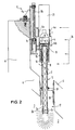
- the lighting device comprises a light source 1, e.g. a commercial metal vapour arc lamp of some hundred Watts associated with a reflector and a vertical glass rod 2, surrounded by a metal cladding tube 2a.
- the rod has at its free end a roughened surface which acts as a diffuser 3 for projecting light into the environment 7.
- the light source and the glass rod (light guide) are rigidly coupled through a sleeve 4.
- the light source projects focussed light directly into the glass rod, the angle of the light cone being chosen such that a maximum amount of light is injected into the glass rod.
- the high efficiency of this coupling is also due to the high transparency of the used materials (sapphire glass window and high purity fused silica) and the narrow focussing point of the lamp light.
- Two windows 10, 11 are interposed between the light source 1 and the glass rod 2 and constitute a gastight separation between the atmosphere in the environment 7 to be illuminated and the ambient atmosphere.
- the windows are mounted in a twin-tubular connection member 13 which is locked to the sleeve 4 and tightly connected at its lower rim to the cladding tube 2a.
- the lamp 1, the rod 2 with its cladding tube 2a and its windows 10 and 11 together with the connection member 13 and the coupling sleeve 4 constitute a rigid but mobile unit which is received by and guided in an access tube 5 passing straight through the enclosure wall 6 and ending in the environment 7 to be illuminated.
- the lower portion of the mobile unit including the glass rod in its cladding tube is slidingly lodged in the access tube 5.
- the cladding tube 2a of the glass rod abuts against a shoulder 2b of the rod and is provided with clamping fingers 2c gripping the glass rod below said shoulder. By releasing the fingers, it is possible to extract the glass rod from the cladding tube (and thus form the lighting system), especially for exchange or repair purposes.
- the direction taken by the light emitted by the lamp 1 in the light guide 2 is visualized by the dotted lines 8 in figure 2.
- the light trapped in the guide is reflected internally at the wall of the glass rod and it leaves the rod through the diffusor 3.
- the entire surface of the rod end is roughened, so that the light is shed over 360°.
- the displacement of the lighting device in the access tube 5, which is only longitudinal in both directions, is performed by the drive device 9.
- It comprises a stationary structure 9a, bolted to the enclosure wall 6 (upper part), a spindle shaft 9b rotated by a motor (not shown) and a nut 9c engaging the spindle and connected to a bracket 9d of the drive device.
- the bracket is hinged to the sleeve 4.
- the spindle shaft 9b is mounted in parallel to the axis of the lighting device.
- the windows 10 and 11 are coupled via their twin-tubular connection member 13 by means of bellows 14 and 15 to the access tube 5.
- the provision of two windows and two bellows is made for safety reasons in order to maintain tightness if one window is broken or one bellow leaks.
- the bellows are expanded when the lighting device is in its off-duty position (figure 1) and they are contracted when the device is in its operative position (figure 2).
- the length of the bellows in the expanded position, the penetration depth of the glass rod into the environment 7 to be illuminated and the travelling path of the nut 9c on the spindle shaft 9b are adjusted to each other and determine the course of the lighting device.
- the access tube 5 is laid through a test channel 17 in the enclosure wall 6 and at its lower end, it is gastightly secured to this enclosure wall 6.
- an adapter sleeve 18 is provided for bridging the gap.
- the sleeve is connected with one end to the test channel 17 and with the other end to a short additional bellow 19, which in turn is connected to the access tube 5 in a gastight manner.
- This bellow is only provided for taking over slight movements of the access tube due for instance to thermal expansions or to manufacturing tolerances.
- the free space within the adapter sleeve can be used for mounting a flap valve (not shown) actuated by a weight for closing the opening of the access tube when the diffusor 3 is entirely retracted.
- Discoupling of the snap fingers can be performed manually or by a matched tool, for example a sliding sleeve (not shown) movably put over the housing 21 in such a way that, when the sleeve is moved downward or upward, it pushes the elastic fingers 4a into the recesses or makes them come out.
- a sliding sleeve (not shown) movably put over the housing 21 in such a way that, when the sleeve is moved downward or upward, it pushes the elastic fingers 4a into the recesses or makes them come out.
- the lamp 1 can be made easily accessible and its housing can be retracted without affecting the glass rod 2 or the environment 7 to be illuminated.
- the diffusor according to figures 1 and 2 emits light over 360°. If spotlight is desired, only a part of the end portion of the glass rod is roughened, i.e. according to the desired direction of the light beam. In principle, also a rotation of the spotlight would be possible by rotating, for instance, the glass rod assembly. This, however, would imply that this assembly must be conceived in such a way that it can not only slide longitudinally, but can also rotate about its axis. This would complicate the guidance of the assembly in the access tube and increase the danger of movement hazards.
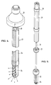
- the bundle is composed of six partial rods each having its own diffusion window 25.
- the light source 26 projects its light cone 27 excentrically on the desired partial rod and the light can be injected into each selected partial rod either by rotatively moving the light source along a circular path, or by tilting the lamp in an inclined position around a tilt point located in the axis of the bundle, or by applying an asymmetrical optical deviator.
- FIG 4 shows the general principle of such a composite light guide.
- the rods 29 have prismatic cross-section together forming a "daisy" design.
- Rings 30 keep the rods in position with respect to the main axis and to the outer cladding (not shown).
- the rings 30 are supported by a metal skeleton comprising a shaft 31, ribs 32 and radial spacers 33 fastened to the rings.
- a cap 34 secures the rods against axial displacement.
- the described lighting device is radiation-resistant up to 10 exp.8 rad, high temperature resistant up to 450°C, and it is vacuum proof.
- the invention is not restricted to the preferred embodiments described above.
- the lighting device may also, if necessary, be mounted in a horizontal or an inclined position. Instead of two windows and two bellows, only one window and one bellow may be provided.
Landscapes
- Physics & Mathematics (AREA)
- Engineering & Computer Science (AREA)
- General Engineering & Computer Science (AREA)
- High Energy & Nuclear Physics (AREA)
- General Physics & Mathematics (AREA)
- Optics & Photonics (AREA)
- Non-Portable Lighting Devices Or Systems Thereof (AREA)
- Investigating Or Analysing Materials By Optical Means (AREA)
Claims (5)
- Dispositif d'éclairage destiné à l'illumination d'une enceinte (7) close, comprenant une source de lumière (1) et au moins une barre en verre (2), qui est accouplée optiquement et mécaniquement à ladite source en s'étendant à travers une paroi (6) de l'enceinte et en étant pourvu d'un diffuseur de lumière (3) à son extrémité libre, est caractérisé en ce que la source de lumière (1) et au moins une barre en verre (2) constituent une unité mobile, qu'au moins une fenêtre (10, 11) étanche au gaz est interposée entre la source de lumière (1) et la barre en verre (2), qu'un tube d'accès passant à travers la paroi (6) et débouchant dans ladite enceinte (7) reçoit ladite unité mobile (1, 2) qui est logée de façon coulissante dans ce tube, qu'au moins un soufflet cylindrique (14, 15) est fixé de façon étanche audit tube d'accès (5) ainsi qu'au bord d'une des fenêtres (10, 11), et que le soufflet est dimensionné de façon à permettre au diffuseur (3) de pénétrer dans ladite enceinte (7) et d'en être retiré.
- Dispositif d'éclairage selon la revendication 1, caractérisé en ce qu'un faisceau de barres de verre (24, 29) parallèles entre elles formant un guide de lumière fendue est disposé dans l'unité mobile (26, 2), et que des moyens sont disposés entre la source de lumière (26) et ladite au moins une fenêtre pour focaliser le cône de lumière (27) sur une quelconque desdites barres.
- Dispositif d'éclairage selon la revendication 2, caractérisé en ce que les barres de verre (24, 29) sont maintenues dans une structure métallique composée d'une tige centrale (31) pourvue d'anneaux (30) attachés à celle-ci par des écarteurs radiaux (33), lesdits anneaux entourant lesdites barres.
- Dispositif d'éclairage suivant l'une quelconque des revendications précédentes, caractérisé en ce que deux fenêtres (10, 11) sont prévues, à travers lesquelles passe la lumière successivement.
- Dispositif d'éclairage selon la revendication 4, caractérisé en ce que chaque fenêtre (10, 11) est individuellement associée à un soufflet (14, 15), en assurant ainsi l'étanchéité, même dans le cas où des fuites se produisent à travers un soufflet ou une fenêtre.
Applications Claiming Priority (2)
| Application Number | Priority Date | Filing Date | Title |
|---|---|---|---|
| LU87151A LU87151A1 (de) | 1988-03-04 | 1988-03-04 | Beleuchtungsvorrichtung fuer geschlossene raeume |
| LU87151 | 1988-03-04 |
Publications (2)
| Publication Number | Publication Date |
|---|---|
| EP0331064A1 EP0331064A1 (fr) | 1989-09-06 |
| EP0331064B1 true EP0331064B1 (fr) | 1993-08-04 |
Family
ID=19731030
Family Applications (1)
| Application Number | Title | Priority Date | Filing Date |
|---|---|---|---|
| EP19890103373 Expired - Lifetime EP0331064B1 (fr) | 1988-03-04 | 1989-02-27 | Dispositif d'illumination pour illuminer des enceintes fermées |
Country Status (7)
| Country | Link |
|---|---|
| EP (1) | EP0331064B1 (fr) |
| DE (1) | DE68907950T2 (fr) |
| DK (1) | DK169007B1 (fr) |
| ES (1) | ES2042824T3 (fr) |
| IE (1) | IE62209B1 (fr) |
| LU (1) | LU87151A1 (fr) |
| PT (1) | PT89898B (fr) |
Families Citing this family (10)
| Publication number | Priority date | Publication date | Assignee | Title |
|---|---|---|---|---|
| EP0446692A1 (fr) * | 1990-03-15 | 1991-09-18 | Eta Ingenieurgesellschaft Für Energietechnik Und Energieanwendung Mbh | Dispositif d'éclairage avec guides de lumière, en particulier pour chambre froide et chambre antidéflagrante |
| EP0657685A1 (fr) * | 1993-11-12 | 1995-06-14 | General Electric Company | Source lumineuse à haute intensité à remplacement aisé pour système distributeur de lumière |
| GB9708450D0 (en) | 1997-04-26 | 1997-06-18 | British Nuclear Fuels Plc | Light assembly |
| SE9701798L (sv) * | 1997-05-15 | 1998-11-16 | Celsiustech Electronics Ab | Belysningsanordning samt förfarande för montering av belysningsanordningen |
| GB2356921A (en) * | 1999-12-02 | 2001-06-06 | John Clayton Ruddick | A lamp with a fibre optic cable to provide a light output externally of the lamp housing |
| GB0007215D0 (en) * | 2000-03-25 | 2000-05-17 | Tissuemed Ltd | Light source positioning device |
| RU2360163C1 (ru) * | 2007-12-04 | 2009-06-27 | Федеральное государственное образовательное учреждение высшего профессионального образования "Сибирский федеральный университет" (СФУ) | Устройство пространственного управления |
| FR2973152B1 (fr) * | 2011-03-23 | 2018-01-26 | Areva Nc | Installation etanche destinee a la manipulation de materiau en poudre |
| CN111308730B (zh) * | 2018-12-11 | 2024-07-16 | 核工业西南物理研究院 | 一种聚变装置玻璃窗口污染防护电控活动光栏 |
| EP3744428B1 (fr) * | 2019-05-31 | 2024-11-06 | Weiss Technik GmbH | Chambre d'essai |
Family Cites Families (3)
| Publication number | Priority date | Publication date | Assignee | Title |
|---|---|---|---|---|
| US1351562A (en) * | 1919-09-10 | 1920-08-31 | J B Wadman | Illusion apparatus |
| FR1475913A (fr) * | 1966-02-23 | 1967-04-07 | Commissariat Energie Atomique | Dispositif support de lampe d'éclairage à l'intérieur d'une enceinte étanche |
| US3813514A (en) * | 1972-10-16 | 1974-05-28 | J Canty | Light piping unit for supplying radiant energy to the interior of a pressure vessel |
-
1988
- 1988-03-04 LU LU87151A patent/LU87151A1/de unknown
-
1989
- 1989-02-09 DK DK59789A patent/DK169007B1/da not_active IP Right Cessation
- 1989-02-27 IE IE61989A patent/IE62209B1/en not_active IP Right Cessation
- 1989-02-27 ES ES89103373T patent/ES2042824T3/es not_active Expired - Lifetime
- 1989-02-27 EP EP19890103373 patent/EP0331064B1/fr not_active Expired - Lifetime
- 1989-02-27 DE DE1989607950 patent/DE68907950T2/de not_active Expired - Fee Related
- 1989-03-03 PT PT8989889A patent/PT89898B/pt not_active IP Right Cessation
Also Published As
| Publication number | Publication date |
|---|---|
| LU87151A1 (de) | 1989-10-26 |
| PT89898A (pt) | 1989-11-10 |
| DE68907950T2 (de) | 1993-11-18 |
| DK59789A (da) | 1989-09-05 |
| IE62209B1 (en) | 1995-01-11 |
| ES2042824T3 (es) | 1993-12-16 |
| EP0331064A1 (fr) | 1989-09-06 |
| DK59789D0 (da) | 1989-02-09 |
| IE890619L (en) | 1989-09-04 |
| DE68907950D1 (de) | 1993-09-09 |
| PT89898B (pt) | 1994-03-31 |
| DK169007B1 (da) | 1994-07-25 |
Similar Documents
| Publication | Publication Date | Title |
|---|---|---|
| EP0331064A1 (fr) | Dispositif d'illumination pour illuminer des enceintes fermées | |
| US4270845A (en) | Laser apparatus for operations | |
| KR0158676B1 (ko) | 용융 용기내 액상 금속에 원소분석 장치 및 레이저를 광학적으로 결합하기 위한 방법 및 장치 | |
| ES8100590A1 (es) | Dispositivo de inspeccion televisual de la superficie interior de un recinto cilindrico cerrado | |
| JP2799291B2 (ja) | 炉内検査装置 | |
| US3229577A (en) | Periscope having telescoping sections for viewing reactor interior | |
| JP2005515435A (ja) | 回折計及び回折分析方法 | |
| KR890013493A (ko) | 광학 비임 정렬 시스템 및 방법 | |
| US3737372A (en) | Installation for surveying the displacement of a structure in a nuclear reactor | |
| CA2075836A1 (fr) | Support de mecanisme de reglage de position pouvant etre utilise dans un systeme de reflecteurs | |
| KR840002381B1 (ko) | 방사선 조사 표적의 이동 및 위치 조정장치 | |
| US5544206A (en) | Reactor head work station | |
| JPH08510064A (ja) | 放射線遮蔽エンクロージャと共に使用される装置 | |
| WO1995024720A9 (fr) | Dispositif d'imagerie optique destine a etre utilise avec des enceintes blindees anti-radiations | |
| US3485548A (en) | Stereoscopic telescope for the remote viewing of objects placed in a sealed examination cave | |
| RU2839928C1 (ru) | Гамма-дефектоскоп затворного типа | |
| RU2067327C1 (ru) | Способ разделки топливной сборки ядерного реактора и устройство разделки для его осуществления | |
| EP1758130B1 (fr) | Dispositif de blindage de rayons X et dispositif de rayons X l'incorporant | |
| JP3335592B2 (ja) | 気密装置用の照明装置 | |
| US4912529A (en) | Apparatus and method to compensate for refraction of radiation | |
| KR102922897B1 (ko) | 광 수광이 가능한 사용후핵연료 캐니스터 및 이를 포함하는 내부 환경 모니터링 시스템 | |
| JPS647529Y2 (fr) | ||
| RU2227940C2 (ru) | Разгрузочно-загрузочная машина ядерного канального реактора | |
| RU2046254C1 (ru) | Светосигнальный огонь | |
| RU329U1 (ru) | Светосигнальный огонь |
Legal Events
| Date | Code | Title | Description |
|---|---|---|---|
| PUAI | Public reference made under article 153(3) epc to a published international application that has entered the european phase |
Free format text: ORIGINAL CODE: 0009012 |
|
| AK | Designated contracting states |
Kind code of ref document: A1 Designated state(s): BE DE ES FR GB GR IT LU NL |
|
| 17P | Request for examination filed |
Effective date: 19900305 |
|
| 17Q | First examination report despatched |
Effective date: 19921002 |
|
| GRAA | (expected) grant |
Free format text: ORIGINAL CODE: 0009210 |
|
| AK | Designated contracting states |
Kind code of ref document: B1 Designated state(s): BE DE ES FR GB GR IT LU NL |
|
| REF | Corresponds to: |
Ref document number: 68907950 Country of ref document: DE Date of ref document: 19930909 |
|
| ITF | It: translation for a ep patent filed | ||
| ET | Fr: translation filed | ||
| REG | Reference to a national code |
Ref country code: ES Ref legal event code: FG2A Ref document number: 2042824 Country of ref document: ES Kind code of ref document: T3 |
|
| REG | Reference to a national code |
Ref country code: GR Ref legal event code: FG4A Free format text: 3009289 |
|
| EPTA | Lu: last paid annual fee | ||
| PLBE | No opposition filed within time limit |
Free format text: ORIGINAL CODE: 0009261 |
|
| STAA | Information on the status of an ep patent application or granted ep patent |
Free format text: STATUS: NO OPPOSITION FILED WITHIN TIME LIMIT |
|
| 26N | No opposition filed | ||
| PGFP | Annual fee paid to national office [announced via postgrant information from national office to epo] |
Ref country code: LU Payment date: 19961201 Year of fee payment: 9 |
|
| PGFP | Annual fee paid to national office [announced via postgrant information from national office to epo] |
Ref country code: BE Payment date: 19961213 Year of fee payment: 9 |
|
| PGFP | Annual fee paid to national office [announced via postgrant information from national office to epo] |
Ref country code: GR Payment date: 19961220 Year of fee payment: 9 |
|
| PGFP | Annual fee paid to national office [announced via postgrant information from national office to epo] |
Ref country code: GB Payment date: 19970127 Year of fee payment: 9 |
|
| PGFP | Annual fee paid to national office [announced via postgrant information from national office to epo] |
Ref country code: FR Payment date: 19970204 Year of fee payment: 9 |
|
| PGFP | Annual fee paid to national office [announced via postgrant information from national office to epo] |
Ref country code: ES Payment date: 19970214 Year of fee payment: 9 |
|
| PGFP | Annual fee paid to national office [announced via postgrant information from national office to epo] |
Ref country code: NL Payment date: 19970228 Year of fee payment: 9 |
|
| PGFP | Annual fee paid to national office [announced via postgrant information from national office to epo] |
Ref country code: DE Payment date: 19970324 Year of fee payment: 9 |
|
| PG25 | Lapsed in a contracting state [announced via postgrant information from national office to epo] |
Ref country code: LU Free format text: LAPSE BECAUSE OF NON-PAYMENT OF DUE FEES Effective date: 19980227 Ref country code: GB Free format text: LAPSE BECAUSE OF NON-PAYMENT OF DUE FEES Effective date: 19980227 |
|
| PG25 | Lapsed in a contracting state [announced via postgrant information from national office to epo] |
Ref country code: GR Free format text: LAPSE BECAUSE OF NON-PAYMENT OF DUE FEES Effective date: 19980228 Ref country code: FR Free format text: THE PATENT HAS BEEN ANNULLED BY A DECISION OF A NATIONAL AUTHORITY Effective date: 19980228 Ref country code: ES Free format text: LAPSE BECAUSE OF NON-PAYMENT OF DUE FEES Effective date: 19980228 Ref country code: BE Free format text: LAPSE BECAUSE OF NON-PAYMENT OF DUE FEES Effective date: 19980228 |
|
| BERE | Be: lapsed |
Owner name: EUROPEAN ATOMIC ENERGY COMMUNITY EURATOM Effective date: 19980228 |
|
| PG25 | Lapsed in a contracting state [announced via postgrant information from national office to epo] |
Ref country code: NL Free format text: LAPSE BECAUSE OF NON-PAYMENT OF DUE FEES Effective date: 19980901 |
|
| GBPC | Gb: european patent ceased through non-payment of renewal fee |
Effective date: 19980227 |
|
| NLV4 | Nl: lapsed or anulled due to non-payment of the annual fee |
Effective date: 19980901 |
|
| PG25 | Lapsed in a contracting state [announced via postgrant information from national office to epo] |
Ref country code: DE Free format text: LAPSE BECAUSE OF NON-PAYMENT OF DUE FEES Effective date: 19981103 |
|
| REG | Reference to a national code |
Ref country code: FR Ref legal event code: ST |
|
| REG | Reference to a national code |
Ref country code: ES Ref legal event code: FD2A Effective date: 20000403 |
|
| PG25 | Lapsed in a contracting state [announced via postgrant information from national office to epo] |
Ref country code: IT Free format text: LAPSE BECAUSE OF NON-PAYMENT OF DUE FEES;WARNING: LAPSES OF ITALIAN PATENTS WITH EFFECTIVE DATE BEFORE 2007 MAY HAVE OCCURRED AT ANY TIME BEFORE 2007. THE CORRECT EFFECTIVE DATE MAY BE DIFFERENT FROM THE ONE RECORDED. Effective date: 20050227 |