EP0331024A2 - Verfahren zur Herstellung eines Arbeitsschutzhandschuhs - Google Patents
Verfahren zur Herstellung eines Arbeitsschutzhandschuhs Download PDFInfo
- Publication number
- EP0331024A2 EP0331024A2 EP89103232A EP89103232A EP0331024A2 EP 0331024 A2 EP0331024 A2 EP 0331024A2 EP 89103232 A EP89103232 A EP 89103232A EP 89103232 A EP89103232 A EP 89103232A EP 0331024 A2 EP0331024 A2 EP 0331024A2
- Authority
- EP
- European Patent Office
- Prior art keywords
- mold
- glove
- sprue
- injection mold
- protective
- Prior art date
- Legal status (The legal status is an assumption and is not a legal conclusion. Google has not performed a legal analysis and makes no representation as to the accuracy of the status listed.)
- Withdrawn
Links
Images
Classifications
-
- B—PERFORMING OPERATIONS; TRANSPORTING
- B29—WORKING OF PLASTICS; WORKING OF SUBSTANCES IN A PLASTIC STATE IN GENERAL
- B29C—SHAPING OR JOINING OF PLASTICS; SHAPING OF MATERIAL IN A PLASTIC STATE, NOT OTHERWISE PROVIDED FOR; AFTER-TREATMENT OF THE SHAPED PRODUCTS, e.g. REPAIRING
- B29C45/00—Injection moulding, i.e. forcing the required volume of moulding material through a nozzle into a closed mould; Apparatus therefor
- B29C45/17—Component parts, details or accessories; Auxiliary operations
- B29C45/26—Moulds
- B29C45/27—Sprue channels ; Runner channels or runner nozzles
- B29C45/2701—Details not specific to hot or cold runner channels
-
- B—PERFORMING OPERATIONS; TRANSPORTING
- B29—WORKING OF PLASTICS; WORKING OF SUBSTANCES IN A PLASTIC STATE IN GENERAL
- B29C—SHAPING OR JOINING OF PLASTICS; SHAPING OF MATERIAL IN A PLASTIC STATE, NOT OTHERWISE PROVIDED FOR; AFTER-TREATMENT OF THE SHAPED PRODUCTS, e.g. REPAIRING
- B29C45/00—Injection moulding, i.e. forcing the required volume of moulding material through a nozzle into a closed mould; Apparatus therefor
- B29C45/17—Component parts, details or accessories; Auxiliary operations
- B29C45/26—Moulds
- B29C45/34—Moulds having venting means
-
- B—PERFORMING OPERATIONS; TRANSPORTING
- B29—WORKING OF PLASTICS; WORKING OF SUBSTANCES IN A PLASTIC STATE IN GENERAL
- B29C—SHAPING OR JOINING OF PLASTICS; SHAPING OF MATERIAL IN A PLASTIC STATE, NOT OTHERWISE PROVIDED FOR; AFTER-TREATMENT OF THE SHAPED PRODUCTS, e.g. REPAIRING
- B29C45/00—Injection moulding, i.e. forcing the required volume of moulding material through a nozzle into a closed mould; Apparatus therefor
- B29C45/17—Component parts, details or accessories; Auxiliary operations
- B29C45/26—Moulds
- B29C45/36—Moulds having means for locating or centering cores
-
- B—PERFORMING OPERATIONS; TRANSPORTING
- B29—WORKING OF PLASTICS; WORKING OF SUBSTANCES IN A PLASTIC STATE IN GENERAL
- B29D—PRODUCING PARTICULAR ARTICLES FROM PLASTICS OR FROM SUBSTANCES IN A PLASTIC STATE
- B29D99/00—Subject matter not provided for in other groups of this subclass
- B29D99/0064—Producing wearing apparel
- B29D99/0067—Gloves
-
- B—PERFORMING OPERATIONS; TRANSPORTING
- B29—WORKING OF PLASTICS; WORKING OF SUBSTANCES IN A PLASTIC STATE IN GENERAL
- B29L—INDEXING SCHEME ASSOCIATED WITH SUBCLASS B29C, RELATING TO PARTICULAR ARTICLES
- B29L2031/00—Other particular articles
- B29L2031/48—Wearing apparel
- B29L2031/4842—Outerwear
- B29L2031/4864—Gloves
-
- Y—GENERAL TAGGING OF NEW TECHNOLOGICAL DEVELOPMENTS; GENERAL TAGGING OF CROSS-SECTIONAL TECHNOLOGIES SPANNING OVER SEVERAL SECTIONS OF THE IPC; TECHNICAL SUBJECTS COVERED BY FORMER USPC CROSS-REFERENCE ART COLLECTIONS [XRACs] AND DIGESTS
- Y10—TECHNICAL SUBJECTS COVERED BY FORMER USPC
- Y10S—TECHNICAL SUBJECTS COVERED BY FORMER USPC CROSS-REFERENCE ART COLLECTIONS [XRACs] AND DIGESTS
- Y10S264/00—Plastic and nonmetallic article shaping or treating: processes
- Y10S264/30—Use of anatomy in making a mold or using said mold
-
- Y—GENERAL TAGGING OF NEW TECHNOLOGICAL DEVELOPMENTS; GENERAL TAGGING OF CROSS-SECTIONAL TECHNOLOGIES SPANNING OVER SEVERAL SECTIONS OF THE IPC; TECHNICAL SUBJECTS COVERED BY FORMER USPC CROSS-REFERENCE ART COLLECTIONS [XRACs] AND DIGESTS
- Y10—TECHNICAL SUBJECTS COVERED BY FORMER USPC
- Y10S—TECHNICAL SUBJECTS COVERED BY FORMER USPC CROSS-REFERENCE ART COLLECTIONS [XRACs] AND DIGESTS
- Y10S425/00—Plastic article or earthenware shaping or treating: apparatus
- Y10S425/051—Sprue removal
-
- Y—GENERAL TAGGING OF NEW TECHNOLOGICAL DEVELOPMENTS; GENERAL TAGGING OF CROSS-SECTIONAL TECHNOLOGIES SPANNING OVER SEVERAL SECTIONS OF THE IPC; TECHNICAL SUBJECTS COVERED BY FORMER USPC CROSS-REFERENCE ART COLLECTIONS [XRACs] AND DIGESTS
- Y10—TECHNICAL SUBJECTS COVERED BY FORMER USPC
- Y10S—TECHNICAL SUBJECTS COVERED BY FORMER USPC CROSS-REFERENCE ART COLLECTIONS [XRACs] AND DIGESTS
- Y10S425/00—Plastic article or earthenware shaping or treating: apparatus
- Y10S425/806—Flash removal
-
- Y—GENERAL TAGGING OF NEW TECHNOLOGICAL DEVELOPMENTS; GENERAL TAGGING OF CROSS-SECTIONAL TECHNOLOGIES SPANNING OVER SEVERAL SECTIONS OF THE IPC; TECHNICAL SUBJECTS COVERED BY FORMER USPC CROSS-REFERENCE ART COLLECTIONS [XRACs] AND DIGESTS
- Y10—TECHNICAL SUBJECTS COVERED BY FORMER USPC
- Y10S—TECHNICAL SUBJECTS COVERED BY FORMER USPC CROSS-REFERENCE ART COLLECTIONS [XRACs] AND DIGESTS
- Y10S425/00—Plastic article or earthenware shaping or treating: apparatus
- Y10S425/812—Venting
Definitions
- the invention relates to a method for producing an occupational safety glove, in particular for the electrical sector, in which plastic material is injected into a mold having a core hand under high pressure.
- Safety gloves are usually made of rubber using the immersion process.
- uniform wall thicknesses can be achieved without difficulty. If larger wall thicknesses are required for the electrical sector in order to achieve an electrical insulation effect, the dipping process can be repeated several times, so that the wall thickness increases with each operation.
- a protective glove is intended for the electrical sector, for example, and is intended to protect the user from voltages of up to 40 kV, for example, then its wall thickness must not fall below a minimum at any point because it could lead to electrical breakdowns. Apart from the problem of falling below the minimum wall thicknesses, air pockets are relatively easy in the injection molding process, which also reduces the insulation effect. The area of the parting line would also be critical in the case of such protective gloves produced by injection molding. For this reason, there are only safety gloves made for diving in the electrical sector.
- the invention has for its object to develop an injection molding process of the type mentioned for the production of protective gloves with which very uniform, larger wall thicknesses can be achieved, so that the protective glove can be used as a safety glove for the electrical sector.
- the protective working glove is produced with a sprue flange adjoining its glove cuff within an injection mold having a core hand that is flying on the side of the glove cuff, in that the material is fed to the sprue flange at least two opposite points via sprue channels and up to to the fingertips evenly distributed in the injection mold and that after the crosslinking of the material and the demolding of the protective glove the sprue flange with its sprues is cut off from the protective glove.
- a sprue flange is provided on the work safety glove and injected on two opposite sides, the plastic material is distributed in the mold very evenly without shifting the core hand to one side, which would lead to different wall thicknesses. Since the sprue channels are only provided on the sprue flange and nowhere in the area of the later occupational safety glove, the uniform structure of the occupational safety glove is not interrupted by such sprue channels.
- a particular advantage of the injection molding process over the immersion process is that the material does not have to be dissolved in solvents.
- the injection molding process is more environmentally friendly because it uses solid rubber.
- the method according to the invention can be carried out with particularly little effort if an injection mold consisting of two mold halves is used and if these mold halves are each moved from one side over the core hand to close the injection mold.
- Air inclusions can be avoided in a simple manner by providing suction channels leading to the fingertips in the injection mold, via which the air displaced there is sucked off at the fingertips during the spraying.
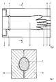
- FIG. 1 shows an injection mold, a mold half 1, in which a core hand 2 is inserted.
- This core hand 2 is seen in the drawing only on the left side, that is, in connection with the glove cuff, overhung.
- the mold half 1 surrounds the core hand 2 with a small distance.
- a sprue flange 3 is formed in it at the arm-side end of the glove, to which a sprue channel 4, 5 leads from above and below.
- the plastic material is injected into the injection mold via these sprue channels 4, 5.
- suction channels 6-10 open into the cavity between the injection mold and the core hand 2 in the region of the fingertips.
- the sprue flange 3 is cut off behind a circumferential bead 11 serving as a rolled edge, so that no sprue remains on the occupational safety glove.
- a circumferential bead 11 serving as a rolled edge
- the sectional view in FIG. 2 illustrates that the injection mold consists of two mold halves 1a, 1b, which grip from the side over the core hand and are moved apart to the side for demolding.
Landscapes
- Engineering & Computer Science (AREA)
- Mechanical Engineering (AREA)
- Manufacturing & Machinery (AREA)
- Gloves (AREA)
- Moulds For Moulding Plastics Or The Like (AREA)
- Injection Moulding Of Plastics Or The Like (AREA)
- Professional, Industrial, Or Sporting Protective Garments (AREA)
Abstract
Ein Arbeitsschutzhandschuh für den Elektrobereich wird im Spritzgußverfahren hergestellt. Hierbei wird in einer Spritzgußform plastisches Material von zwei gegenüberliegenden Seiten her über einen Angußflansch eingespritzt. Dieser Angußflansch wird nach dem Ausformen des Arbeitsschutzhandschuhes von ihm abgeschnitten.
Description
- Die Erfindung bezieht sich auf ein Verfahren zur Herstellung eines Arbeitsschutzhandschuhs, insbesondere für den Elektrobereich, bei dem unter hohem Druck plastisches Material in eine eine Kernhand aufweisende Form gespritzt wird.
- Üblicherweise werden Arbeitsschutzhandschuhe aus Kautschuk im Tauchverfahren hergestellt. Im Tauchverfahren lassen sich ohne Schwierigkeiten gleichmäßige Wandstärken erzielen. Sind für den Elektrobereich größere Wandstärken erforderlich, um eine elektrische Isolationswirkung zu erzielen, so kann man den Tauchvorgang mehrmals wiederholen, so daß sich die Wandstärke mit jedem Arbeitsgang erhöht.
- Wenn man einen Arbeitsschutzhandschuh im Spritzgußverfahren herstellen will, dann bereitet das Erzielen einer gleichmäßigen Wandstärke Schwierigkeiten. Ist ein Arbeitsschutzhandschuh beispielsweise für den Elektrobereich bestimmt und soll den Benutzer vor Spannungen bis beispielsweise 40 kV schützen, dann darf seine Wandstärke an keiner Stelle ein Mindestmaß unterschreiten, weil es dort zu elektrischen Spannungsdurchschlägen kommen könnte. Abgesehen vom Problem des Unterschreitens von Mindestwandstärken kommt es beim Spritzgußverfahren relativ leicht zu Lufteinschlüssen, wodurch ebenfalls die Isolationswirkung vermindert wird. Auch der Bereich der Trennfuge wäre bei solchen im Spritzgußverfahren hergestellten Arbeitsschutzhandschuhen kritisch. Deshalb gibt es für den Elektrobereich bislang nur durch Tauchen erzeugte Sicherheitshandschuhe.
- Der Erfindung liegt die Aufgabe zugrunde, ein Spritzgußverfahren der eingangs genannten Art zu Herstellung von Arbeitsschutzhandschuhen zu entwickeln, mit dem sich sehr gleichmäßige, größere Wandstärken erzielen lassen, so daß der Arbeitsschutzhandschuh als Sicherheitshandschuh für den Elektrobereich verwendbar ist.
- Diese Aufgabe wird erfindungsgemäß dadurch gelöst, daß innerhalb einer eine fliegend an der Seite der Handschuhmanschette gelagerte Kernhand aufweisenden Spritzgußform der Arbeitsschutzhandschuh mit einem sich seiner Handschuhmanschette anschließenden Angußflansch erzeugt wird, indem das Material an zumindest zwei gegenüberliegenden Stellen über Angußkanäle dem Angußflansch zugeführt wird und sich bis zu den Fingerkuppen gleichmäßig in der Spritzgußform verteilt und daß nach dem Vernetzen des Materials und dem Entformen des Arbeitsschutzhandschuhes der Angußflansch mit seinen Angüssen vom Arbeitsschutzhandschuh abgeschnitten wird.
- Dadurch, daß gemäß der Erfindung am Arbeitsschutzhandschuh ein Angußflansch vorgesehen und an zwei gegenüberliegenden Seiten eingespritzt wird, verteilt sich das plastische Material in der Form sehr gleichmäßig, ohne die Kernhand nach einer Seite hin zu verschieben, was zu unterschiedlichen Wandstärken führen würde. Da die Angußkanäle nur am Angußflansch und nirgends im Bereich des späteren Arbeitsschutzhandschuhs vorgesehen sind, wird die gleichmäßige Struktur des Arbeitsschutzhandschuhs nicht durch solche Angußkanäle unterbrochen.
- Ein besonderer Vorteil des Spritzgußverfahrens gegenüber dem Tauchverfahren liegt darin, daß das Material nicht in Lösungsmitteln gelöst werden muß. Das Spritzgußverfahren ist umweltfreundlicher, weil bei ihm Festkautschuk verarbeitet wird.
- Das erfindungsgemäße Verfahren kann mit besonders geringem Aufwand durchgeführt werden, wenn eine aus zwei Formhälften bestehende Spritzgußform verwendet wird und wenn diese Formhälften zum Schließen der Spritzgußform jeweils von einer Seite über die Kernhand gefahren werden.
- Lufteinschlüsse lassen sich auf einfache Weise dadurch vermeiden, daß in der Spritzgußform zu den Fingerkuppen führende Absaugkanäle vorgesehen werden, über die während des Spritzens an den Fingerkuppen die dorthin verdrängte Luft abgesaugt wird.
- Bei im Spritzgußverfahren hergestellten Teilen erkennt man notwendigerweise den Trennfugenbereich der Spritzgußform. Das kann bei einem Arbeitsschutzhandschuh sehr einfach dadurch vermieden werden, daß der Arbeitschutzhandschuh nach dem Entformen gewendet wird.
- Zur weiteren Erläuterung des erfindungsgemäßen Verfahrens ist in der Zeichnung eine Spritzgußform dargestellt und wird nachfolgend erläutert.
- Die Figur 1 zeigt von einer Spritzgußform eine Formhälfte 1, in der eine Kernhand 2 eingesetzt ist. Diese Kernhand 2 ist in der Zeichnung gesehen ausschließlich an der linken Seite, also im Anschluß an die Handschuhmanschette, fliegend gelagert. Die Formhälfte 1 umgibt die Kernhand 2 mit geringem Abstand. In ihr ist am armseitigen Ende des Handschuhs ein Angußflansch 3 geformt, zu dem von oben und unten jeweils ein Angußkanal 4, 5 führt. Über diese Angußkanäle 4, 5 wird das plastische Material in die Spritzgußform eingespritzt. Um die dabei verdrängte Luft abführen zu können, münden im Bereich der Fingerkuppen Absaugkanäle 6 - 10 in den Hohlraum zwischen der Spritzgußform und der Kernhand 2.
- Nach dem Spritzen eines Arbeitsschutzhandschuhs wird der Angußflansch 3 hinter einem als Rollrand dienenden, umlaufenden Wulst 11 abgeschnitten, so daß am Arbeitsschutzhandschuh keine Angüsse verbleiben. Durch Wenden des Arbeitsschutzhandschuhes kann man erreichen, daß dieser außenseitig völlig glatt ist und keine Trennfuge zu sehen ist.
- Die Schnittdarstellung in Figur 2 verdeutlicht, daß die Spritzgußform aus zwei Formhälften 1a, 1b besteht, welche von der Seite her über die Kernhand greifen und zum Entformen zur Seite hin auseinandergefahren werden.
Claims (4)
1. Verfahren zur Herstellung eines Arbeitsschutzhandschuhs, insbesondere für den Elektrobereich, bei dem unter hohem Druck plastisches Material in eine eine Kernhand aufweisende Form gespritzt wird, dadurch gekennzeichnet, daß innerhalb einer eine fliegend an der Seite der Handschuhmanschette gelagerte Kernhand aufweisenden Spritzgußform der Arbeitsschutzhandschuh mit einem sich seiner Handschuhmanschette anschließenden Angußflansch erzeugt wird, indem das Material an zumindest zwei gegenüberliegenden Stellen über Angußkanäle dem Angußflansch zugeführt wird und sich bis zu den Fingerkuppen gleichmäßig in der Spritzgußform verteilt und daß nach dem Vernetzen des Materials und dem Entformen des Arbeitsschutzhandschuhes der Angußflansch mit seinen Angüssen vom Arbeitschutzhandschuh abgeschnitten wird.
2. Verfahren nach Anspruch 1, dadurch gekennzeichnet, daß eine aus zwei Formhälften bestehende Spritzgußform verwendet wird und daß diese Formhälften zum Schließen der Spritzgußform jeweils von einer Seite über die Kernhand gefahren werden.
3. Verfahren nach den Ansprüchen 1 oder 2, dadurch gekennzeichnet, daß in der Spritzgußform zu den Fingerkuppen führende Absaugkanäle vorgesehen werden, über die während des Spritzens an den Fingerkuppen die dorthin verdrängte Luft abgesaugt wird.
4. Verfahren nach zumindest einem der vorangehenden Ansprüche, dadurch gekennzeichnet, daß der Arbeitsschutzhandschuh nach dem Entformen gewendet wird.
Applications Claiming Priority (2)
| Application Number | Priority Date | Filing Date | Title |
|---|---|---|---|
| DE3807092 | 1988-03-04 | ||
| DE3807092A DE3807092A1 (de) | 1988-03-04 | 1988-03-04 | Verfahren zur herstellung eines arbeitsschutzhandschuhs |
Publications (2)
| Publication Number | Publication Date |
|---|---|
| EP0331024A2 true EP0331024A2 (de) | 1989-09-06 |
| EP0331024A3 EP0331024A3 (de) | 1991-08-07 |
Family
ID=6348863
Family Applications (1)
| Application Number | Title | Priority Date | Filing Date |
|---|---|---|---|
| EP19890103232 Withdrawn EP0331024A3 (de) | 1988-03-04 | 1989-02-24 | Verfahren zur Herstellung eines Arbeitsschutzhandschuhs |
Country Status (4)
| Country | Link |
|---|---|
| US (1) | US4921672A (de) |
| EP (1) | EP0331024A3 (de) |
| JP (1) | JPH0270414A (de) |
| DE (1) | DE3807092A1 (de) |
Cited By (1)
| Publication number | Priority date | Publication date | Assignee | Title |
|---|---|---|---|---|
| EP2967172A4 (de) * | 2013-03-14 | 2016-11-23 | James B Rauckman | Verfahren zur herstellung von individuell konfigurierten leitungsverleger-handschuhen |
Families Citing this family (35)
| Publication number | Priority date | Publication date | Assignee | Title |
|---|---|---|---|---|
| GB9222865D0 (en) * | 1992-10-31 | 1992-12-16 | Smith & Nephew | Medical apparatus |
| US5451439A (en) * | 1994-01-14 | 1995-09-19 | Electric Power Research Institute, Inc. | Thermoplastic elastomer substitute for natural rubber |
| US8393932B1 (en) | 1997-07-24 | 2013-03-12 | Genie Toys Plc | Doll'S clothing and play set |
| US6941580B2 (en) * | 2000-09-22 | 2005-09-13 | Nestor Kolcio | Method for accessing electrical components with gloved hands |
| WO2005102087A2 (en) * | 2004-04-16 | 2005-11-03 | Magla Worldwide, Ltd. | Gloves with reinforcing elements and methods for making same |
| CN100355390C (zh) * | 2005-03-15 | 2007-12-19 | 深圳迈瑞生物医疗电子股份有限公司 | 硅胶指套血氧探头封线的方法和模具 |
| US20070118963A1 (en) * | 2005-11-30 | 2007-05-31 | Snyder Bruce A | Body mitt and apparatus for molding the same |
| US20090126074A1 (en) * | 2006-11-03 | 2009-05-21 | Henry Mattesky | Gloves with reinforcing elements and methods for making same |
| US8512615B1 (en) | 2007-04-04 | 2013-08-20 | Medine Industries, Inc. | Methods for making customized gloves and formers |
| US9555567B2 (en) | 2007-07-16 | 2017-01-31 | Madgrip Holdings, Llc | Utility glove |
| US9498009B2 (en) | 2007-07-16 | 2016-11-22 | Madgrip Holdings, Llc | Utility glove |
| US20090038052A1 (en) * | 2007-07-16 | 2009-02-12 | David Gellis | Utility glove |
| US8225730B2 (en) * | 2009-08-21 | 2012-07-24 | Chuan-Hsin Lo | Method of making a ball glove |
| JP5443919B2 (ja) | 2009-09-18 | 2014-03-19 | ユニ・チャーム株式会社 | 吸収性物品の製造方法、及び製造装置 |
| US20110198777A1 (en) * | 2010-02-17 | 2011-08-18 | Der-Lin Liou | Method for manufacturing seamless thin-walled articles with thermoplastic materials |
| US20110197896A1 (en) * | 2010-02-17 | 2011-08-18 | Der-Lin Liou | Elastic seamed thin-walled article with a single opening |
| CN102145522B (zh) * | 2011-02-25 | 2013-04-24 | 陆培功 | 用于模压的橡胶手形手套用钢模具及其镶块 |
| US9707715B2 (en) | 2011-10-31 | 2017-07-18 | Kimberly-Clark Worldwide, Inc. | Elastomeric articles having a welded seam made from a multi-layer film |
| US8566965B2 (en) | 2011-10-31 | 2013-10-29 | Kimberly-Clark Worldwide, Inc. | Elastomeric articles having a welded seam that possess strength and elasticity |
| CN102672884B (zh) * | 2012-06-11 | 2014-05-07 | 高密市利昌劳保用品工贸有限公司 | 一种纤维手套橡胶涂层注胶式制备装置 |
| US9174138B2 (en) | 2013-03-05 | 2015-11-03 | Genie Toys Plc | Playsets with molded shells |
| US9370209B2 (en) * | 2014-09-19 | 2016-06-21 | Summit Glove Inc. | Method of fabricating a glove with a widened cuff area |
| US12446639B2 (en) | 2015-04-24 | 2025-10-21 | Summit Glove Inc. | Drug resistant glove |
| USD783229S1 (en) | 2015-09-30 | 2017-04-11 | Madgrip Holdings, Llc | Glove |
| USD789652S1 (en) | 2015-09-30 | 2017-06-20 | Madgrip Holdings, Llc | Glove |
| CH711895B1 (de) * | 2015-12-10 | 2020-05-29 | G Zag Ag C/O Jmp Treuhand & Inkasso Ag | Verfahren zur Herstellung von Elektro-Isolationsprodukten aus synthetischem Polyisopren (IR) sowie derartige Elektro-Isolationsprodukte. |
| USD893129S1 (en) | 2016-05-25 | 2020-08-18 | Summit Glove Inc. | Patterned glove with a flared cuff |
| USD895228S1 (en) | 2016-05-25 | 2020-09-08 | Summit Glove Inc. | Patterned glove with a straight cuff |
| US20190281915A1 (en) * | 2016-07-20 | 2019-09-19 | F.F.P. Technologies Ltd. | Seamless wearable structure garment |
| US10413004B1 (en) | 2018-05-01 | 2019-09-17 | Ross Rudolph | Protective gloves with improved fingertip fitment and methods and mold-forms for manufacturing such gloves |
| GB2590646B (en) * | 2019-12-20 | 2024-10-23 | Design Blue Ltd | Impact resistant garment |
| CN111844642B (zh) * | 2020-07-23 | 2022-03-08 | 徐州华通手套有限公司 | 一种医用手套加工设备及其使用方法 |
| KR102803595B1 (ko) * | 2022-06-14 | 2025-05-08 | 한국생산기술연구원 | 로봇 핸드용 글로브, 이를 포함하는 로봇핸드, 로봇 핸드용 글로브 제조장치 및 그 제조방법 |
| CN119585095A (zh) * | 2022-07-20 | 2025-03-07 | 巴斯夫欧洲公司 | 用于生产中空模制零件的方法及由其获得的中空模制零件 |
| WO2026065524A1 (zh) * | 2024-09-30 | 2026-04-02 | 上海众安全运动用品有限公司 | 手套结构及其制造方法 |
Family Cites Families (17)
| Publication number | Priority date | Publication date | Assignee | Title |
|---|---|---|---|---|
| US1951377A (en) * | 1930-09-22 | 1934-03-20 | Duniop Rubber Company Ltd | Method of forming rubber gloves |
| US2895206A (en) * | 1955-12-29 | 1959-07-21 | Jr Rayburn W Hemphill | Apparatus for producing roughened surface glove forms or the like |
| FR1359189A (fr) * | 1963-02-19 | 1964-04-24 | Gant de protection et son procédé de fabrication | |
| DE1296335B (de) * | 1964-05-22 | 1969-05-29 | Desma Werke Gmbh | Verfahren und Vorrichtung zum Spritzgiessen von Hohlkoerpern |
| US3331904A (en) * | 1966-10-10 | 1967-07-18 | Friedman Jules | Method for making plastic buttons |
| FR1503301A (fr) * | 1966-12-06 | 1967-11-24 | Becton Dickinson Co | Procédé et appareil pour démouler des objets en matière plastique |
| US3568973A (en) * | 1969-05-02 | 1971-03-09 | Flambeau Plastics Corp | Edge gating of thin wall containers |
| FR2050590A5 (de) * | 1969-06-18 | 1971-04-02 | Sidel Sa | |
| US3626051A (en) * | 1969-09-19 | 1971-12-07 | James P Liautaud | Injection molding encapsulation of paper-wound flyback transformers and the like |
| US3846531A (en) * | 1971-03-03 | 1974-11-05 | Monsanto Co | Finishing hollow blow molded articles |
| US3855380A (en) * | 1971-06-09 | 1974-12-17 | Wheeling Stamping Co | Method for manufacturing unitary, seamless, collapsible thermoplastic tubes |
| DE2160667A1 (de) * | 1971-12-07 | 1973-06-14 | Raimund W Vogel | Vorrichtung zum herstellen von werkstuecken aus giess- oder spritzfaehigen kunststoffen |
| US3865666A (en) * | 1973-05-08 | 1975-02-11 | Int Paper Co | Method of making a catheter |
| FR2286702A1 (fr) * | 1974-10-02 | 1976-04-30 | Guen & Hemidy Le | Procede et machine pour le moulage par injection de pieces constituees de plusieurs matiere differentes |
| US4126291A (en) * | 1974-10-18 | 1978-11-21 | California Injection Molding Co., Inc. | Injection mold for elongated, hollow articles |
| DE7631476U1 (de) * | 1976-10-08 | 1977-01-27 | Fa. Carl Freudenberg, 6940 Weinheim | Rbeitshandschuh |
| US4750877A (en) * | 1983-05-23 | 1988-06-14 | Taut, Inc. | Injection molding of a thin-walled elongated tubular product such as a catheter |
-
1988
- 1988-03-04 DE DE3807092A patent/DE3807092A1/de not_active Withdrawn
-
1989
- 1989-02-24 EP EP19890103232 patent/EP0331024A3/de not_active Withdrawn
- 1989-02-24 US US07/315,100 patent/US4921672A/en not_active Expired - Fee Related
- 1989-03-02 JP JP1048705A patent/JPH0270414A/ja active Pending
Cited By (1)
| Publication number | Priority date | Publication date | Assignee | Title |
|---|---|---|---|---|
| EP2967172A4 (de) * | 2013-03-14 | 2016-11-23 | James B Rauckman | Verfahren zur herstellung von individuell konfigurierten leitungsverleger-handschuhen |
Also Published As
| Publication number | Publication date |
|---|---|
| JPH0270414A (ja) | 1990-03-09 |
| US4921672A (en) | 1990-05-01 |
| EP0331024A3 (de) | 1991-08-07 |
| DE3807092A1 (de) | 1989-09-14 |
Similar Documents
| Publication | Publication Date | Title |
|---|---|---|
| EP0331024A2 (de) | Verfahren zur Herstellung eines Arbeitsschutzhandschuhs | |
| DE3939869C2 (de) | Spritzgießform | |
| EP0210587B1 (de) | Verfahren zur Herstellung eines Polsterelements und Vorrichtung zur Durchführung dieses Verfahrens | |
| DE3735099A1 (de) | Verfahren und vorrichtung zur herstellung von mehrschicht-formteilen | |
| DE1279326B (de) | Spritzgiessverfahren zum Herstellen eines Ringes aus gesintertem, ferromagnetischem Oxydmaterial und einem in dem Ring befindlichen Kern aus thermoplastischen oder duroplastischen Kunststoffen sowie eine Spritzgiessform zur Durchfuehrung des Verfahrens | |
| EP0458250A2 (de) | Verfahren und Vorrichtung zur Entformung eines Garantiebands einer Verschlusskappe | |
| EP0147571A2 (de) | Werkzeug zum Spritzgiessen von Gegenständen aus Kunststoff | |
| EP0671251A1 (de) | Spritzgussverfahren und Vorrichtung zur Durchführung des Verfahrens | |
| DE3003903C2 (de) | Spritzgießform zum Herstellen von geformten Gegenständen durch Hinterspritzen von Überzugsmaterialien | |
| EP3285983B1 (de) | Verfahren zum herstellen eines mehrteiligen kunststoffbauteils sowie mehrteiliges kunststoffbauteil | |
| DE3444532C2 (de) | Mehrteilige Spritzgießform | |
| EP0419953A2 (de) | Vorrichtung zum zweischichtigen Spritzgiessen | |
| DE69201063T2 (de) | Herstellungsverfahren eines Frequenzadapters. | |
| DE4217343C2 (de) | Spritzgießform zum Herstellen eines Formteils aus Kunststoff | |
| DE19615309B4 (de) | Verfahren, spritzgegossener Körper und Spritzgießform zur Herstellung eines spritzgegossenen Körpers | |
| DE69423136T2 (de) | Umgossene Verglasung und Vorrichtung zu deren Herstellung | |
| DE2712824A1 (de) | Stator eines aussenlaeufermotors | |
| DE3735735C2 (de) | ||
| DE19536759C2 (de) | Verfahren zur Herstellung eines Rohrs | |
| DE3334332A1 (de) | Verfahren und hohlkoerper zur herstellung einer gleitfuehrung zwischen zwei relativ zueinander beweglichen bauteilen | |
| DE2436657B2 (de) | Vorrichtung zur herstellung von unterdruck-giessformen | |
| DE4204627C2 (de) | Lagerachse für Sonnenblenden von Fahrzeugen und Verfahren zum Herstellen einer solchen | |
| EP1338398A1 (de) | Vorrichtung zum Herstellen von mehrkomponentigen Kunststoffformteilen | |
| DE4317233A1 (de) | Verfahren zur Herstellung eines Kantenschutzes als Umrandung an dekorbeschichteten Formteilen | |
| EP0210334A2 (de) | Vorrichtung zum Spritzgiessen von Kleider-Formbügeln |
Legal Events
| Date | Code | Title | Description |
|---|---|---|---|
| PUAI | Public reference made under article 153(3) epc to a published international application that has entered the european phase |
Free format text: ORIGINAL CODE: 0009012 |
|
| AK | Designated contracting states |
Kind code of ref document: A2 Designated state(s): AT BE CH DE ES FR GB GR IT LI LU NL SE |
|
| PUAL | Search report despatched |
Free format text: ORIGINAL CODE: 0009013 |
|
| AK | Designated contracting states |
Kind code of ref document: A3 Designated state(s): AT BE CH DE ES FR GB GR IT LI LU NL SE |
|
| STAA | Information on the status of an ep patent application or granted ep patent |
Free format text: STATUS: THE APPLICATION IS DEEMED TO BE WITHDRAWN |
|
| 18D | Application deemed to be withdrawn |
Effective date: 19920208 |