EP0330596B1 - Tondeuse à gazon, en particulier poussée ou autotractée - Google Patents
Tondeuse à gazon, en particulier poussée ou autotractée Download PDFInfo
- Publication number
- EP0330596B1 EP0330596B1 EP89440017A EP89440017A EP0330596B1 EP 0330596 B1 EP0330596 B1 EP 0330596B1 EP 89440017 A EP89440017 A EP 89440017A EP 89440017 A EP89440017 A EP 89440017A EP 0330596 B1 EP0330596 B1 EP 0330596B1
- Authority
- EP
- European Patent Office
- Prior art keywords
- housing
- hand
- handlebar
- lawnmower
- handle
- Prior art date
- Legal status (The legal status is an assumption and is not a legal conclusion. Google has not performed a legal analysis and makes no representation as to the accuracy of the status listed.)
- Expired - Lifetime
Links
Images
Classifications
-
- A—HUMAN NECESSITIES
- A01—AGRICULTURE; FORESTRY; ANIMAL HUSBANDRY; HUNTING; TRAPPING; FISHING
- A01D—HARVESTING; MOWING
- A01D34/00—Mowers; Mowing apparatus of harvesters
- A01D34/01—Mowers; Mowing apparatus of harvesters characterised by features relating to the type of cutting apparatus
- A01D34/412—Mowers; Mowing apparatus of harvesters characterised by features relating to the type of cutting apparatus having rotating cutters
- A01D34/63—Mowers; Mowing apparatus of harvesters characterised by features relating to the type of cutting apparatus having rotating cutters having cutters rotating about a vertical axis
- A01D34/67—Mowers; Mowing apparatus of harvesters characterised by features relating to the type of cutting apparatus having rotating cutters having cutters rotating about a vertical axis hand-guided by a walking operator
- A01D34/68—Mowers; Mowing apparatus of harvesters characterised by features relating to the type of cutting apparatus having rotating cutters having cutters rotating about a vertical axis hand-guided by a walking operator with motor driven cutters or wheels
- A01D34/6806—Driving mechanisms
-
- A—HUMAN NECESSITIES
- A01—AGRICULTURE; FORESTRY; ANIMAL HUSBANDRY; HUNTING; TRAPPING; FISHING
- A01D—HARVESTING; MOWING
- A01D34/00—Mowers; Mowing apparatus of harvesters
- A01D34/01—Mowers; Mowing apparatus of harvesters characterised by features relating to the type of cutting apparatus
- A01D34/412—Mowers; Mowing apparatus of harvesters characterised by features relating to the type of cutting apparatus having rotating cutters
- A01D34/63—Mowers; Mowing apparatus of harvesters characterised by features relating to the type of cutting apparatus having rotating cutters having cutters rotating about a vertical axis
- A01D34/82—Other details
- A01D34/824—Handle arrangements
-
- A—HUMAN NECESSITIES
- A01—AGRICULTURE; FORESTRY; ANIMAL HUSBANDRY; HUNTING; TRAPPING; FISHING
- A01D—HARVESTING; MOWING
- A01D34/00—Mowers; Mowing apparatus of harvesters
- A01D34/01—Mowers; Mowing apparatus of harvesters characterised by features relating to the type of cutting apparatus
- A01D34/412—Mowers; Mowing apparatus of harvesters characterised by features relating to the type of cutting apparatus having rotating cutters
- A01D34/63—Mowers; Mowing apparatus of harvesters characterised by features relating to the type of cutting apparatus having rotating cutters having cutters rotating about a vertical axis
- A01D34/67—Mowers; Mowing apparatus of harvesters characterised by features relating to the type of cutting apparatus having rotating cutters having cutters rotating about a vertical axis hand-guided by a walking operator
- A01D34/68—Mowers; Mowing apparatus of harvesters characterised by features relating to the type of cutting apparatus having rotating cutters having cutters rotating about a vertical axis hand-guided by a walking operator with motor driven cutters or wheels
- A01D2034/6843—Control levers on the handle of the mower
-
- A—HUMAN NECESSITIES
- A01—AGRICULTURE; FORESTRY; ANIMAL HUSBANDRY; HUNTING; TRAPPING; FISHING
- A01D—HARVESTING; MOWING
- A01D2101/00—Lawn-mowers
Definitions
- the present invention relates to the field of construction of lawn mowers, in particular pushed or self-propelled, and relates to such a lawn mower.
- handlebars of most existing mowers are not entirely removable from the mower housing, so that the non-removable part can cause discomfort during transport or for packaging before shipment.
- a lawn mower whose handlebar is provided with a mounting and quick-locking device, which is constituted by two profiled wings cooperating with slides integral with the casing and by a member for eccentric locking device provided with a nut for adjusting its tightening.
- This mower has control boxes which are provided with elastic fixing means, such as collars, and their control elements are connected, by means of cables each surrounded by a flexible sheath, to the controlled members.
- the mounting and quick locking device allows, of course, disassembly of the handlebars, but leaves the two profiled wings projecting from the casing, in the disassembly position.
- the present invention aims to overcome these drawbacks.
- a lawn mower in particular pushed or self-propelled, essentially constituted by a casing housing one or more cutting blades and on which is mounted a motor for driving the blade or blades, by a handlebar and by a control device
- the handlebar being constituted by a lower element fixed on the casing of the mower and by an upper element fixed in an adjustable manner in position on the lower element and the control device comprising individual actuating elements of several functions by means of linear transmissions
- the lower handlebar element being provided with a hook for hooking on a part of the casing of the mower, characterized in that the lower handlebar element is furthermore provided with '' a removable securing means on said casing, said securing means advantageously being in the form of a flat tongue provided at the end in lower of said lower handlebar element and penetrating into a housing of corresponding shape of the casing and by a pin passing through corresponding holes in the tongue and the walls of the housing, said pin itself being provided with a safety pin, and in that
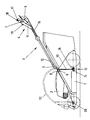
- the lawn mower in particular pushed or self-propelled, shown in the accompanying drawing, is essentially constituted by a casing 1 housing one or more cutting blades and on which is mounted a motor 2 driving the blade (s), by a handlebar 3 and by a control device 4, the handlebar 3 being constituted by a lower element 5 fixed on the casing 1 of the mower and by an upper element 6 fixed in an adjustable manner in position on the lower element 5 and the control device 4 comprising elements 7 for individual actuation of several functions by means of linear transmissions.
- the lower handlebar element 5 is provided with a hooking hook 8 on a part 9 of the casing 1 of the mower and with a detachable securing means 10 on said casing 1.
- the elements 7 for individual actuation of several functions are grouped together on a single control unit 11 which is removably fixed to the upper element 6 of the handlebar 3 and the corresponding linear transmissions are mounted in a flexible sheath 12 which is connected, on the one hand, to the casing 1 of the mower independently of the handlebars 3 and, on the other hand, to the control unit 11.
- the means 10 for detachably securing the lower handlebar element 5 is advantageously constituted in the form of a flat tongue 13 provided at the lower end of said element 5 and penetrating into a housing 14 of corresponding shape of the casing 1 and by a pin 15 passing through corresponding holes in the tongue 13 and the walls of the housing 14, said pin 15 itself being provided with a safety pin (not shown).
- the mounting of the handlebar 3 on the casing 1 is perfectly rigid and the disassembly of the said handlebar 3 is made particularly easy, since it is sufficient to dismantle the pin 15 to remove the lower part 5 of casing 1 by vertical extraction.
- the control unit 11 is fixed to the upper handlebar element 6, on the one hand, by fitting and cooperation in the form of a housing of its lower part on a plate 16 secured to said element 6 and, on the other hand, by locking the nested position by means of a pin 17 penetrating, on the side opposite to the nesting, in the crosspiece 18 of the upper element handlebar 6 and maneuverable, against the action of a spring, by a button 19.
- the establishment of the housing 11 can be achieved simply by fitting the housing of its lower part on the plate 16 and then by inserting the axis 17 in the corresponding hole of the crosspiece 18 of the element 6 by maneuvering by means of the button 19.
- the casing 1 is provided near its front end with another housing 20 intended to cooperate with the axis 17 of the housing 11, which is further provided with an elastic element d 'snap (not shown) cooperating with the housing or an appendage thereof.
- This embodiment allows the folding of the housing 11 secured to the flexible sheath 12 above the motor 2 and its attachment to the casing 1 for transport and packaging.
- the invention it is possible to produce a push or self-propelled lawn mower allowing complete and rapid disassembly of the handlebars, in particular for transport and packaging and the transmissions of which are safely and aesthetically grouped in a single sheath integral with a single control unit.
Landscapes
- Life Sciences & Earth Sciences (AREA)
- Environmental Sciences (AREA)
- Harvester Elements (AREA)
- Agricultural Chemicals And Associated Chemicals (AREA)
Priority Applications (1)
| Application Number | Priority Date | Filing Date | Title |
|---|---|---|---|
| AT89440017T ATE75902T1 (de) | 1988-02-25 | 1989-02-23 | Rasenmaeher, insbesondere von hand gefuehrt oder selbstfahrend. |
Applications Claiming Priority (2)
| Application Number | Priority Date | Filing Date | Title |
|---|---|---|---|
| FR8802575A FR2627659B1 (es) | 1988-02-25 | 1988-02-25 | |
| FR8802575 | 1988-02-25 |
Publications (2)
| Publication Number | Publication Date |
|---|---|
| EP0330596A1 EP0330596A1 (fr) | 1989-08-30 |
| EP0330596B1 true EP0330596B1 (fr) | 1992-05-13 |
Family
ID=9363794
Family Applications (1)
| Application Number | Title | Priority Date | Filing Date |
|---|---|---|---|
| EP89440017A Expired - Lifetime EP0330596B1 (fr) | 1988-02-25 | 1989-02-23 | Tondeuse à gazon, en particulier poussée ou autotractée |
Country Status (6)
| Country | Link |
|---|---|
| EP (1) | EP0330596B1 (es) |
| AT (1) | ATE75902T1 (es) |
| DE (2) | DE68901475D1 (es) |
| ES (1) | ES2012019T3 (es) |
| FR (1) | FR2627659B1 (es) |
| PT (1) | PT89821B (es) |
Families Citing this family (1)
| Publication number | Priority date | Publication date | Assignee | Title |
|---|---|---|---|---|
| EP1106046A1 (en) * | 1999-12-03 | 2001-06-13 | The Toro Company | Ground speed control system for lawn mower |
Family Cites Families (3)
| Publication number | Priority date | Publication date | Assignee | Title |
|---|---|---|---|---|
| US2757013A (en) * | 1954-01-19 | 1956-07-31 | Outboard Marine & Mfg Co | Handle mounting for lawn mowers and other implements |
| US3423103A (en) * | 1965-08-07 | 1969-01-21 | Gen Electric Canada | Coaxial handle arrangement |
| FR2551942B1 (fr) * | 1983-09-21 | 1985-11-08 | Wolf Outils | Dispositif de commande et panier de ramassage d'herbe pour tondeuse a gazon |
-
1988
- 1988-02-25 FR FR8802575A patent/FR2627659B1/fr not_active Expired - Fee Related
-
1989
- 1989-02-23 PT PT89821A patent/PT89821B/pt not_active IP Right Cessation
- 1989-02-23 ES ES198989440017T patent/ES2012019T3/es not_active Expired - Lifetime
- 1989-02-23 DE DE8989440017T patent/DE68901475D1/de not_active Expired - Fee Related
- 1989-02-23 EP EP89440017A patent/EP0330596B1/fr not_active Expired - Lifetime
- 1989-02-23 AT AT89440017T patent/ATE75902T1/de not_active IP Right Cessation
- 1989-02-23 DE DE198989440017T patent/DE330596T1/de active Pending
Also Published As
| Publication number | Publication date |
|---|---|
| DE68901475D1 (de) | 1992-06-17 |
| FR2627659B1 (es) | 1991-09-06 |
| ES2012019T3 (es) | 1993-01-01 |
| PT89821A (pt) | 1989-10-04 |
| ATE75902T1 (de) | 1992-05-15 |
| EP0330596A1 (fr) | 1989-08-30 |
| DE330596T1 (de) | 1990-03-22 |
| ES2012019A4 (es) | 1990-03-01 |
| PT89821B (pt) | 1994-04-29 |
| FR2627659A1 (es) | 1989-09-01 |
Similar Documents
| Publication | Publication Date | Title |
|---|---|---|
| FR2565772A1 (fr) | Appareil pour emonder les vignes | |
| EP2380424B1 (fr) | Tête de coupe rotative utilisant des éléments de coupe flexibles filiformes, et appareils de coupe munis d'une telle tête de coupe. | |
| EP0876756B1 (fr) | Ecarteur pour relevage de vigne | |
| FR2628488A1 (fr) | Attache rapide du type a baionnette perfectionnee | |
| FR2566989A1 (fr) | Outil de culture avec sa poignee et procede de culture. | |
| EP0809928A1 (fr) | Machine de coupe | |
| EP1125487B1 (fr) | Machine polyvalente de culture interpieds pour plantations d'arbres ou arbustes telles que vignes ou vergers | |
| EP0622008B1 (fr) | Rateau mécanique permettant de défricher, tondre, araser, ratisser toutes sortes d'herbes et végétaux divers | |
| BE1004554A3 (fr) | Appareil pour le moissonnage du mais ou d'autres cereales. | |
| EP2111098B1 (fr) | Dispositif de deroulage d'un fil support souple pour plants grimpants | |
| EP0330596A1 (fr) | Tondeuse à gazon, en particulier poussée ou autotractée | |
| FR2555860A1 (fr) | Appareil de travail du sol entre plants, a effacement automatique, adaptable sur tout vehicule ou autre agricole ou similaire | |
| EP0456592B1 (fr) | Dispositif de ramassage pour tondeuse à gazon muni d'un fond amovible permettant de déposer directement l'herbe coupée | |
| FR2651089A1 (fr) | Perfectionnements apportes aux tetes de debrouissailleuses portatives. | |
| FR2842861A1 (fr) | Dispositif de forage destine a etre utilise pour la culture de la vigne ou autres arbustes plantes en rangs serres | |
| FR2767447A1 (fr) | Outil de jardinage perfectionne | |
| FR2959096A1 (fr) | Dispositif d'outil pour le travail du sol | |
| FR2819456A1 (fr) | Dispositif de blocage en hauteur d'un appui-tete de siege, notamment de vehicule automobile | |
| FR2580142A1 (fr) | Dispositif de reglage en hauteur pour un appareil de traitement de gazons, notamment un scarificateur | |
| EP2166828B1 (fr) | Dispositif articule pour outil de jardin | |
| EP0553032A1 (fr) | Lame de labour et engin de labour comportant au moins une telle lame | |
| WO1998018307A1 (fr) | Sarcloir | |
| FR2967932A1 (fr) | Guide chaine adaptable a la coupe de differentes grosseurs de vegetaux et tronconneuse munie d'un tel guide chaine | |
| FR2666718A1 (fr) | Dispositif d'attelage multi-usages. | |
| FR2493674A1 (fr) | Outil rotatif de taillage de haies et analogues pouvant etre fixe sur un chargeur agricole porte par un tracteur |
Legal Events
| Date | Code | Title | Description |
|---|---|---|---|
| PUAI | Public reference made under article 153(3) epc to a published international application that has entered the european phase |
Free format text: ORIGINAL CODE: 0009012 |
|
| AK | Designated contracting states |
Kind code of ref document: A1 Designated state(s): AT BE CH DE ES GB IT LI NL SE |
|
| 17P | Request for examination filed |
Effective date: 19891107 |
|
| ITCL | It: translation for ep claims filed |
Representative=s name: ING. FISCHETTI WEBER |
|
| GBC | Gb: translation of claims filed (gb section 78(7)/1977) | ||
| TCAT | At: translation of patent claims filed | ||
| TCNL | Nl: translation of patent claims filed | ||
| DET | De: translation of patent claims | ||
| 17Q | First examination report despatched |
Effective date: 19901129 |
|
| GRAA | (expected) grant |
Free format text: ORIGINAL CODE: 0009210 |
|
| AK | Designated contracting states |
Kind code of ref document: B1 Designated state(s): AT BE CH DE ES GB IT LI NL SE |
|
| REF | Corresponds to: |
Ref document number: 75902 Country of ref document: AT Date of ref document: 19920515 Kind code of ref document: T |
|
| REF | Corresponds to: |
Ref document number: 68901475 Country of ref document: DE Date of ref document: 19920617 |
|
| ITF | It: translation for a ep patent filed | ||
| GBT | Gb: translation of ep patent filed (gb section 77(6)(a)/1977) | ||
| REG | Reference to a national code |
Ref country code: ES Ref legal event code: FG2A Ref document number: 2012019 Country of ref document: ES Kind code of ref document: T3 |
|
| PLBE | No opposition filed within time limit |
Free format text: ORIGINAL CODE: 0009261 |
|
| STAA | Information on the status of an ep patent application or granted ep patent |
Free format text: STATUS: NO OPPOSITION FILED WITHIN TIME LIMIT |
|
| 26N | No opposition filed | ||
| EAL | Se: european patent in force in sweden |
Ref document number: 89440017.5 |
|
| PGFP | Annual fee paid to national office [announced via postgrant information from national office to epo] |
Ref country code: GB Payment date: 19980220 Year of fee payment: 10 Ref country code: AT Payment date: 19980220 Year of fee payment: 10 |
|
| PGFP | Annual fee paid to national office [announced via postgrant information from national office to epo] |
Ref country code: SE Payment date: 19980224 Year of fee payment: 10 |
|
| PGFP | Annual fee paid to national office [announced via postgrant information from national office to epo] |
Ref country code: ES Payment date: 19980226 Year of fee payment: 10 |
|
| PGFP | Annual fee paid to national office [announced via postgrant information from national office to epo] |
Ref country code: NL Payment date: 19980228 Year of fee payment: 10 |
|
| PGFP | Annual fee paid to national office [announced via postgrant information from national office to epo] |
Ref country code: DE Payment date: 19980319 Year of fee payment: 10 |
|
| PGFP | Annual fee paid to national office [announced via postgrant information from national office to epo] |
Ref country code: BE Payment date: 19980402 Year of fee payment: 10 |
|
| PGFP | Annual fee paid to national office [announced via postgrant information from national office to epo] |
Ref country code: CH Payment date: 19980602 Year of fee payment: 10 |
|
| PG25 | Lapsed in a contracting state [announced via postgrant information from national office to epo] |
Ref country code: GB Free format text: LAPSE BECAUSE OF NON-PAYMENT OF DUE FEES Effective date: 19990223 Ref country code: AT Free format text: LAPSE BECAUSE OF NON-PAYMENT OF DUE FEES Effective date: 19990223 |
|
| PG25 | Lapsed in a contracting state [announced via postgrant information from national office to epo] |
Ref country code: SE Free format text: LAPSE BECAUSE OF NON-PAYMENT OF DUE FEES Effective date: 19990224 Ref country code: ES Free format text: LAPSE BECAUSE OF EXPIRATION OF PROTECTION Effective date: 19990224 |
|
| PG25 | Lapsed in a contracting state [announced via postgrant information from national office to epo] |
Ref country code: LI Free format text: LAPSE BECAUSE OF NON-PAYMENT OF DUE FEES Effective date: 19990228 Ref country code: CH Free format text: LAPSE BECAUSE OF NON-PAYMENT OF DUE FEES Effective date: 19990228 Ref country code: BE Free format text: LAPSE BECAUSE OF NON-PAYMENT OF DUE FEES Effective date: 19990228 |
|
| BERE | Be: lapsed |
Owner name: OUTILS WOLF S.A.R.L. Effective date: 19990228 |
|
| PG25 | Lapsed in a contracting state [announced via postgrant information from national office to epo] |
Ref country code: NL Free format text: LAPSE BECAUSE OF NON-PAYMENT OF DUE FEES Effective date: 19990901 |
|
| GBPC | Gb: european patent ceased through non-payment of renewal fee |
Effective date: 19990223 |
|
| REG | Reference to a national code |
Ref country code: CH Ref legal event code: PL |
|
| EUG | Se: european patent has lapsed |
Ref document number: 89440017.5 |
|
| PG25 | Lapsed in a contracting state [announced via postgrant information from national office to epo] |
Ref country code: DE Free format text: LAPSE BECAUSE OF NON-PAYMENT OF DUE FEES Effective date: 19991201 |
|
| REG | Reference to a national code |
Ref country code: ES Ref legal event code: FD2A Effective date: 20010601 |
|
| PG25 | Lapsed in a contracting state [announced via postgrant information from national office to epo] |
Ref country code: IT Free format text: LAPSE BECAUSE OF NON-PAYMENT OF DUE FEES Effective date: 20050223 |