EP0330571A1 - Mechanische Haltevorrichtung für optische Kabel mit freier Struktur - Google Patents
Mechanische Haltevorrichtung für optische Kabel mit freier Struktur Download PDFInfo
- Publication number
- EP0330571A1 EP0330571A1 EP89400502A EP89400502A EP0330571A1 EP 0330571 A1 EP0330571 A1 EP 0330571A1 EP 89400502 A EP89400502 A EP 89400502A EP 89400502 A EP89400502 A EP 89400502A EP 0330571 A1 EP0330571 A1 EP 0330571A1
- Authority
- EP
- European Patent Office
- Prior art keywords
- retention
- sheath
- cable
- block
- rod
- Prior art date
- Legal status (The legal status is an assumption and is not a legal conclusion. Google has not performed a legal analysis and makes no representation as to the accuracy of the status listed.)
- Granted
Links
Images
Classifications
-
- G—PHYSICS
- G02—OPTICS
- G02B—OPTICAL ELEMENTS, SYSTEMS OR APPARATUS
- G02B6/00—Light guides; Structural details of arrangements comprising light guides and other optical elements, e.g. couplings
- G02B6/44—Mechanical structures for providing tensile strength and external protection for fibres, e.g. optical transmission cables
- G02B6/4439—Auxiliary devices
-
- G—PHYSICS
- G02—OPTICS
- G02B—OPTICAL ELEMENTS, SYSTEMS OR APPARATUS
- G02B6/00—Light guides; Structural details of arrangements comprising light guides and other optical elements, e.g. couplings
- G02B6/44—Mechanical structures for providing tensile strength and external protection for fibres, e.g. optical transmission cables
- G02B6/4401—Optical cables
- G02B6/4407—Optical cables with internal fluted support member
-
- G—PHYSICS
- G02—OPTICS
- G02B—OPTICAL ELEMENTS, SYSTEMS OR APPARATUS
- G02B6/00—Light guides; Structural details of arrangements comprising light guides and other optical elements, e.g. couplings
- G02B6/44—Mechanical structures for providing tensile strength and external protection for fibres, e.g. optical transmission cables
- G02B6/4439—Auxiliary devices
- G02B6/4471—Terminating devices ; Cable clamps
Definitions
- the present invention relates to a mechanical retention device for fiber optic cable with free structure.
- the optical fiber cables must be mechanically connected to devices, the optical fibers themselves being connected to optical processing devices received in these devices.
- these cables are composed of a substantially cylindrical rod, possibly reinforced by a central carrier, provided with helical grooves at its periphery, each groove freely receiving an optical fiber, and an outer protective sheath, with possibly interposition of a shirt of braided locks.
- the assembly is said to be free structure since the optical fibers do not support the forces imparted to the mechanical elements of the cable, due to their free mounting in the grooves of the rod.
- the carrier is blocked in a central end piece and the cable is tightened on its protective sheath, by two separate means and connected to each other.
- the present invention aims to ensure good quality retention up to efforts of the order of 150 to 200 kgf, using means that are simple to implement.
- a device of this type is characterized in that it comprises a passage sheath for each optical fiber, freely traversed by a respective optical fiber and extending on one side under the protective sheath of the cable, said sleeves being molded in and passing through said retention block.
- the retention block owing to the fact that it is molded around the sheath and the rod, as well as around the carrier and the wicks if necessary, ensures an excellent mechanical transfer of the tensile forces between these constituents of the cable and any structure on which the block is attached.
- the freedom of the optical fibers vis-à-vis the rod is preserved in their crossing of the retention block, due to their free passage in sheaths molded in the block and extending under the cable sheath.
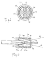
- the fiber optic cable 10 illustrated in section in FIG. 1 comprises, from the center towards the periphery: - A carrier 12, made in the form of a flexible rod, preferably resin reinforced with glass fibers, or any other synthetic fibers of high strength, or which may be made of metal.
- a rod 14 of substantially cylindrical shape, surrounding the carrier 12 and provided at its periphery with helical grooves 16, the pitch of the grooves being large, of the order of several times the diameter of the rod;
- the rod is surrounded by a first protective tape 20, then by braided reinforcing wicks 22, themselves surrounded by a second protective tape 24, the assembly being finally wrapped in a protective sheath 26.
- the reinforcing wicks are made of a material with high resistance, such as for example an aramid material.
- the cable 10 is shown in side view and equipped with a retention device 28 according to the present invention, shown in section in the figure.
- the device essentially consists of a retention block 30 of resin, molded directly around the carrier 12, of the grooved rod 14, of the reinforcing wicks 22 and of the protective sheath 26, on the bare areas of each of these elements, either successively a zone 12a of the wearer, a zone 14a of the rod, a length of wicks 22a and a zone 26a of the sheath.
- the molding of the block 30 is carried out inside a substantially cylindrical molding box 32, closed at one end by a bottom 34 pierced with an orifice allowing the passage of the sheath 26 and open at its other end.
- This box can have various shapes allowing it to be fixed to a fixed structure, such as threads, anti-rotation keys and bearing surfaces for seals. Due to its molding directly in contact with the various mechanical components of the cable, the block 30 ensures excellent transmission of the mechanical forces between the cable and the fixed structure.
- each optical fiber 18 is received with a slight play in a passage sheath 36, the sheaths being engaged at one end in the grooves corresponding to the optical fibers, that is to say under the protective sheath and under the braided reinforcing wicks , over a certain distance taking into account the flexibility of the sleeves and the pitch of the helix of the grooves, in any event a sufficient distance to avoid penetration of the resin into the grooves when filling the molding case with the liquid resin.
- the sleeves have a length such that they protrude at their other end beyond the block 30.
- the sheaths Due to their passage through the housing 32, the sheaths are therefore also molded in the resin block 30 but, the optical fibers passing through them freely, the free mounting of the fibers is also ensured at the crossing of the block.
- reinforcing wicks are embedded in the block along a winding path, as follows: from the stripped end of the sheath, they are first bent towards the bottom of the housing and held in place by an elastic ring 38 around the sheath, then bent again in the direction of the opening of the housing.
- the tongues can advantageously follow the same sinuous course as the reinforcing strands.
- a viscous liquid or an appropriate gel such as for example a silicone-based gel.
- One of the advantages of the invention also resides in the fact that the optical fibers, after their exit from the passage sheaths, are completely free vis-à-vis the cable retention elements.
- the retention element is sufficiently compact to largely release the fibers and allow free access to their end to prepare the connection.
Landscapes
- Physics & Mathematics (AREA)
- General Physics & Mathematics (AREA)
- Optics & Photonics (AREA)
- Light Guides In General And Applications Therefor (AREA)
Applications Claiming Priority (2)
| Application Number | Priority Date | Filing Date | Title |
|---|---|---|---|
| FR8802167A FR2627598B1 (fr) | 1988-02-23 | 1988-02-23 | Dispositif de retention mecanique pour cable a fibres optiques a structure libre |
| FR8802167 | 1988-02-23 |
Publications (2)
| Publication Number | Publication Date |
|---|---|
| EP0330571A1 true EP0330571A1 (de) | 1989-08-30 |
| EP0330571B1 EP0330571B1 (de) | 1993-06-16 |
Family
ID=9363525
Family Applications (1)
| Application Number | Title | Priority Date | Filing Date |
|---|---|---|---|
| EP89400502A Expired - Lifetime EP0330571B1 (de) | 1988-02-23 | 1989-02-23 | Mechanische Haltevorrichtung für optische Kabel mit freier Struktur |
Country Status (4)
| Country | Link |
|---|---|
| US (1) | US4928135A (de) |
| EP (1) | EP0330571B1 (de) |
| DE (1) | DE68907076T2 (de) |
| FR (1) | FR2627598B1 (de) |
Cited By (2)
| Publication number | Priority date | Publication date | Assignee | Title |
|---|---|---|---|---|
| EP0601497A1 (de) * | 1992-12-09 | 1994-06-15 | RXS Kabelgarnituren Gesellschaft mit beschränkter Haftung | Verfahren zur Herstellung eines Sperrstopfens zur Längsabdichtung von Kabeln, insbesondere Lichtwellenleiter-Kabeln |
| WO2008063054A2 (en) * | 2006-11-23 | 2008-05-29 | Optical Telecommunications Zederik Assembly B.V. | Holder for optical fibres or other conductors |
Families Citing this family (7)
| Publication number | Priority date | Publication date | Assignee | Title |
|---|---|---|---|---|
| US5013125A (en) * | 1989-10-02 | 1991-05-07 | Alcatel Na Cable Systems Inc. | Pulling eye assembly for connectorized optical fiber cables |
| DE9217326U1 (de) * | 1992-12-18 | 1994-04-28 | Bosch Gmbh Robert | Zugentlastungsvorrichtung für ein umspritztes elektrisches Kabel |
| US5425121A (en) * | 1994-02-02 | 1995-06-13 | Siecor Corporation | Cable assembly for use with opto-electronic equipment enclosures |
| US5416874A (en) * | 1994-07-01 | 1995-05-16 | Siecor Corporation | Optical receiver stub fitting |
| US5745633A (en) * | 1996-12-24 | 1998-04-28 | Siecor Corporation | Fiber optic cable assembly for securing a fiber optic cable within an input port of a splice closure |
| DE10046581A1 (de) * | 2000-09-20 | 2002-03-28 | Scc Special Comm Cables Gmbh | Kabelanordnung mit einem optischen Kabel und einem Abspannelement sowie Vorrichtung zur Herstellung einer Kabelanordnung |
| EP2674797B1 (de) * | 2012-06-13 | 2017-08-23 | TE Connectivity Nederland B.V. | Kabelhalterungsanordnung zur Befestigung von mindestens einem Kabel an einem Kabelträger sowie ein Verteiler mit einer derartigen Kabelhalterungsanordnung |
Citations (3)
| Publication number | Priority date | Publication date | Assignee | Title |
|---|---|---|---|---|
| DE3234484A1 (de) * | 1982-09-17 | 1984-03-22 | Licentia Patent-Verwaltungs-Gmbh, 6000 Frankfurt | Verfahren zum herstellen einer zugfesten verkappung am einziehende eines vieladrigen optischen kabels |
| US4460159A (en) * | 1981-10-09 | 1984-07-17 | Northern Telecom Limited | Optical cable and cable pulling attachment assemblies |
| DE3414363A1 (de) * | 1984-01-13 | 1985-10-17 | Roland 7000 Stuttgart Wolf | Zugfeste und feuchtigkeitsdichte verkappung von lichtwellenleiterkabeln, koaxialkabeln und starkstromkabeln |
Family Cites Families (5)
| Publication number | Priority date | Publication date | Assignee | Title |
|---|---|---|---|---|
| US4153332A (en) * | 1974-07-30 | 1979-05-08 | Industrie Pirelli Societa Per Azioni | Sheathed optical fiber element and cable |
| US4365865A (en) * | 1981-01-30 | 1982-12-28 | Sea-Log Corporation | Hybrid cable construction |
| EP0063506B1 (de) * | 1981-04-03 | 1984-08-08 | Lignes Telegraphiques Et Telephoniques L.T.T. | Schutzvorrichtung für freiliegende optische Fasern am Ende eines Kabelelements, Kabelelement mit einer derartigen Vorrichtung und Anwendung eines solchen Kabelelements |
| US4786137A (en) * | 1984-12-31 | 1988-11-22 | Ericsson, Inc. | Optical cable with filling compound and parallel fibers |
| FR2588387B1 (fr) * | 1985-10-04 | 1988-11-18 | Socapex | Element de connecteur hermaphrodite pour fibres optiques |
-
1988
- 1988-02-23 FR FR8802167A patent/FR2627598B1/fr not_active Expired - Lifetime
-
1989
- 1989-02-22 US US07/313,441 patent/US4928135A/en not_active Expired - Fee Related
- 1989-02-23 DE DE89400502T patent/DE68907076T2/de not_active Expired - Fee Related
- 1989-02-23 EP EP89400502A patent/EP0330571B1/de not_active Expired - Lifetime
Patent Citations (3)
| Publication number | Priority date | Publication date | Assignee | Title |
|---|---|---|---|---|
| US4460159A (en) * | 1981-10-09 | 1984-07-17 | Northern Telecom Limited | Optical cable and cable pulling attachment assemblies |
| DE3234484A1 (de) * | 1982-09-17 | 1984-03-22 | Licentia Patent-Verwaltungs-Gmbh, 6000 Frankfurt | Verfahren zum herstellen einer zugfesten verkappung am einziehende eines vieladrigen optischen kabels |
| DE3414363A1 (de) * | 1984-01-13 | 1985-10-17 | Roland 7000 Stuttgart Wolf | Zugfeste und feuchtigkeitsdichte verkappung von lichtwellenleiterkabeln, koaxialkabeln und starkstromkabeln |
Cited By (4)
| Publication number | Priority date | Publication date | Assignee | Title |
|---|---|---|---|---|
| EP0601497A1 (de) * | 1992-12-09 | 1994-06-15 | RXS Kabelgarnituren Gesellschaft mit beschränkter Haftung | Verfahren zur Herstellung eines Sperrstopfens zur Längsabdichtung von Kabeln, insbesondere Lichtwellenleiter-Kabeln |
| US5438163A (en) * | 1992-12-09 | 1995-08-01 | Rxs Schrumpftechnik Garnituren Gmbh | Blockstop for longitudinal sealing of a cable and a method of forming the blockstop |
| WO2008063054A2 (en) * | 2006-11-23 | 2008-05-29 | Optical Telecommunications Zederik Assembly B.V. | Holder for optical fibres or other conductors |
| WO2008063054A3 (en) * | 2006-11-23 | 2008-10-30 | Optical Telecomm Zederik Assem | Holder for optical fibres or other conductors |
Also Published As
| Publication number | Publication date |
|---|---|
| FR2627598A1 (fr) | 1989-08-25 |
| FR2627598B1 (fr) | 1992-04-10 |
| US4928135A (en) | 1990-05-22 |
| DE68907076T2 (de) | 1994-01-27 |
| EP0330571B1 (de) | 1993-06-16 |
| DE68907076D1 (de) | 1993-07-22 |
Similar Documents
| Publication | Publication Date | Title |
|---|---|---|
| EP0721246A1 (de) | Fixiervorrichtung, Massenschluss und Dichtung für ein optisches Kabel | |
| EP1174747B1 (de) | Halter für fadenförmige Körper mit kleinem Durchmesser und Bündel von fadenförmigen Körpern, welche durch diesen Halter miteinander verbunden sind | |
| EP0330571B1 (de) | Mechanische Haltevorrichtung für optische Kabel mit freier Struktur | |
| FR2757642A1 (fr) | Cable a fibres optiques a structure dissymetrique | |
| EP0063506A1 (de) | Schutzvorrichtung für freiliegende optische Fasern am Ende eines Kabelelements, Kabelelement mit einer derartigen Vorrichtung und Anwendung eines solchen Kabelelements | |
| FR2460491A1 (fr) | Perfectionnements aux cables optiques | |
| FR2601785A1 (fr) | Dispositif de reserve pour cable a fibre optique et le procede de mise en oeuvre | |
| FR2756935A1 (fr) | Cable a fibres optiques renforce, de structure unitube | |
| US11327231B2 (en) | Flexible splice protector assembly and method for preparing same | |
| FR2687801A1 (fr) | Cassette de fibres optiques. | |
| FR2370295A1 (fr) | Element optique destine a etre incorpore a un dispositif de transmission optique | |
| CA2456024C (fr) | Systeme de modification de la structure d'un harnais electrique | |
| FR2509872A1 (fr) | Cable de communication optique presentant un guide d'onde lumineuse et un recouvrement secondaire resistant a la traction | |
| FR2682775A1 (fr) | Dispositif d'amarrage de cables a fibres optiques. | |
| CA1253374A (fr) | Dispositif de raccordement d'un cable a fibres optiques a un boitier de jonction, et procede de fabrication de ce dispositif | |
| FR2590738A1 (fr) | Cable blinde equipe d'un collier de support ou de renfort | |
| FR2757643A1 (fr) | Cable a fibres optiques, flexible et de resistance elevee | |
| FR2723487A1 (fr) | Dispositif d'amarrage pour cables de telecommunications | |
| EP0263363B1 (de) | Zylindrischer Träger für ein optisches Kabel | |
| FR2633402A1 (fr) | Conducteur optique resistant a la traction | |
| EP0813695B1 (de) | Faseroptisches kabel mit äusserer hülle | |
| FR2502831A1 (fr) | Cable comportant une armature resistant a des contraintes elevees | |
| FR2564989A1 (fr) | Dispositif de rangement de cables a fibres optiques | |
| FR2641120A1 (en) | Self-supported overhead cable | |
| EP0165471A1 (de) | Zugfeste Bewehrung für Kabel und Kabel zur Anwendung unter Wasser mit einer ähnlichen Bewehrung versehen |
Legal Events
| Date | Code | Title | Description |
|---|---|---|---|
| PUAI | Public reference made under article 153(3) epc to a published international application that has entered the european phase |
Free format text: ORIGINAL CODE: 0009012 |
|
| AK | Designated contracting states |
Kind code of ref document: A1 Designated state(s): DE GB IT NL SE |
|
| 17P | Request for examination filed |
Effective date: 19900226 |
|
| 17Q | First examination report despatched |
Effective date: 19920128 |
|
| GRAA | (expected) grant |
Free format text: ORIGINAL CODE: 0009210 |
|
| AK | Designated contracting states |
Kind code of ref document: B1 Designated state(s): DE GB IT NL SE |
|
| ITF | It: translation for a ep patent filed |
Owner name: ING. ZINI MARANESI & C. S.R.L. |
|
| GBT | Gb: translation of ep patent filed (gb section 77(6)(a)/1977) |
Effective date: 19930623 |
|
| REF | Corresponds to: |
Ref document number: 68907076 Country of ref document: DE Date of ref document: 19930722 |
|
| PLBE | No opposition filed within time limit |
Free format text: ORIGINAL CODE: 0009261 |
|
| STAA | Information on the status of an ep patent application or granted ep patent |
Free format text: STATUS: NO OPPOSITION FILED WITHIN TIME LIMIT |
|
| 26N | No opposition filed | ||
| EAL | Se: european patent in force in sweden |
Ref document number: 89400502.4 |
|
| PGFP | Annual fee paid to national office [announced via postgrant information from national office to epo] |
Ref country code: NL Payment date: 19991213 Year of fee payment: 12 |
|
| PGFP | Annual fee paid to national office [announced via postgrant information from national office to epo] |
Ref country code: GB Payment date: 19991224 Year of fee payment: 12 |
|
| PGFP | Annual fee paid to national office [announced via postgrant information from national office to epo] |
Ref country code: DE Payment date: 19991229 Year of fee payment: 12 |
|
| PGFP | Annual fee paid to national office [announced via postgrant information from national office to epo] |
Ref country code: SE Payment date: 20000204 Year of fee payment: 12 |
|
| PG25 | Lapsed in a contracting state [announced via postgrant information from national office to epo] |
Ref country code: GB Free format text: LAPSE BECAUSE OF NON-PAYMENT OF DUE FEES Effective date: 20010223 |
|
| PG25 | Lapsed in a contracting state [announced via postgrant information from national office to epo] |
Ref country code: SE Free format text: LAPSE BECAUSE OF NON-PAYMENT OF DUE FEES Effective date: 20010224 |
|
| PG25 | Lapsed in a contracting state [announced via postgrant information from national office to epo] |
Ref country code: NL Free format text: LAPSE BECAUSE OF NON-PAYMENT OF DUE FEES Effective date: 20010901 |
|
| EUG | Se: european patent has lapsed |
Ref document number: 89400502.4 |
|
| GBPC | Gb: european patent ceased through non-payment of renewal fee |
Effective date: 20010223 |
|
| NLV4 | Nl: lapsed or anulled due to non-payment of the annual fee |
Effective date: 20010901 |
|
| PG25 | Lapsed in a contracting state [announced via postgrant information from national office to epo] |
Ref country code: DE Free format text: LAPSE BECAUSE OF NON-PAYMENT OF DUE FEES Effective date: 20011201 |
|
| PG25 | Lapsed in a contracting state [announced via postgrant information from national office to epo] |
Ref country code: IT Free format text: LAPSE BECAUSE OF NON-PAYMENT OF DUE FEES Effective date: 20050223 |