EP0330116A2 - Magnetischer Aufzeichnungsträger - Google Patents
Magnetischer Aufzeichnungsträger Download PDFInfo
- Publication number
- EP0330116A2 EP0330116A2 EP89102895A EP89102895A EP0330116A2 EP 0330116 A2 EP0330116 A2 EP 0330116A2 EP 89102895 A EP89102895 A EP 89102895A EP 89102895 A EP89102895 A EP 89102895A EP 0330116 A2 EP0330116 A2 EP 0330116A2
- Authority
- EP
- European Patent Office
- Prior art keywords
- magnetic
- thin film
- magnetic thin
- coercive force
- recording medium
- Prior art date
- Legal status (The legal status is an assumption and is not a legal conclusion. Google has not performed a legal analysis and makes no representation as to the accuracy of the status listed.)
- Granted
Links
Images


Classifications
-
- G—PHYSICS
- G11—INFORMATION STORAGE
- G11B—INFORMATION STORAGE BASED ON RELATIVE MOVEMENT BETWEEN RECORD CARRIER AND TRANSDUCER
- G11B5/00—Recording by magnetisation or demagnetisation of a record carrier; Reproducing by magnetic means; Record carriers therefor
- G11B5/62—Record carriers characterised by the selection of the material
- G11B5/64—Record carriers characterised by the selection of the material comprising only the magnetic material without bonding agent
- G11B5/65—Record carriers characterised by the selection of the material comprising only the magnetic material without bonding agent characterised by its composition
- G11B5/656—Record carriers characterised by the selection of the material comprising only the magnetic material without bonding agent characterised by its composition containing Co
-
- G—PHYSICS
- G11—INFORMATION STORAGE
- G11B—INFORMATION STORAGE BASED ON RELATIVE MOVEMENT BETWEEN RECORD CARRIER AND TRANSDUCER
- G11B5/00—Recording by magnetisation or demagnetisation of a record carrier; Reproducing by magnetic means; Record carriers therefor
- G11B5/62—Record carriers characterised by the selection of the material
- G11B5/64—Record carriers characterised by the selection of the material comprising only the magnetic material without bonding agent
- G11B5/65—Record carriers characterised by the selection of the material comprising only the magnetic material without bonding agent characterised by its composition
- G11B5/658—Record carriers characterised by the selection of the material comprising only the magnetic material without bonding agent characterised by its composition containing oxygen, e.g. molecular oxygen or magnetic oxide
-
- H—ELECTRICITY
- H01—ELECTRIC ELEMENTS
- H01F—MAGNETS; INDUCTANCES; TRANSFORMERS; SELECTION OF MATERIALS FOR THEIR MAGNETIC PROPERTIES
- H01F10/00—Thin magnetic films, e.g. of one-domain structure
- H01F10/08—Thin magnetic films, e.g. of one-domain structure characterised by magnetic layers
- H01F10/10—Thin magnetic films, e.g. of one-domain structure characterised by magnetic layers characterised by the composition
- H01F10/18—Thin magnetic films, e.g. of one-domain structure characterised by magnetic layers characterised by the composition being compounds
-
- Y—GENERAL TAGGING OF NEW TECHNOLOGICAL DEVELOPMENTS; GENERAL TAGGING OF CROSS-SECTIONAL TECHNOLOGIES SPANNING OVER SEVERAL SECTIONS OF THE IPC; TECHNICAL SUBJECTS COVERED BY FORMER USPC CROSS-REFERENCE ART COLLECTIONS [XRACs] AND DIGESTS
- Y10—TECHNICAL SUBJECTS COVERED BY FORMER USPC
- Y10S—TECHNICAL SUBJECTS COVERED BY FORMER USPC CROSS-REFERENCE ART COLLECTIONS [XRACs] AND DIGESTS
- Y10S428/00—Stock material or miscellaneous articles
- Y10S428/90—Magnetic feature
Definitions
- the present invention relates generally to magnetic thin films and, more particularly, is directed to a magnetic thin film for use as a perpendicular magnetic recording medium.
- Magnetic thin film As a magnetic thin film, or a magnetic thin film formed by the isotropy, i.e., surface magnetization used as a prior art magnetic thin film recording medium, there are known magnetic thin films utilizing alloys such as CoNi, CoP, CoPt and the like. These magnetic thin films made of these CoNi and CoP alloys have a hard magnetic characteristic utilizing a columnar structure.
- the films have a saturation magnetic flux density Bs of about 10 kG and a magnetic coercive force Hc equal to or less than about 1 k0e.
- the CoPt magnetic thin film is disclosed, for example, in Official Gazette of Japanese Laid-Open Patent Application No. 58-200513.
- this CoPt magnetic thin film has a thickness less than 300 ⁇ , the film has a high coercive force Hc of more than 1.5 k0e. However, with an increase of its film thickness, it demonstrates saturation magnetic flux density Bs of about 10kG, while it demonstrates the magnetic coercive force Hc of 700 Oe at most.
- the magnetic thin film which is made according to the perpendicular magnetization, use known magnetic thin films of alloys, such as CoCr, CoMo, CoV, CoRu and so on.
- alloys such as CoCr, CoMo, CoV, CoRu and so on.
- the film has a saturation magnetic flux density Bs that falls in a range of 4 kG to 6 kG and its perpendicular magnetic coervice force Hc ⁇ demonstrates a value of nearly about 1.5 k0e when a substrate temperature in the film-growing process such as a sputtering-process of this alloy film is about 150°C.
- the perpendicular coercive force Hc ⁇ becomes about 300 Oe. Then, a rectangular ratio (Mr/Ms) ⁇ in the perpendicular direction is about 0.2 and an anisotropic magnetic field Hk is about 4 to 6 k0e. In this case, because the saturation magnetic flux density Bs is relatively low and the perpendicular coervice force Hc ⁇ cannot be increased without increasing the substrate temperature during the film growing-process, it is impossible to use a relatively inexpensive polyethylene terephthalate (PET) substrate of low heat-resisting property as the substrate for the film.
- PET polyethylene terephthalate
- The, thus, made magnetic thin film is suitable for being applied to a perpendicular magnetic recording medium having high magnetic coercive force Hc ⁇ and high saturation
- The, thus, formed magnetic thin film is suitable for being applied to a perpendicular magnetic recording medium having high perpendicular anisotropic magnetic field which demonstrates high perpendicular magnetic coercive force Hc ⁇ and high saturation magnetic flux density Bs.
- The, thus, formed magnetic thin film is suitable for being applied to a perpendicular magnetic recording medium having high perpendicular magnetic coercive force Hc ⁇ or high saturation magnetic flux density Bs and which demonstrates high perpendicular anisotropic magnetic field.
- The, thus, made magnetic thin film demonstrates high magnetic coercive force Hc ⁇ and high saturation magnetic flux density Bs.
- a magnetic thin film was formed on a slide glass substrate by means of a magnetron-type sputtering apparatus.
- the sputtering conditions thereof were, by way of example, as follows: background vacuum degrees P BG : 4.0 x 10 ⁇ 6 Torr; substrate etching : High frequency of 300 W and for 5 minutes; substrate temperature : room temperature power for sputtering process : high frequency of 300 W; argon gas pressure : 8 x 10 ⁇ 3 Torr; argon flow amount : 60cc/minute; sputtering time : about 10 minutes; and thickness of magnetic thin film : 5000 ⁇ .
- a target was prepared in such a manner that three to six fan-shaped chips made of Pt having a thickness of 1 mm and having a predetermined extending angle from a center are formed on a base made of a CoBM-system alloy having a thickness of 3 mm and a diameter of 4 inches.
- a CoBMPt-system alloy target having a diameter of, for example, 4 inches and a thickness of 3 mm was prepared.
- a Co71Pt20B7Ti2 magnetic thin film was produced by utilizing a complex target and, according to the above-mentioned sputtering-method and under the above-mentioned conditions.
- the background vacuum degree P BG obtained by exhausting the sputtering chamber before the start of the sputtering-process was varied.
- oxygen concentrations in the resultant Co71Pt20B7Ti2 magnetic thin films under the respective background vacuum degrees P BG were measured, respectively.
- oxygen partial pressures equivalent to the respective background vacuum degrees P BG were measured in comparison with oxygen concentrations in the magnetic thin films. The measured results are indicated in the following TABLE 1.
- Magnetic thin films of various compositions were produced by using the complex target in which Pt chips were mounted on various kinds of alloy targets according to the above-mentioned sputtering-method and under the above-mentioned conditions in which the background vacuum degree P BG was selected to be 4 ⁇ Torr.
- Figs. 1A to 1C contains tables which, in the left-hand column, illustrate compositions (atomic percents) of the targets employed for making each of these magnetic thin films.
- compositions atomic percents
- the next columns have the compositions of the resultant thin films, the film thicknesses thereof and measured results of respective magnetic characteristics of perpendicular magnetic coercive force Hc ⁇ , surface magnetic coercive force Hc ⁇ , perpendicular anisotropic magnetic field Hk ⁇ , surface anistropic magnetic field Hk ⁇ , saturation magnetic flux density 4 ⁇ Ms, and a residual magnetization ratio Mr ⁇ /Mr ⁇ , which is between perpendicular residual magnetization Mr ⁇ and the surface residual magnetization Mr ⁇ .
- These magnetic characteristics demonstrate values shown in the diagrams of the surface magnetization curves of Fig. 2A and the perpendicular magnetization curves of Fig. 2B.
- the magnetic thin films which are obtained in the tables of Figs. 1A, 1B and 1C, contain oxygen of 4.2 to 10.7 atomic percents as will be clear from the TABLE 1 according to the embodiment 1.
- FIG. 3 illustrates a magnetic flux density B - magnetic field H curve characteristic.
- a solid line curve indicates a magnetization M - magnetic field H characteristic curve in the perpendicular direction
- a broken line curve indicates a magnetization M - magnetic field H characteristic curve in the surface direction.
- This target was formed of an alloy target of CoM-system having a diameter of 4 inches and a thickness of 3 mm. Three to six fan-shaped Pt chips having a thickness of 1 mm were located on the target to extend at predetermined angles from the center of the target.
- the target was formed of CoMPt-system alloy target having a diameter of, for example, 4 inches and a thickness of 3 mm.
- a Co76Pt22Ti2 magnetic thin film was produced by utilizing the complex target according to the above-mentioned sputtering-method and under the above-mentioned conditions.
- the background vacuum degree P BG obtained by exhausting the sputtering chamber prior to the start of the sputtering-process was varied.
- oxygen concentrations in the Co76Pt22Ti2 magnetic thin films which were obtained under the respective background vacuum degrees P BG were measured.
- the oxygen partial pressures equivalent to the respective background vacuum degrees P BG were measured in comparison with the oxygen concentrations in the magnetic thin films. The measured results were indicated in the following TABLE 2.
- Magnetic thin films having various kinds of compositions were produced by utilizing complex targets which comprise various alloy targets and Pt chips formed thereon according to the above-mentioned method and under the above-mentioned condition where the background vacuum degree P BG was selected to be 4 ⁇ Torr. Figs.
- 4A to 4F provide tables setting forth measured results of compositions (atomic percents) of the targets used for making these magnetic thin films, i.e., the alloy targets used therein, ratios (percents) with which the fan-shaped Pt chips occupy the total surface area of each of the targets, compositions of the resultant thin films, film thicknesses thereof and magnetic characteristics Hc ⁇ , Hc:, Hk ⁇ , Hk ⁇ , 4 Ms, Mr ⁇ /Mr ⁇ thereof.
- These magnetic characteristics are measured results of various values indicated on the diagram of the surface magnetization curve of Fig. 2A and the perpendicular magnetization curve of Fig.
- magnetic thin films contain 4.2 to 10.7 atomic percents of oxygen as will be clear from the TABLE 2 of the embodiment 4.
- FIG. 5 illustrates a magnetization M - magnetic field H characteristic curve in that case.
- a solid curve indicates a magnetization M - magnetic field H characteristic curve in the perpendicular direction and a broken curve indicates a magnetization M - magnetic field H characteristic curve in the surface direction.
- the experiments were carried out by utilizing a complex target which had three to six fan-shaped Pt chips, which have a thickness of 1 mm and extend on predetermined angles of 6°, 12° and 18° from the center of the target.
- the target is a Co 100-y B y alloy target having a diameter of 4 inches and a thickness of 3 mm where y represents atomic percent and satisfies an inequality of 0 ⁇ y ⁇ 25.
- the experiments were carried out by the use of a Co a Pt b B c alloy target having a diameter of 4 inches and a thickness of 3 mm, where a , b , and c represent atomic percents, respectively.
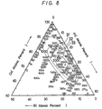
- Figs. 6 to 10 illustrate measured results thereof.
- the bottom assumes a composition ratio (atomic percent) of B
- the left slant leg assumes a composition ratio (atomic percent) of Co
- the right slant leg assumes a composition ratio (atomic percent) of Pt.
- Fig. 6 shows measured results of saturation magnetic flux density Bs (4 ⁇ Ms) (kG).
- thin curved lines 11, 12, 13 and 14 indicate isopleths in which the saturation magnetic flux density Bs is selected to be 7.5 kG, 10.0 kG, 12.5 kG and 15.0 kG, respectively.
- Fig. 7 illustrates measured results of ratio between perpendicular (normal to the film surface of magnetic thin film) residual magnetic flux density Mr ⁇ and the surface residual magnetic flux density Mr ⁇ .
- thin curved lines 21, 22 and 23 indicate isopleths in which Mr ⁇ /Mr ⁇ is selected to be 0.5, 1.0 and 1.5, respectively.
- Fig. 8 shows measured results of perpendicular magnetic coercive force Hc ⁇ (Oe).
- thin curved lines 31, 32 and 33 indicate isopleths in which the perpendicular magnetic coercive force Hc ⁇ is selected to be 1000 (Oe), 2000 (Oe) and 3000 (Oe), respectively.
- Fig. 9 shows measured results of the surface magnetic coercive force Hc ⁇ (Oe).
- thin lines 41 and 42 indicate isopleths in which the surface magnetic coercive force Hc ⁇ is selected to be 500 (Oe) and 1000 (Oe).
- Fig. 10 shows a relationship between the perpendicular anisotropic magnetic field Hk ⁇ (k0e) and each composition.
- a curve 51 indicates an isopleth in which the perpendicular anisotropic magnetic field Hk ⁇ is selected to be 15.0.
- a Co71Pt22B7 magnetic thin film was produced according to the method similar to that of the embodiment 7.
- the background vacuum degree P BG obained by exhausting the sputtering chamber prior to the start of the sputtering-process was varied.
- the oxygen concentrations contained in the resultant Co71Pt22B7 magnetic thin films under the respective vacuum degrees P BG were measured.
- oxygen partial pressures equivalent to the respective vacuum degrees P BG were measured in comparison with the oxygen concentrations contained in the respective magnetic thin films.
- TABLE 3 illustrates the measured values.
- FIG. 11 shows measured results of a relationship between the oxygen partial pressure (abscissa) in the sputtering-process and the perpendicular magnetic coercive force Hc (ordinate) with respect to the samples obtained under the condition that the background vacuum degree P BG was selected to be 1 ⁇ Torr and that the oxygen partial pressure in the sputtering-process was varied.
- an open square indicates measured result in which a Pt layer having a thickness of about 1500 ⁇ was deposited under the magnetic thin film as an under layer and an open circle shows measured result in which the under layer was not provided.
- a magnetic thin film was produced by utilizing a complex target in which six fan-shaped Pt chips having an extending angle of 6° were mounted on a Co92B8 alloy target.
- Fig. 12 shows measured results of the perpendicular magnetic coercive force Hc ⁇ and the perpendicular anisotropic magnetic field Hk with respect to samples obtained under the condition that the background vacuum degrees P BG was selected to be 1 ⁇ Torr and that the oxygen partial pressure P02 (abscissa) in the sputtering-process and the nitrogen partial pressure P N2 (abscissa) were changed.
- the background vacuum degrees P BG was selected to be 1 ⁇ Torr and that the oxygen partial pressure P02 (abscissa) in the sputtering-process and the nitrogen partial pressure P N2 (abscissa) were changed.
- an open circle indicates measured results of the perpendicular magnetic coercive force Hc ⁇ and a solid circle indicates measured results of the perpendicular anisotropic magnetic field Hk relative to the oxygen partial pressure P02, while an open square and solid square indicate measured results of the perpendicular magnetic coercive force Hc ⁇ and the perpendicular anisotropic magnetic field Hk, respectively, relative to the nitrogen partial pressure P N2 .
- FIG. 13 illustrates a magnetization M - magnetic field H characteristic curve in that case.
- a solid line curve is a magnetization M - magnetic field H characteristic curve in the perpendicular direction to the surface and a broken line curve is a magnetization M - magnetic field H characteristic curve in the surface direction. It should be understood from the above-mentioned curves that the resultant magnetic thin film is formed as an excellent perpendicular magnetization film having high magnetic coercive force Hc in the vertical or perpendicular direction.
- FIG. 14 illustrates a magnetic flux B - magnetic field H characteristic of the, thus, made magnetic thin film.
- a solid line curve indicates a perpendicular magnetization curve and a broken line curve indicates a surface magnetization curve, respectively.
- a magnetic thin film was produced in a similar manner to that of the embodiment 12.
- the film composition was selected as Co85Pt5B10.
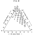
- Figs. 15 to 19 show measured results of a relationship between compositions and magnetic characteristics under the condition that the film compositions in the embodiment 13 were varied.
- the bottom assumes a composition ratio (atomic percent) of B
- the left slant leg assumes a composition ratio (atomic percent) of Co
- the right slant leg assumes a composition ratio (atomic percent) of Pt.
- Fig. 15 shows measured results of the perpendicular magnetic coercive force Hc ⁇ (Oe). Isopleths of 500 (Oe), 1000 (Oe), 1500 (Oe) and 2000 (Oe) are marked on the graph forming Fig. 15 as lines 131, 132 and 133, respectively.
- FIG. 16 shows measured results of the surface magnetic coercive force Hc ⁇ (Oe), and isopleths of 500 (Oe) and 800 (Oe) are marked on the graph forming Fig. 16 as lines 141 and 142, respectively.
- Fig. 17 shows measured results of the saturation magnetic flux density 4 Ms (kG), and isopleths of 5 (kG), 10 (kG), 13 (kG) and 15 (kG) are marked on the graph forming Fig. 17 as lines 111, 112, 113 and 114, respectively.
- Fig. 18 shows measured results of the perpendicular rectangular ration (Mr/Ms) ⁇ , and isopleths of 0.1 and 0.2 are marked on the graph forming Fig. 18 by lines 160 and 161, respectively.
- Fig. 19 shows measured results of the surface rectangular ratio (Mr/Ms) ⁇ , and an isopleth of 0.5 is marked on the graph which forms Fig. 19 by line 162.
- the above-mentioned magnetic characteristics are respectively measured by means of a so-called VSM (vibration sample-type magnetization characteristic measuring apparatus).
- VSM vibration sample-type magnetization characteristic measuring apparatus
- the compositions of the thin films are respectively measured by using an electron probe micro-analysis (EPMA) together with an IPS (inductively coupled plasma analysis) light emission analysis.
- EPMA electron probe micro-analysis
- IPS inductively coupled plasma analysis
- the oxygen concentrations in the thin films on the TABLE 1 are measured in comparison with standard samples of which oxygen dose amounts are clear by means of an SIMS (secondary ion mass spectrometer) method together with the EPMA method.
- SIMS secondary ion mass spectrometer
- slide glass substrate is used as the substrate in each of the above-mentioned embodiments, it is possible to use various substrates such as a polyamide resin substrate, a crystallized glass substrate, the PET substrate and the like.
- the magnetic thin film which can provide, without increasing the substrate temperature in the film growing process and even in the film thickness near or less than, for example, 5000 ⁇ , the high perpendicular magnetic coercive force Hc ⁇ , the high saturation magnetic flux density 4 ⁇ Ms and the high perpendicular anisotropic magnetic filed Hk ⁇ .
- the magnetic thin film is grown at room temperature, there are achieved large practical advantages, such that the inexpensive substrate, for example, the PET substrate or the like, can be utilized.
Landscapes
- Physics & Mathematics (AREA)
- Spectroscopy & Molecular Physics (AREA)
- Engineering & Computer Science (AREA)
- Power Engineering (AREA)
- Thin Magnetic Films (AREA)
- Magnetic Record Carriers (AREA)
Applications Claiming Priority (8)
| Application Number | Priority Date | Filing Date | Title |
|---|---|---|---|
| JP39264/88 | 1988-02-22 | ||
| JP63039264A JP2643227B2 (ja) | 1988-02-22 | 1988-02-22 | 磁性薄膜 |
| JP22626488A JP2625959B2 (ja) | 1988-09-09 | 1988-09-09 | 磁性薄膜 |
| JP226266/88 | 1988-09-09 | ||
| JP226265/88 | 1988-09-09 | ||
| JP22626588A JP2625960B2 (ja) | 1988-09-09 | 1988-09-09 | 磁性薄膜 |
| JP226264/88 | 1988-09-09 | ||
| JP63226266A JP2674131B2 (ja) | 1988-09-09 | 1988-09-09 | 磁性薄膜 |
Publications (3)
| Publication Number | Publication Date |
|---|---|
| EP0330116A2 true EP0330116A2 (de) | 1989-08-30 |
| EP0330116A3 EP0330116A3 (en) | 1990-12-27 |
| EP0330116B1 EP0330116B1 (de) | 1995-12-13 |
Family
ID=27460730
Family Applications (1)
| Application Number | Title | Priority Date | Filing Date |
|---|---|---|---|
| EP89102895A Expired - Lifetime EP0330116B1 (de) | 1988-02-22 | 1989-02-20 | Magnetischer Aufzeichnungsträger |
Country Status (3)
| Country | Link |
|---|---|
| EP (1) | EP0330116B1 (de) |
| KR (1) | KR970007795B1 (de) |
| DE (1) | DE68925045T2 (de) |
Cited By (6)
| Publication number | Priority date | Publication date | Assignee | Title |
|---|---|---|---|---|
| EP0413423A3 (en) * | 1989-08-16 | 1991-10-30 | International Business Machines Corporation | Thin film metal alloy magnetic recording disk |
| EP0415431A3 (en) * | 1989-08-30 | 1992-03-04 | Sony Corporation | Magnetic recording medium |
| EP0669610A1 (de) * | 1994-01-28 | 1995-08-30 | Komag, Inc. | Magnetische Legierung mit verbesserter Korrosionsbeständigkeit sowie verbesserten magnetischen Kennwerten |
| US6251532B1 (en) * | 1994-11-11 | 2001-06-26 | Hitachi, Ltd. | Magnetic recording medium and magnetic storage device using the same |
| US7105240B2 (en) * | 2003-06-03 | 2006-09-12 | Seagate Technology Llc | Perpendicular media with improved corrosion performance |
| US20110129692A1 (en) * | 2004-08-02 | 2011-06-02 | Seagate Technologies Llc | Magnetic alloy materials with hcp stabilized microstructure, magnetic recording media comprising same, and fabrication method therefor |
Family Cites Families (5)
| Publication number | Priority date | Publication date | Assignee | Title |
|---|---|---|---|---|
| JPS57149706A (en) * | 1981-03-12 | 1982-09-16 | Tdk Corp | Magnetic recording medium |
| JPS57183004A (en) * | 1981-05-07 | 1982-11-11 | Fuji Photo Film Co Ltd | Magnetically recording medium |
| JPS6115941A (ja) * | 1984-06-30 | 1986-01-24 | Res Dev Corp Of Japan | 酸素を含む強磁性非晶質合金およびその製造法 |
| FR2583211B1 (fr) * | 1985-06-05 | 1988-02-19 | Centre Nat Rech Scient | Nouvelles couches minces magnetiques a anisotropie uniaxiale, leur preparation et leur application |
| US4652499A (en) * | 1986-04-29 | 1987-03-24 | International Business Machines | Magnetic recording medium with a chromium alloy underlayer and a cobalt-based magnetic layer |
-
1989
- 1989-02-20 DE DE68925045T patent/DE68925045T2/de not_active Expired - Fee Related
- 1989-02-20 KR KR1019890001965A patent/KR970007795B1/ko not_active Expired - Fee Related
- 1989-02-20 EP EP89102895A patent/EP0330116B1/de not_active Expired - Lifetime
Cited By (8)
| Publication number | Priority date | Publication date | Assignee | Title |
|---|---|---|---|---|
| EP0413423A3 (en) * | 1989-08-16 | 1991-10-30 | International Business Machines Corporation | Thin film metal alloy magnetic recording disk |
| EP0415431A3 (en) * | 1989-08-30 | 1992-03-04 | Sony Corporation | Magnetic recording medium |
| EP0669610A1 (de) * | 1994-01-28 | 1995-08-30 | Komag, Inc. | Magnetische Legierung mit verbesserter Korrosionsbeständigkeit sowie verbesserten magnetischen Kennwerten |
| US5631094A (en) * | 1994-01-28 | 1997-05-20 | Komag, Incorporated | Magnetic alloy for improved corrosion resistance and magnetic performance |
| US5908514A (en) * | 1994-01-28 | 1999-06-01 | Ranjan; Rajiv Yadav | Magnetic alloy for improved corrosion resistance and magnetic performance |
| US6251532B1 (en) * | 1994-11-11 | 2001-06-26 | Hitachi, Ltd. | Magnetic recording medium and magnetic storage device using the same |
| US7105240B2 (en) * | 2003-06-03 | 2006-09-12 | Seagate Technology Llc | Perpendicular media with improved corrosion performance |
| US20110129692A1 (en) * | 2004-08-02 | 2011-06-02 | Seagate Technologies Llc | Magnetic alloy materials with hcp stabilized microstructure, magnetic recording media comprising same, and fabrication method therefor |
Also Published As
| Publication number | Publication date |
|---|---|
| HK1007625A1 (en) | 1999-04-16 |
| DE68925045T2 (de) | 1996-08-22 |
| EP0330116B1 (de) | 1995-12-13 |
| KR890013607A (ko) | 1989-09-25 |
| EP0330116A3 (en) | 1990-12-27 |
| KR970007795B1 (ko) | 1997-05-16 |
| DE68925045D1 (de) | 1996-01-25 |
Similar Documents
| Publication | Publication Date | Title |
|---|---|---|
| US6309765B1 (en) | Magnetic recording medium and process for its production | |
| US5587026A (en) | Ferromagnetic film | |
| US20010036564A1 (en) | Magnetic recording medium and manufacturing method thereof | |
| US20040084298A1 (en) | Fabrication of nanocomposite thin films for high density magnetic recording media | |
| US5516547A (en) | Method for fabricating magnetic recording medium | |
| EP0330116A2 (de) | Magnetischer Aufzeichnungsträger | |
| US5529814A (en) | Method of producing exchange coupled magnetic thin films with post-deposition annealing | |
| US4362767A (en) | Magnetic thin film and method of making it | |
| JP2674132B2 (ja) | 磁気記録媒体 | |
| EP0660341A1 (de) | Dünnschicht mit künstlichen Gitter und Element mit magnetoresistiven Effekt daraus | |
| EP0576376B1 (de) | Kobalt-Platin magnetischer Film und Herstellungsverfahren | |
| JPS6240363A (ja) | 雰囲気変動に対する薄膜磁気特性の安定度の高いタ−ゲツト材 | |
| US4840845A (en) | Magnetic recording medium having perpendicular magnetic anisotropy | |
| HK1007625B (en) | Magnetic recording medium | |
| US5626973A (en) | Magneto-optical layer and magneto-optical recording medium | |
| EP0505783A1 (de) | Magnetisches Aufnahmemedium | |
| Nakagawa et al. | Preparation of soft magnetic and thermally stable Fe–Co–Ta: N/Ti multilayered films by sputter deposition | |
| EP0262224B1 (de) | Magnetisches aufnahmemedium | |
| JP2674131B2 (ja) | 磁性薄膜 | |
| JPH03263306A (ja) | 磁性体膜および磁気ヘッド | |
| US6303240B1 (en) | Soft magnetic thin film | |
| JPS62208412A (ja) | 磁気記録媒体およびその製造方法 | |
| Nakagawa et al. | Improvement of soft magnetism of Fe90Co10 sputtered films by addition of N and Ta | |
| JP3230212B2 (ja) | 磁気記録媒体 | |
| JPH03265105A (ja) | 軟磁性積層膜 |
Legal Events
| Date | Code | Title | Description |
|---|---|---|---|
| PUAI | Public reference made under article 153(3) epc to a published international application that has entered the european phase |
Free format text: ORIGINAL CODE: 0009012 |
|
| AK | Designated contracting states |
Kind code of ref document: A2 Designated state(s): DE FR GB NL |
|
| PUAL | Search report despatched |
Free format text: ORIGINAL CODE: 0009013 |
|
| AK | Designated contracting states |
Kind code of ref document: A3 Designated state(s): DE FR GB NL |
|
| 17P | Request for examination filed |
Effective date: 19901220 |
|
| 17Q | First examination report despatched |
Effective date: 19920923 |
|
| GRAA | (expected) grant |
Free format text: ORIGINAL CODE: 0009210 |
|
| AK | Designated contracting states |
Kind code of ref document: B1 Designated state(s): DE FR GB NL |
|
| REF | Corresponds to: |
Ref document number: 68925045 Country of ref document: DE Date of ref document: 19960125 |
|
| ET | Fr: translation filed | ||
| PLBE | No opposition filed within time limit |
Free format text: ORIGINAL CODE: 0009261 |
|
| STAA | Information on the status of an ep patent application or granted ep patent |
Free format text: STATUS: NO OPPOSITION FILED WITHIN TIME LIMIT |
|
| 26N | No opposition filed | ||
| REG | Reference to a national code |
Ref country code: GB Ref legal event code: IF02 |
|
| PGFP | Annual fee paid to national office [announced via postgrant information from national office to epo] |
Ref country code: FR Payment date: 20020212 Year of fee payment: 14 |
|
| PGFP | Annual fee paid to national office [announced via postgrant information from national office to epo] |
Ref country code: GB Payment date: 20020220 Year of fee payment: 14 |
|
| PGFP | Annual fee paid to national office [announced via postgrant information from national office to epo] |
Ref country code: NL Payment date: 20020228 Year of fee payment: 14 |
|
| PGFP | Annual fee paid to national office [announced via postgrant information from national office to epo] |
Ref country code: DE Payment date: 20020306 Year of fee payment: 14 |
|
| PG25 | Lapsed in a contracting state [announced via postgrant information from national office to epo] |
Ref country code: GB Free format text: LAPSE BECAUSE OF NON-PAYMENT OF DUE FEES Effective date: 20030220 |
|
| PG25 | Lapsed in a contracting state [announced via postgrant information from national office to epo] |
Ref country code: NL Free format text: LAPSE BECAUSE OF NON-PAYMENT OF DUE FEES Effective date: 20030901 |
|
| PG25 | Lapsed in a contracting state [announced via postgrant information from national office to epo] |
Ref country code: DE Free format text: LAPSE BECAUSE OF NON-PAYMENT OF DUE FEES Effective date: 20030902 |
|
| GBPC | Gb: european patent ceased through non-payment of renewal fee | ||
| PG25 | Lapsed in a contracting state [announced via postgrant information from national office to epo] |
Ref country code: FR Free format text: LAPSE BECAUSE OF NON-PAYMENT OF DUE FEES Effective date: 20031031 |
|
| NLV4 | Nl: lapsed or anulled due to non-payment of the annual fee |
Effective date: 20030901 |
|
| REG | Reference to a national code |
Ref country code: FR Ref legal event code: ST |