EP0329797A1 - Vorrichtung zum Verzögern der Verriegelungs- oder Entriegelungsvorganges in einem Geradezugverschluss für Feuerwaffen - Google Patents
Vorrichtung zum Verzögern der Verriegelungs- oder Entriegelungsvorganges in einem Geradezugverschluss für Feuerwaffen Download PDFInfo
- Publication number
- EP0329797A1 EP0329797A1 EP87870207A EP87870207A EP0329797A1 EP 0329797 A1 EP0329797 A1 EP 0329797A1 EP 87870207 A EP87870207 A EP 87870207A EP 87870207 A EP87870207 A EP 87870207A EP 0329797 A1 EP0329797 A1 EP 0329797A1
- Authority
- EP
- European Patent Office
- Prior art keywords
- cylinder head
- breech
- cooperating
- barrel
- head
- Prior art date
- Legal status (The legal status is an assumption and is not a legal conclusion. Google has not performed a legal analysis and makes no representation as to the accuracy of the status listed.)
- Withdrawn
Links
Images


Classifications
-
- F—MECHANICAL ENGINEERING; LIGHTING; HEATING; WEAPONS; BLASTING
- F41—WEAPONS
- F41A—FUNCTIONAL FEATURES OR DETAILS COMMON TO BOTH SMALLARMS AND ORDNANCE, e.g. CANNONS; MOUNTINGS FOR SMALLARMS OR ORDNANCE
- F41A15/00—Cartridge extractors, i.e. devices for pulling cartridges or cartridge cases at least partially out of the cartridge chamber; Cartridge ejectors, i.e. devices for throwing the extracted cartridges or cartridge cases free of the gun
- F41A15/12—Cartridge extractors, i.e. devices for pulling cartridges or cartridge cases at least partially out of the cartridge chamber; Cartridge ejectors, i.e. devices for throwing the extracted cartridges or cartridge cases free of the gun for bolt-action guns
- F41A15/16—Cartridge extractors, i.e. devices for pulling cartridges or cartridge cases at least partially out of the cartridge chamber; Cartridge ejectors, i.e. devices for throwing the extracted cartridges or cartridge cases free of the gun for bolt-action guns the ejector being mounted on the breech housing or frame
-
- F—MECHANICAL ENGINEERING; LIGHTING; HEATING; WEAPONS; BLASTING
- F41—WEAPONS
- F41A—FUNCTIONAL FEATURES OR DETAILS COMMON TO BOTH SMALLARMS AND ORDNANCE, e.g. CANNONS; MOUNTINGS FOR SMALLARMS OR ORDNANCE
- F41A3/00—Breech mechanisms, e.g. locks
- F41A3/12—Bolt action, i.e. the main breech opening movement being parallel to the barrel axis
- F41A3/14—Rigid bolt locks, i.e. having locking elements rigidly mounted on the bolt or bolt handle and on the barrel or breech-housing respectively
- F41A3/16—Rigid bolt locks, i.e. having locking elements rigidly mounted on the bolt or bolt handle and on the barrel or breech-housing respectively the locking elements effecting a rotary movement about the barrel axis, e.g. rotating cylinder bolt locks
- F41A3/26—Rigid bolt locks, i.e. having locking elements rigidly mounted on the bolt or bolt handle and on the barrel or breech-housing respectively the locking elements effecting a rotary movement about the barrel axis, e.g. rotating cylinder bolt locks semi-automatically or automatically operated, e.g. having a slidable bolt-carrier and a rotatable bolt
-
- F—MECHANICAL ENGINEERING; LIGHTING; HEATING; WEAPONS; BLASTING
- F41—WEAPONS
- F41A—FUNCTIONAL FEATURES OR DETAILS COMMON TO BOTH SMALLARMS AND ORDNANCE, e.g. CANNONS; MOUNTINGS FOR SMALLARMS OR ORDNANCE
- F41A3/00—Breech mechanisms, e.g. locks
- F41A3/12—Bolt action, i.e. the main breech opening movement being parallel to the barrel axis
- F41A3/14—Rigid bolt locks, i.e. having locking elements rigidly mounted on the bolt or bolt handle and on the barrel or breech-housing respectively
- F41A3/16—Rigid bolt locks, i.e. having locking elements rigidly mounted on the bolt or bolt handle and on the barrel or breech-housing respectively the locking elements effecting a rotary movement about the barrel axis, e.g. rotating cylinder bolt locks
- F41A3/30—Interlocking means, e.g. locking lugs, screw threads
Definitions
- the present invention relates to a device for delaying the opening or latching of a movable breech of a firearm, this breech which is movable in an envelope or carcass being subjected to the action of an elastic means intended to bring it back in the vicinity of a chamber of a substantially cylindrical barrel and to the action of a pressure generated in said barrel by the explosion of a part of a projectile, said breech comprising a breech head and a breech body, the latter being able to undergo a relative movement relative to the breech head in a direction substantially parallel or coaxial with the axis of the barrel.
- the present invention also relates to a firearm provided with a device described in the preceding paragraph.
- This delay device is used to brake the recoil of the breech so as to use the above-mentioned pressure to the maximum for propelling the projectile.
- the device according to the invention makes it possible to delay or control the opening, the triggering and the retraction of the breech and also makes it possible to control the ejection of a part of a projectile, that is to say of the case or socket of this projectile.
- a first device of the type described in the first paragraph of this memo is known.
- This device known as an opening delay device by amplifying lever is characterized by the use of a lever for transmitting the above-mentioned pressure from the breech head to the breech body.
- This lever pivots around a shaft integral with the cylinder head and has a first end which acts on the cylinder head body and a second end which bears on the abovementioned carcass.
- This first known device has drawbacks, namely fouling and disassembly problems due to the fact that it comprises a large number of moving parts, some of which are located outside the cylinder head body.
- This other device is characterized by the use of a bolt head provided with rollers and a breech head, one end of which can slide in a breech body and the other end of which is beveled.
- the delay is obtained by the friction and the rolling of the rollers in grooves of the lock body and on the beveled end of the cylinder head.
- Such a device also presents difficulties of disassembly and problems of fouling and / or cleaning given the large number of moving parts that it comprises.
- the present invention relates to an opening or trigger delay device using a minimum number of simple and light mechanical means taking into account the high pressure generated in the barrel chamber.
- the present invention also relates to a device for delaying opening or triggering allowing high rates of fire of firearms. These high rates are obtained thanks to the use of a robust device composed of a minimum of parts making it possible to take up significant thermal and mechanical stresses.
- the device according to the invention of the type described in the first paragraph of this specification is essentially characterized in that the cylinder head head is provided with means cooperating with a lock body integral with the above-mentioned envelope and means cooperating with the body breech, the means cooperating with the bolt body being intended to rotate the breech head about an axis substantially parallel or coaxial with the axis of the barrel under the effect of pressure above, while the means cooperating with the breech body are intended to transform the rotational movement of the breech head into a relative movement of the breech body relative to the breech head in the aforementioned direction.
- the means cooperating with the lock body consist of at least one lug secured to the cylinder head, this lug having a sliding surface on at least part of a face a projection of the lock body when the bolt head is subjected to the aforementioned pressure.
- the means cooperating with the breech body are constituted by a groove which is formed in the breech head and in which a finger secured to the breech body is guided.
- the means cooperating with the breech body are constituted by at least one surface of the breech head, this surface being inclined relative to a plane perpendicular to the axis of the barrel and taking support on an inclined surface of the cylinder head body.
- the cylinder head is cylindrical and can slide in a bore in the cylinder head body.
- the breech head and the breech body each have a groove extending in a direction parallel to the axis of the barrel, these grooves being brought into a position where they face each other, when the breech head has rotated relative to the breech body so that, in this position, the grooves together form a channel delivering passage to a rod which is integral with the aforementioned envelope and can serve as an ejector of part of a projectile.
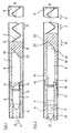
- Figures 1 and 2 show in cross section a first embodiment of a device according to the invention.
- This device makes it possible to delay the opening or the engagement of a movable breech 1 of a firearm such as a hunting rifle.
- This cylinder head is movable in an envelope or carcass 2 and is subjected to the action of an elastic means 3, such as a spring, intended to bring it in the vicinity of a chamber 4 of a substantially cylindrical barrel 5 and to the action of a pressure P generated in said barrel 5 by the explosion of a part of a projectile 6, such as an explosive substance contained in a case or a case 7 of a bullet.
- the spring 3 which bears on a wall 8 of the carcass 2 is advantageously partially bandaged, so that the cylinder head 1 is continuously subjected to a force in the direction of the arrow X tending to bring it back towards the chamber 4 .
- the breech 1 comprises a breech head 9 and a breech body 10, the latter being able to undergo a relative movement D relative to the breech head 9 in a direction substantially parallel or coaxial with the axis A-A of the barrel 5.
- the cylinder head 9 is provided with means 11 cooperating with a lock body 12 secured to the casing 2 and means 13 cooperating with the cylinder head body 10.
- the means 11 cooperating with the lock body 12 are intended to rotate (arrow Y) the breech head 9 around an axis parallel and, preferably, coaxial with the axis AA of the barrel under the effect of pressure (arrow P).
- the means 13 cooperating with the breech body 10 are intended to transform the rotational movement (arrow Y) of the breech head 9 into a relative movement (arrow D) of the breech body 10 relative to the breech head 9 in the direction coaxial with the axis AA of the barrel 5.
- the means 11 cooperating with the lock body 12 consist of two pins 14 integral with the cylinder head 9. These pins 14 have a surface 15 sliding on at least part of a face 16 of a projection 17 of the lock body 12 (see FIG. 3), when the cylinder head 9 is subjected to the above-mentioned pressure (P).
- the pins 14 are carried by a cylindrical part 18 of the cylinder head 9, these pins being advantageously diametrically opposite. Each of these pins 14 cooperates with a projection of a pair of diametrically opposite projections 17 and carried by a circular part 19 of the lock body 12.
- the surface 15 of the studs 14 and the face 16 of the projections 17 are advantageously helical and form, for example, an angle ⁇ of approximately 30 ° with a plane perpendicular to the axis A-A of the barrel 5.
- the cylinder head 9 is cylindrical and can slide in a bore 20 of the cylinder head body 10.
- This cylinder head 9 is provided, near its end 21 opposite to that provided with lugs 14, with means 13 cooperating with the body breech 10.
- These means 13 are constituted by a surface 22 of the breech head 9, this surface 22 being inclined with respect to a plane perpendicular to the axis AA of the barrel 5 and bearing on an inclined surface 23 of the breech body 10.
- the cylinder head 9 thus undergoes a rotation (arrow Y) around the axis AA, since the surface 15 of the pins 14 slides on the face 16 of the projections 17 of the lock body 12. This sliding slows the opening of the cylinder head since friction forces appear between the surface 15 and the face 16 and since the rotational movement (arrow Y) of the cylinder head 9 decreases the displacement component in the direction AA of this cylinder head 9.
- the breech head 9 is provided at its end 21 with cooperating means 13 with the cylinder head body 10.
- These means 13 are constituted by a surface 22 of the cylinder head 9 bearing on an inclined surface 23 of the cylinder head body 10.
- This compression of the elastic element 3 increases the friction forces appearing between the surface 22 of the cylinder head 9 and the surface 23 of the bore 20 of the cylinder head 10 and thus increases the frictional forces appearing between the surface 15 of the lugs 14 of the cylinder head 9 and the face 16 of the projections 17 of the lock body 12. These friction forces make it possible to delay the opening of the breech 1, that is to say that they make it possible to use the pressure P prevailing in the barrel 5 to the maximum for the propulsion of a projectile 24.
- the finger 26 is located in the vicinity of the end 28 of the groove 25 in the first step, while it moves from the end 28 towards the end 27 of the groove 25 during the second step.
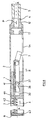
- Figures 6 to 8 show, in cross section, a second embodiment of a device according to the invention. This device is similar to that shown in Figures 1 and 2.
- This device comprises, like that shown in FIGS. 1 and 2, a cylinder head 9 provided with two studs 14, a cylinder head body 10, a lock body 12 carrying projections 17 and an elastic means 3 intended to bring the cylinder head 1 in the vicinity of chamber 4 of barrel 5.
- the cylinder head 9 differs from that shown in FIGS. 1 and 2 in that a striker 29 is shown therein and in that it is provided with other means 13 cooperating with the cylinder head body 10.
- the striker 29 consists, for example, of a thin rod 30 sliding in an orifice 31, of preferably symmetrical with respect to the axis AA of the barrel 5.
- This rod 30 is extended at one of its ends by a cylindrical counterweight 32.
- the rod 30 also carries a ring 33 which can slide in a chamber 34 formed in the breech head 9.
- This ring 33 is intended to serve as a stop for the striker 29, that is to say to prevent the striker 29 from coming out of the breech head 9, and to subject the striker to the action of a spring 35 which rests on an end face 36 of the chamber 34.
- the means 13 cooperating with the breech body 10 is constituted by a groove 37 formed in the breech head 9 and in which a finger 38 secured to the breech body 10 is guided.
- the breech body 10 and the breech head 9 each have a groove 39, 40 extending in a direction parallel to the axis A-A of the barrel 5 (see FIGS. 9 and 10). These grooves are brought into a position (FIG. 10) where they face each other when the cylinder head 9 has undergone a rotational movement (arrow Y) around the axis A-A. In this position ( Figures 7, 8 and 10) the grooves 39, 40 form a cylindrical channel 41 delivering passage to a rod 42 which is integral with the casing or carcass 2. This rod 42 is supported by a plate 43, on the end face 8 of the carcass 2 and is engaged in a hole 44 formed in one end 45 of the cylinder head body 10, this hole 44 communicating with the bore 20 of said body 10.
- This rod 42 can also serve as a guide rod for the elastic means or spring 3 since the latter is wound around this rod 42.
- This rod 42 thus allows better operation of the elastic means 3, since the latter can only undergo deformation in a direction parallel or coaxial with the axis AA.
- the groove 39 is formed in the cylinder head body 10 in the vicinity of the bore 20 in the extension of the hole 44.
- This pressure P acts, via the case 7, on the breech head 9.
- the latter undergoes a rotation (arrow Y) around the axis AA of the barrel, since the surface 15 of the lugs 14 of the breech head 9 slides on the face 16 of the projections 17 of the lock body 12.
- This rotation (arrow Y) is transformed into a relative movement D of the cylinder head body 10 relative to the cylinder head 9 in the direction of the axis AA.
- This relative displacement D is obtained by the displacement of the finger 38 integral with the cylinder head body 10 in the groove 37 formed in the cylinder head head 9.
- the rotation of the cylinder head head 9 forces the finger 38 to move from a first end 46 of the groove 37 towards a second end 47 of this groove.
- the rod 42 serves as a guide for the cylinder head 9 and the cylinder head body 10 during their movements, such as their recoil movements in the casing or carcass 2.
- the rod 42 may, in a preferred embodiment, s 'extend beyond the cylinder head 9 when the cylinder head 1 recedes into the carcass 2. In this case, this rod 42 can serve as an ejector from the case 7.
- the backward movement (arrow C) of the cylinder head 1 can open a window 54 formed in the carcass 2 to allow ejection, for example by means of the rod 42, of a case 7, while the movement of the breech 1 towards the chamber 4 of the barrel 5 (arrow B) can allow the introduction of a new case 7 provided with a bullet 24, for example from a magazine.
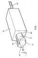
- FIG. 11 is a perspective view of the cylinder head 9 shown in FIGS. 6 to 10.
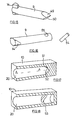
- FIGS. 12 and 13 are perspective views of means 11 provided on the cylinder head 9 which cooperate with the lock body 12.
- Figures 14, 15 and 16 are perspective views of means provided on the cylinder head 9, which cooperate with the cylinder head body 10 and Figures 17 and 18 are partial perspective views of the cylinder head body 10 corresponding to the heads of cylinder head 9 shown in FIGS. 15 and 16.
- the means provided on the cylinder head 9 which cooperate with the cylinder head body 10 consist of: - By at least one (for example three) helical surface 48 of the breech head 9 (FIG. 14), this surface bearing on a helical surface of the breech body 10; by two wedge-shaped surfaces 49, 50 (FIG. 15), these surfaces bearing on two surfaces 51, 52 of the cylinder head body 10, these surfaces 51, 52 being inclined, for example by an angle of 30 °, with respect to a plane perpendicular to the axis AA ( Figure 17), or - by a buttonhole or groove 53 which is provided in the cylinder head body 10 (FIG. 18) and in which is guided a finger 54 passing through a hole 55 in the cylinder head 9 ( Figure 16).
- the elastic means 3 can be a spring, a hydraulic or pneumatic system, an elastic material such as a foam material or a combination of these means.
Landscapes
- Engineering & Computer Science (AREA)
- General Engineering & Computer Science (AREA)
- Portable Nailing Machines And Staplers (AREA)
Priority Applications (1)
| Application Number | Priority Date | Filing Date | Title |
|---|---|---|---|
| EP87870207A EP0329797A1 (de) | 1987-12-29 | 1987-12-29 | Vorrichtung zum Verzögern der Verriegelungs- oder Entriegelungsvorganges in einem Geradezugverschluss für Feuerwaffen |
Applications Claiming Priority (1)
| Application Number | Priority Date | Filing Date | Title |
|---|---|---|---|
| EP87870207A EP0329797A1 (de) | 1987-12-29 | 1987-12-29 | Vorrichtung zum Verzögern der Verriegelungs- oder Entriegelungsvorganges in einem Geradezugverschluss für Feuerwaffen |
Publications (1)
| Publication Number | Publication Date |
|---|---|
| EP0329797A1 true EP0329797A1 (de) | 1989-08-30 |
Family
ID=8198510
Family Applications (1)
| Application Number | Title | Priority Date | Filing Date |
|---|---|---|---|
| EP87870207A Withdrawn EP0329797A1 (de) | 1987-12-29 | 1987-12-29 | Vorrichtung zum Verzögern der Verriegelungs- oder Entriegelungsvorganges in einem Geradezugverschluss für Feuerwaffen |
Country Status (1)
| Country | Link |
|---|---|
| EP (1) | EP0329797A1 (de) |
Cited By (1)
| Publication number | Priority date | Publication date | Assignee | Title |
|---|---|---|---|---|
| EP2017565A2 (de) * | 2007-07-20 | 2009-01-21 | BENELLI ARMI S.p.A. | Sperr- und Spannanordnung mit Schwenkverschluss und drehbarem Sperrkopf, insbesondere für träge Waffen mit kinetischer Rückstoßenergie |
Citations (7)
| Publication number | Priority date | Publication date | Assignee | Title |
|---|---|---|---|---|
| GB191500175A (en) * | 1915-01-05 | 1915-11-11 | Creedy Collins Sheppard | Improvements in Small Arms. |
| US1648833A (en) * | 1925-07-16 | 1927-11-08 | Gustavo vincon | |
| FR877884A (fr) * | 1941-02-25 | 1943-01-05 | Mauser Werke Ag | Mécanisme de culasse à mouvement rectiligne pour armes à feu automatiques |
| US2685754A (en) * | 1951-09-12 | 1954-08-10 | Remington Arms Co Inc | Breech-loading magazine firearm |
| US3407702A (en) * | 1967-06-08 | 1968-10-29 | Vyzk A Vyv Ustav Zd Vseob Stro | Automatic firearm with retarded blowback breech mechanism |
| US3938271A (en) * | 1973-04-05 | 1976-02-17 | Valmet Oy | Ejection port closure for firearms |
| CH577157A5 (en) * | 1974-01-14 | 1976-06-30 | Steyr Daimler Puch Ag | Automatic rifle breech bolt with rotating guide - has sliding block with releasing mechanism and stop actuated by gases (OE150575) |
-
1987
- 1987-12-29 EP EP87870207A patent/EP0329797A1/de not_active Withdrawn
Patent Citations (7)
| Publication number | Priority date | Publication date | Assignee | Title |
|---|---|---|---|---|
| GB191500175A (en) * | 1915-01-05 | 1915-11-11 | Creedy Collins Sheppard | Improvements in Small Arms. |
| US1648833A (en) * | 1925-07-16 | 1927-11-08 | Gustavo vincon | |
| FR877884A (fr) * | 1941-02-25 | 1943-01-05 | Mauser Werke Ag | Mécanisme de culasse à mouvement rectiligne pour armes à feu automatiques |
| US2685754A (en) * | 1951-09-12 | 1954-08-10 | Remington Arms Co Inc | Breech-loading magazine firearm |
| US3407702A (en) * | 1967-06-08 | 1968-10-29 | Vyzk A Vyv Ustav Zd Vseob Stro | Automatic firearm with retarded blowback breech mechanism |
| US3938271A (en) * | 1973-04-05 | 1976-02-17 | Valmet Oy | Ejection port closure for firearms |
| CH577157A5 (en) * | 1974-01-14 | 1976-06-30 | Steyr Daimler Puch Ag | Automatic rifle breech bolt with rotating guide - has sliding block with releasing mechanism and stop actuated by gases (OE150575) |
Cited By (2)
| Publication number | Priority date | Publication date | Assignee | Title |
|---|---|---|---|---|
| EP2017565A2 (de) * | 2007-07-20 | 2009-01-21 | BENELLI ARMI S.p.A. | Sperr- und Spannanordnung mit Schwenkverschluss und drehbarem Sperrkopf, insbesondere für träge Waffen mit kinetischer Rückstoßenergie |
| EP2017565A3 (de) * | 2007-07-20 | 2015-04-08 | BENELLI ARMI S.p.A. | Sperr- und Spannanordnung mit Schwenkverschluss und drehbarem Sperrkopf, insbesondere für träge Waffen mit kinetischer Rückstoßenergie |
Similar Documents
| Publication | Publication Date | Title |
|---|---|---|
| FR2680234A1 (fr) | Dispositif de commande multifonction d'arme a feu. | |
| EP0719998A2 (de) | Automatische oder halbautomatische Schusswaffe | |
| EP0779132B1 (de) | Vorrichtung zum Festsetzen von Befestigungselementen | |
| FR2620368A1 (fr) | Appareil de scellement a tir indirect a puissance de tir variable | |
| BE1005891A3 (fr) | Dispositif pour le freinage de la glissiere d'une arme a feu. | |
| FR2507762A1 (fr) | Arme a feu individuelle a tambour du type revolver a nombre de coups eleve et chargeur pour cette arme | |
| EP0329797A1 (de) | Vorrichtung zum Verzögern der Verriegelungs- oder Entriegelungsvorganges in einem Geradezugverschluss für Feuerwaffen | |
| FR2461918A1 (fr) | Mitrailleuse de type gatling a mecanisme de surete perfectionne | |
| FR2820673A1 (fr) | Porte-piston | |
| EP0578648B1 (de) | Schlagzündvorrichtung für mörsern oder ähnlichen geschützen | |
| EP3311102B1 (de) | Stiftloser granatenzünder und damit ausgerüstete granate | |
| BE1005385A3 (fr) | Dispositif permettant la reduction du poids de depart de la detente d'une carabine. | |
| EP0037791B1 (de) | Jagdgewehr | |
| EP0260204B1 (de) | Gasdruckbetätigtes automatisches Gewehr, z.B. Kipplaufgewehr | |
| EP3450898A1 (de) | Karabiner mit geradezugverschluss | |
| FR2622495A1 (fr) | Appareil de scellement a extracteur perfectionne | |
| EP1067353B1 (de) | Abfeuerungsvorrichtung für Geschütz durch den Schlag eines Zünders | |
| EP0381589B1 (de) | Sicherheitsvorrichtung für den Fall des Auftreffens auf eine durch eine Sprengstoffpatrone angetriebene Vorrichtung | |
| EP0399984A1 (de) | Hammersicherung für Feuerwaffen | |
| FR2599488A1 (fr) | Dispositif de declenchement d'armement et procede empechant un armement intempestif | |
| EP0361605A1 (de) | Auswerfer für Jagdgewehre | |
| FR2699662A1 (fr) | Système d'amorçage à détecteur d'impact tout azimut pour munition, en particulier pour sous-munition éjectée d'un obus cargo. | |
| WO1999060325A1 (fr) | Dispositif de percussion d'une carabine a culasse fixe | |
| FR3035491A1 (fr) | Mecanisme de fusil a canon basculant comportant un chien mis en tension lors de la fermeture du fusil | |
| BE527942A (de) |
Legal Events
| Date | Code | Title | Description |
|---|---|---|---|
| PUAI | Public reference made under article 153(3) epc to a published international application that has entered the european phase |
Free format text: ORIGINAL CODE: 0009012 |
|
| AK | Designated contracting states |
Kind code of ref document: A1 Designated state(s): AT BE CH DE ES FR GB IT LI LU NL SE |
|
| 17P | Request for examination filed |
Effective date: 19891023 |
|
| 17Q | First examination report despatched |
Effective date: 19901008 |
|
| STAA | Information on the status of an ep patent application or granted ep patent |
Free format text: STATUS: THE APPLICATION IS DEEMED TO BE WITHDRAWN |
|
| 18D | Application deemed to be withdrawn |
Effective date: 19940628 |